
Related Manuals for WAGO 750-637 Series


Summary of Contents for WAGO 750-637 Series
- Page 1 Fieldbus Independent I/O Modules Incremental Encoder Interfaces 750-637, (/xxx-xxx) Manual Version 1.3.2...
- Page 2 • General Copyright © 2006 by WAGO Kontakttechnik GmbH & Co. KG All rights reserved. WAGO Kontakttechnik GmbH & Co. KG Hansastraße 27 D-32423 Minden Phone: +49 (0) 571/8 87 – 0 Fax: +49 (0) 571/8 87 – 1 69 E-Mail: info@wago.com...
-
Page 3: Table Of Contents
Process Image ................24 2.1.4 750-637/000-002 [Inc.Enc./24V/32Bit/S.E.]........28 2.1.4.1 View....................28 2.1.4.2 Description..................28 2.1.4.3 Display Elements ................30 2.1.4.4 Schematic Diagram............... 30 2.1.4.5 Technical Data ................31 2.1.4.6 Functional Description..............33 2.1.4.7 Process Image ................34 WAGO-I/O-SYSTEM 750 I/O Modules... -
Page 4: Important Comments
WAGO Kontakttechnik GmbH & Co. KG declines all liability resulting from improper action and damage to WAGO products and third party products due to non-observance of the information contained in this manual. -
Page 5: Symbols
Routines or advice for efficient use of the device and software optimization. More information References on additional literature, manuals, data sheets and INTERNET pages 1.3 Number Notation Number Code Example Note Decimal normal notation Hexadecimal 0x64 C notation Binary '100' Within ', '0110.0100' Nibble separated with dots WAGO-I/O-SYSTEM 750 I/O Modules... -
Page 6: Safety Notes
Do not use any contact spray. The spray may impair the functioning of the contact area. The WAGO-I/O-SYSTEM 750 and its components are an open system. It must only be assembled in housings, cabinets or in electrical operation rooms. Access must only be given via a key or tool to authorized qualified personnel. -
Page 7: O Modules
Input differential differential single ended differential Sensor Operation DC 5 V DC 24 V DC 24 V DC 5 V Voltage Interpretation fourfold fourfold fourfold single Bit Width 32 Bit 32 Bit 32 Bit 32 Bit WAGO-I/O-SYSTEM 750 I/O Modules... -
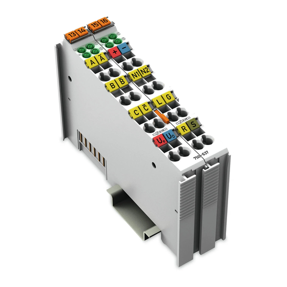
Page 8: 750-637 [Inc.enc./Rs422/32Bit/Diff.]
RS 422 connection. The data width of the encoder module is 32 bits. Either the current counter reading, the latch value, the set value or the current speed can be mapped into the process data. WAGO-I/O-SYSTEM 750 I/O Modules... - Page 9 The shield (screen) is directly connected to the carrier rail. The module 750-637 can be used with all couplers/controllers of the WAGO-I/O-SYSTEM 750 (except for the economy types 750-320, -323, -324 and -327). The version of both hardware and software that are valid for this module is specified in the manufacturing number, which is part of the lateral marking on the module.
-
Page 10: Display Elements
Output = 24 V 2.1.2.5 Schematic Diagram 24V/0V A B C _ _ _ A B C A,B,C N1/N2 N1/N2 Logic Latch Latch/Gate Gate/Ref Gate /Ref Latch Shield Ref/Shield Ve/V (screen) (screen) 750-637 Fig. 2.1.2-2: Schematic Diagram g063701e WAGO-I/O-SYSTEM 750 I/O Modules... -
Page 11: Technical Data
Output resistance 160 mΩ typ. Digital Inputs (Latch, Gate, Ref) Input voltage (0) DC –3 V ... +5 V (1) DC +15 V ... +30 V Input current Latch: 5 mA typ. Gate and Ref: 7 mA WAGO-I/O-SYSTEM 750 I/O Modules... - Page 12 II 3 GD EEx nA II T4 Conformity Marking More Information Detailed references to the approvals are listed in the document "Overview Approvals WAGO-I/O-SYSTEM 750", which You can find on the CD ROM ELECTRONICC Tools and Docs (Item-No.: 0888-0412/…) or in the Internet under: www.wago.com ->...
-
Page 13: Functional Description
Ground for the 24 V supply voltage, internally connected with U Output Function N1, N2 Cam output, 24 V, 0.5 A "1" - Counter value is within of the defined range "0" - Counter value is outside of the defined range WAGO-I/O-SYSTEM 750 I/O Modules... -
Page 14: Process Image
The setting is mirrored in status byte S1 in bit 0 and bit 1. MapPZD (Control Byte C1 / Status Byte S1, Bit 0 and 1) Bit 1 Bit 0 Coding of the Process data Counter value Latch value Velocity (Increments per milliseconds) Set value WAGO-I/O-SYSTEM 750 I/O Modules... - Page 15 Cam window 1st bit is set, if: bottom comparative value N1 ≤ counter reading ≤ top comparative value N1 Cam window 2nd bit is set, if: bottom comparative value N2 ≤ counter reading ≤ top comparative value N2 reserved WAGO-I/O-SYSTEM 750 I/O Modules...
- Page 16 OpMode 0=Capture Mode The counter is latched by a trigger signal 1=Preload Mode The counter is latched by a trigger signal. Subsequently, the counter is loaded with the set value. reserved WAGO-I/O-SYSTEM 750 I/O Modules...
- Page 17 - The controls must release EN_LATC (C1.0) or EN_LAT_EXT (C1.1) with a positive edge - A positive edge is created at input REF - Subsequently, the next positive edge at input C or input Latch leads to a Capture or Preload event reserved WAGO-I/O-SYSTEM 750 I/O Modules...
-
Page 18: 750-637/000-001 [Inc.enc./24V/32Bit/Diff.]
18 • 750-637/000-001 [Inc.Enc./24V/32Bit/Diff.] View 2.1.3 750-637/000-001 [Inc.Enc./24V/32Bit/Diff.] Incremental encoder interface 24 V / 32 bit / differential 2.1.3.1 View 13 14 15 16 Gate Latch Data contacts N1 N2 Gate Latch Shield (screen) 750-637/000-001 Fig. 2.1.3-1: View g063710e 2.1.3.2 Description The I/O module 750-637/000-001 represents an interface for any type of incremental encoder with an differential 24 V connection. - Page 19 The shield (screen) is directly connected to the carrier rail. The module 750-637/000-001 can be used with all couplers/controllers of the WAGO-I/O-SYSTEM 750 (except for the economy types 750-320, -323, -324 and -327). This description is valid for the XXXX0301... hardware and software version.
-
Page 20: Display Elements
20 • 750-637/000-001 [Inc.Enc./24V/32Bit/Diff.] Display Elements 2.1.3.3 Display Elements Designation Status Function -30 V < (U(A) - U(/A)) < -15 green 30 V > (U(A) - U(/A)) > 15 V or both inputs open -30 V < (U(C) - U(/C)) < -15 V 30 V >... -
Page 21: Technical Data
750-637/000-001 [Inc.Enc./24V/32Bit/Diff.] • 21 Technical Data 2.1.3.5 Technical Data Module specific Data Sensor connection A, /A, B, /B, C, /C (/A, /B, /C are inversed) Current consumption (internal) 110 mA Counter 32 bits binary Operation Mode Capture 32 bits Operation Mode Preload 32 bits Quadrature decoder 4-fold interpretation... - Page 22 Class I Div2 ABCD T4A Conformity Marking More Information Detailed references to the approvals are listed in the document "Overview Approvals WAGO-I/O-SYSTEM 750", which You can find on the CD ROM ELECTRONICC Tools and Docs (Item-No.: 0888-0412/…) or in the Internet under: www.wago.com ->...
-
Page 23: Functional Description
750-637/000-001 [Inc.Enc./24V/32Bit/Diff.] • 23 Functional Description 2.1.3.6 Functional Description Typically, incremental encoders supply two output signals of the encoder track, both 90° offset. These signals are designated A and B. To improve the common mode interference suppression, both signals are transmitted as differential signals. -
Page 24: Process Image
24 • 750-637/000-001 [Inc.Enc./24V/32Bit/Diff.] Process Image 2.1.3.7 Process Image Using the I/O module 750-637/000-001, a 6 byte input and output process image can be transferred to the fieldbus coupler / controller via two logical channels. The set values are stored in 4 output bytes (D0, D1, D2, D3) and the process data are stored in 4 input bytes (D0, D1, D2, D3). - Page 25 750-637/000-001 [Inc.Enc./24V/32Bit/Diff.] • 25 Process Image Status Byte S0 Bit 7 Bit 6 Bit 5 Bit 4 Bit 3 Bit 2 Bit 1 Bit 0 AckSet OVER- UNDER- CNT_ LAT_ LATC_ LoadExt FLOW FLOW SET_ EXT_ LATC_ Acknowledge bit for EN_LATC (C0.0). Latch Mode: This bit is set with a positive edge at input C.
- Page 26 26 • 750-637/000-001 [Inc.Enc./24V/32Bit/Diff.] Process Image Control Byte C0 Bit 7 Bit 6 Bit 5 Bit 4 Bit 3 Bit 2 Bit 1 Bit 0 OpMode SetLoad Reset Reset CNT_ Overflow Under- LAT_ LATC flow The encoder zero mark is released. LATC Capture Mode: With a positive edge at input C the counter reading is...
- Page 27 750-637/000-001 [Inc.Enc./24V/32Bit/Diff.] • 27 Process Image Control Byte C1 Bit 7 Bit 6 Bit 5 Bit 4 Bit 3 Bit 2 Bit 1 Bit 0 Enable MapPZD MapPZD Nocke2 Nocke1 Nocke2 Nocke1 MapPZD Coding of Process data (2 bits) DisNocke1 Disable cam output 1: 0 = cam output 1 enabled, 1 = cam output 1 disabled DisNocke2...
-
Page 28: 750-637/000-002 [Inc.enc./24V/32Bit/S.e.]
28 • 750-637/000-002 [Inc.Enc./24V/32Bit/S.E.] View 2.1.4 750-637/000-002 [Inc.Enc./24V/32Bit/S.E.] Incremental encoder interface 24 V / 32 bit / single ended 2.1.4.1 View 13 14 15 16 Gate Latch Data contacts N1 N2 Gate Latch Shield (screen) 750-637/000-002 Fig. 2.1.4-1: View g063720e 2.1.4.2 Description The I/O module 750-637/000-002 represents an interface for any type of... - Page 29 The shield (screen) is directly connected to the carrier rail. The module 750-637/000-002 can be used with all couplers/controllers of the WAGO-I/O-SYSTEM 750 (except for the economy types 750-320, -323, -324 and -327). This description is valid for the XXXX0301... hardware and software version.
-
Page 30: Display Elements
30 • 750-637/000-002 [Inc.Enc./24V/32Bit/S.E.] Display Elements 2.1.4.3 Display Elements Designation Status Function 0 V < U(A) < 5 V or input open green 30 V > U(A) > 15 V 0 V < U(C) < 5 V or input open green 30 V >... -
Page 31: Technical Data
750-637/000-002 [Inc.Enc./24V/32Bit/S.E.] • 31 Technical Data 2.1.4.5 Technical Data Module specific Data Sensor connection A, B, C, 0 V Current consumption (internal) 110 mA Counter 32 bits binary Operation Mode Capture 32 bits Operation Mode Preload 32 bits Quadrature decoder 4-fold report Zero impulse latch 32 bits... - Page 32 Class I Div2 ABCD T4A Conformity Marking More Information Detailed references to the approvals are listed in the document "Overview Approvals WAGO-I/O-SYSTEM 750", which You can find on the CD ROM ELECTRONICC Tools and Docs (Item-No.: 0888-0412/…) or in the Internet under: www.wago.com ->...
-
Page 33: Functional Description
750-637/000-002 [Inc.Enc./24V/32Bit/S.E.] • 33 Functional Description 2.1.4.6 Functional Description Typically, incremental encoders supply two output signals of the encoder track, both 90° offset. These signals are designated A and B. The difference of the input signals is evaluated in the incremental encoder I/O module. Usually, incremental encoders have an index track in addition to the two track signals. -
Page 34: Process Image
34 • 750-637/000-002 [Inc.Enc./24V/32Bit/S.E.] Process Image 2.1.4.7 Process Image Using the I/O module 750-637/000-002, a 6 byte input and output process image can be transferred to the fieldbus coupler / controller via two logical channels. The set values are stored in 4 output bytes (D0, D1, D2, D3) and the process data are stored in 4 input bytes (D0, D1, D2, D3). - Page 35 750-637/000-002 [Inc.Enc./24V/32Bit/S.E.] • 35 Process Image Status Byte S0 Bit 7 Bit 6 Bit 5 Bit 4 Bit 3 Bit 2 Bit 1 Bit 0 AckSet OVER- UNDER- CNT_ LAT_ LATC_ LoadExt FLOW FLOW SET_ EXT_ LATC_ Acknowledge bit for EN_LATC (C0.0). Latch Mode: This bit is set with a positive edge at input C.
- Page 36 36 • 750-637/000-002 [Inc.Enc./24V/32Bit/S.E.] Process Image Control Byte C0 Bit 7 Bit 6 Bit 5 Bit 4 Bit 3 Bit 2 Bit 1 Bit 0 OpMode SetLoad Reset Reset CNT_ Overflow Under- LAT_ LATC flow The encoder zero mark is released. LATC Capture Mode: With a positive edge at input C the counter reading is...
- Page 37 750-637/000-002 [Inc.Enc./24V/32Bit/S.E.] • 37 Process Image Control Byte C1 Bit 7 Bit 6 Bit 5 Bit 4 Bit 3 Bit 2 Bit 1 Bit 0 Enable MapPZD MapPZD Nocke2 Nocke1 Nocke2 Nocke1 MapPZD Coding of Process data (2 bits) DisNocke1 Disable cam output 1: 0 = cam output 1 enabled, 1 = cam output 1 disabled DisNocke2...
- Page 38 WAGO Kontakttechnik GmbH & Co. KG Postfach 2880 • D-32385 Minden Hansastraße 27 • D-32423 Minden Phone: 05 71/8 87 – 0 Fax: 05 71/8 87 – 1 69 E-Mail: info@wago.com Internet: http://www.wago.com...
Need help?
Do you have a question about the 750-637 Series and is the answer not in the manual?
Questions and answers