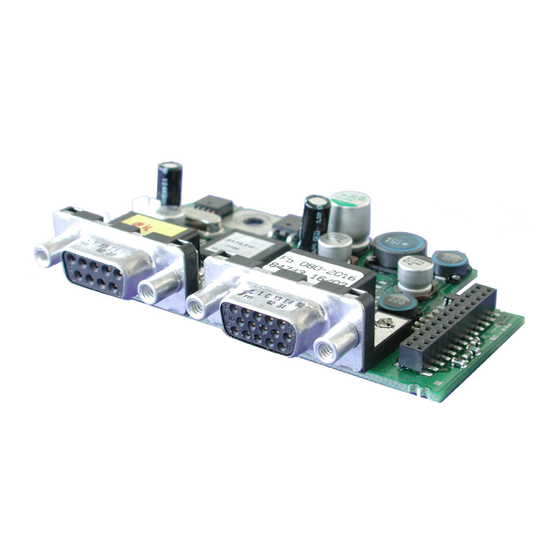
KEB COMBIVERT F5 Instruction Manual
Channel 1/2, encoder interface, hiperface variable
Hide thumbs
Also See for COMBIVERT F5:
- Applications manual (378 pages) ,
- Reference manual (349 pages) ,
- Instruction manual (196 pages)
Summary of Contents for KEB COMBIVERT F5
- Page 1 COMBIVERT INSTRUCTION MANUAL Encoder Interface Channel 1 Hiperface Channel 2 variable Mat.No. Rev. DHF5ZEM-K002...
-
Page 3: Table Of Contents
Table of Contents 1. Safety Instructions ..................4 Validity ........................4 1.2 Qualification ......................4 2. Product Description ..................5 General .......................5 Material number ....................5 Scope of delivery (option or replacement delivery) ..........5 Mechanical installation ..................6 3. Description of the Interface ................6 Voltage supply ....................6 Channel 2 ......................6 Channel 1 ......................7... -
Page 4: Safety Instructions
The used semiconductors and components of KEB are developed and dimensi- oned for the use in industrial products. If the KEB COMBIVERT is used in ma- Use under spe-... -
Page 5: Product Description
Hiperface General Each of the interface cards delivered by KEB include two interfaces. As there are numerous different combinations available each interface will be described by means of separate instructions. The instruction covers the installation of the interface card, the connection as well as the start-up of a suitable encoder. -
Page 6: Mechanical Installation
Hiperface® at channel 1 Mechanical installation All kind of works on the inverter may be carried out by authorized personnel in accordance with the EMC and safety rules only. • Switch inverter de-energized and await capacitor discharge time • Pull off operator • Remove plastic cover •... -
Page 7: Channel 1
Hiperface® at channel 1 Channel 1 3.3.1 Specifications Socket SUB-D15 Interface type Hiperface® Parameter channel EIA RS485 half duplex Process data channel 1 Vss typical (0,6…1,2V) Limiting frequency 200 kHz Increments per revolution 1…2048 Ink Input resistance 120 Ω 3.3.2 Description of X3A Figure 3.3.2 Socket X3A Attention ! Plug connector only when COMBIVERT and supply... -
Page 8: Input Signals Channel 1
Hiperface® at channel 1 3.3.3 Input signals channel 1 3.3.3.1 Process data channel Figure 3.3.3.1 Signal form A and B respectively to differential operation 360°mechanical Increments per revolution 1Vss 2,5V 2,5V 1Vss 3.3.3.2 Description of encoder signals During start-up an inquiry is permanently sent to the encoder and the absolute position is serial read out. -
Page 9: Connection Of The Encoder
REF_SIN- Data+ gray Data- pink white 7,5 V brown 3.3.5 Encoder cable KEB encoder cables are corresponding to the following specification: Signal lines 3 x (2 x 0,14 mm²) Supply lines 2 x (0,5 mm²) Particularities trailing capable, oil resistant Temperature range constant up to 80 °C Color... -
Page 10: Encoder Line Length
Supply voltage U: 7,5 V min. supply voltage U : see encoder description KEB encoder cable resistance R: 0,036 Ω/m at 0,5 mm² 3.3.7 Tested encoder The following encoders have been tested by KEB on it application: Encoder description Hiperface identifier (Ec.36) SCS 50/60 SCM 50/60 SRS 50/60... -
Page 11: Hiperface® - Parameter
Encoder signals are outside the specification (message from encoder) Encoder has internal defect (message from encoder) Encoder will be formatted. When writing an encoder with memory structures different from the KEB-definition, their memories will be re-organized in such a manner that they can be written. This procedure can take some seconds, depen- ding on the respective memory structure. New value detected, because another encoder was attached. -
Page 12: Hiperface Encoder Status
Hiperface® at channel 1 Value Description The following status messages triggers „Error Encoder 1“ (E.Enc1), if encoder data is read: KEB-reference is undefined. Memory structure of the encoder does not corre- spond to the KEB-definition and therefore data cannot be read. The encoder is defined by writing data. At F5-S the error is reset as follow: • writing a position to Ec.2. • perform a system position trimming Following status messages trigger error „Error Hybrid“ (E.HYb): 0,255 No communication between interface and control card. - Page 13 Notices GB-13...
- Page 14 Notices GB-14...
- Page 15 Notices GB-15...
- Page 16 KEB Italia S.r.l. fon: +32 5443 7860 • fax: +32 5443 7898 Via Newton, 2 • I-20019 Settimo Milanese (Milano) mail: vb.belgien@keb.de fon: +39 02 33535311 • fax: +39 02 33500790 net: www.keb.it • mail: kebitalia@keb.it KEB Power Transmission Technology (Shanghai) Co.,Ltd. No. 435 QianPu Road, Songjiang East Industrial Zone, KEB Japan Ltd. CHN-201611 Shanghai, P.R. China 15–16, 2–Chome, Takanawa Minato-ku fon: +86 21 37746688 • fax: +86 21 37746600 J–Tokyo 108-0074 net: www.keb.cn • mail: info@keb.cn...


Need help?
Do you have a question about the COMBIVERT F5 and is the answer not in the manual?
Questions and answers