
Related Manuals for GeoVision V5


Summary of Contents for GeoVision V5
- Page 1 GV-Hot Swap Surveillance System V5 (Rev. User’s Manual User’s Manual DVRHV5-UM-T...
- Page 2 Every effort has been made to ensure that the information in this manual is accurate. GeoVision, Inc. makes no expressed or implied warranty of any kind and assumes no responsibility for errors or omissions. No liability is assumed for incidental or consequential damages arising from the use of the information or products contained herein.
- Page 3 Welcome to the GV-Hot Swap Surveillance System V5 (Rev. B) User’s Manual. The Manual provides an overview of the 3U / 4U GV-Hot Swap Surveillance System V5 and its accessories. It also includes the instructions to guide you through the installation and use of the GV-Hot Swap Surveillance System V5: •...
-
Page 4: Table Of Contents
Safety Instructions ........................vi Chapter 1 Introduction ......................1 1.1 Models ........................1 1.2 Packing List ......................4 1.2.1 GV-Hot Swap DVR/NVR System V5 ............4 1.2.2 GV-Hot Swap Recording Server / Backup Center System ......5 1.3 Software License ......................7 1.3.1 GV-Hot Swap DVR/NVR System V5 ............8 1.3.2 GV-Hot Swap VMS System V5 ..............8... - Page 5 3.14.7 Redundant Power Supply .................82 3.15 System Restoration ....................85 3.15.1 Restoring the System................85 3.15.2 Configuring the GV-Hot Swap DVR/NVR V5 for PAL......87 3.16 Updating GV-Hot Swap Surveillance System V5 ..........88 Chapter 4 DVR Health Analysis ..................89 4.1 System Settings......................89 4.2 System Log......................91 4.3 Information of Your Computer System..............93...
- Page 6 C. Combining Optional Accessories................116 Warranty Requirements .....................122 Warranty Form........................124...
-
Page 7: Notice
Notice 1. The back panel of GV-Hot Swap Surveillance System V5 is subject to change without prior notice. 2. For the users of GV-Hot Swap DVR/NVR System and GV-Hot Swap VMS System, please see the User’s Manual for the hardware introduction and installation, and see the GV-DVR User’s Manual and GV-VMS User’s Manual for the software operation. -
Page 8: Safety Instructions
Safety Instructions Observe these safety instructions to help ensure against injury to yourself and damage to the product. Read all safety and installation instructions before you operate the product. Do not operate the product in high humidity areas or expose it to water or moisture. Do not put the product in an unstable, a slanting or vibrated place. -
Page 9: Chapter 1 Introduction
Chapter 1 Introduction 1.1 Models The 3U / 4U GV-Hot Swap Surveillance System V5 has the following models: - 4 / 8 / 12-channel digital video recorder - 4-Ch: Records up to 120 (NTSC) / 100 (PAL) fps at 1080p resolution... - Page 10 GV-NVRH V5 - 32-channel GeoVision IP Devices and 1 / 2 / 4 / 6 / 8 / 10 / 12 / 14 / 16 / 18 / 20 / 22 / 24 / 26 / 28 / 30 / 32-channel third-party IP devices digital...
- Page 11 - Has the options of 4U (20-bay) and 3U (16 / 8-bay) hot-swap SATA drive Backup Center System bays Note: A dongle is internally inserted in GV-SDI-204H V5, GV-5016H V5, GV-NVRH V5, Integrated Model, GV-VMS, GV-Hot Swap Recording Server System and GV-Hot Swap Backup Center System.
-
Page 12: Packing List
1.2 Packing List The GV-Hot Swap Surveillance System V5 package includes the following items. If any of the items are missing or damaged, contact your dealer to arrange a replacement. Important: Please keep the original carton and all packing materials for future shipping need. - Page 13 4. GV-Keyboard Package x1 6. Self-Stick Rubber Pad x 4 7. Quick Start Guide x 1 Note: Keyboard package is not included for 3U (16 / 8-bay) of GV-3008H V5 models, but it could be purchased as an optional accessory.
-
Page 14: Gv-Hot Swap Recording Server / Backup Center System
1.2.2 GV-Hot Swap VMS System V5 1. GV-Hot Swap VMS System V5 x 1 2. AC Power Cord x 1 4. GV-IR Remote Control x 1 3. GV-Keyboard Package x 1 5. Self-Stick Rubber Pad x 4 6. Quick Start Guide x 1 1.2.3 GV-Hot Swap Recording Server / Backup Center System... -
Page 15: Software License
Introduction 1.3 Software License The following Maximum License is available as a paid service. The license is based on your requirements for the number of connection channels. The USB dongle for software license will be inserted to the system before shipment. -
Page 16: Gv-Hot Swap Dvr/Nvr System V5
1.3.1 GV-Hot Swap DVR/NVR System V5 32 channels from GV-IP Devices Free License 32 channels from third-party IP devices Maximum License Increment for Each 1 to 32 third-party IP cameras at an increment of 2 License Optional Combinations Dongle Type Internal 1.3.2 GV-Hot Swap VMS System V5... -
Page 17: Recommended Hard Disks
Introduction 1.4 Recommended Hard Disks For system efficiency, we recommend the following enterprise level hard disk drives. Avoid using desktop level or green HDD which may affect system efficiency. • WD RE series • Seagate Constellation ES.3 series • HGST Ultrastar series... -
Page 18: Options
1.5 Options Optional devices can expand your GV-Hot Swap Surveillance System V5 ’s capabilities and versatility. For details on combining options for your system, see Appendix C. Combining Optional Accessories. This card can take the video signal from the GV-Hot Swap Surveillance System V5 and then split it into 16 signals while maintaining video quality. - Page 19 Introduction GV-Joystick facilitates the PTZ camera control. It can be either plugged into the GV-Hot Swap Surveillance System V5 for GV-Joystick independent use or connected to GV-Keyboard to empower the operation. However, this device can only work on GV-System version 8.2 or later.
- Page 20 1. The GV-IO 12-In and GV-IO 12-Out Cards must work and be purchased together. 2. The optional accessories will be built in the GV-Hot Swap Surveillance System V5 (Rev. B) and tested before shipment. Opening the case and installing the accessories yourself will void the warranty.
-
Page 21: Chapter 2 Overview
Overview Chapter 2 Overview 2.1 Front View 2.1.1 4U (20 Bay) Models Figure 2-1 No. Name Name USB Port x 2 Reset Button LED Panel DVD(±) RW Drive (See 2.2 LED Panel View for details.) DVD(±) RW Drive Activity LED HDD Group A DVD-eject button HDD Group B... -
Page 22: U (16 / 8-Bay) Models
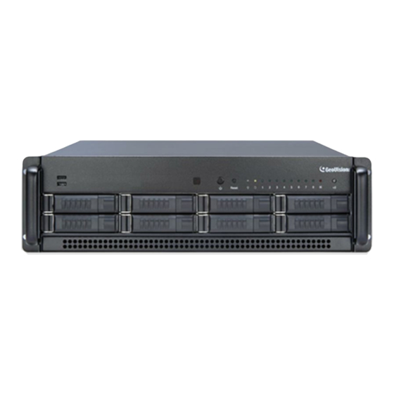
2.1.2 3U (16 / 8-Bay) Models 2.1.2.1 16-Bay Models Figure 2-2 No. Name Name DVD(±) RW Drive Reset Button LED Panel DVD(±) RW Drive Activity LED (See 2.2 LED Panel View for details.) DVD-eject button HDD Group A USB Port x 2 HDD Group B Built-in GV-IR Remote Control HDD Group C... -
Page 23: Led Panel View
HDD Group C LED HDD Group D LED The LED shines and the system sounds on if one fan System Alert LED stops or the GV-Hot Swap Surveillance System V5 is overheated. Alert LED (reserved) Press this button to silence the alarm when the System Alarm Mute Button Alert LED shines and the system sounds. -
Page 24: 8-Bay) Models
The LEDs of HDD 1 ~ 8 shine when the power is on. The LED shines and the system sounds on if one fan System Alert LED stops or the GV-Hot Swap Surveillance System V5 is overheated. Press this button to silence the alarm when the System Alarm Mute Button Alert LED shines and the system sounds. -
Page 25: Rear View
Overview 2.3 Rear View 2.3.1 4U (20-Bay) Models 2.3.1.1 GV-SDI-204H V5 Figure 2-6 No. Name No. Name AC Power Switch RJ-11 Port AC Power Input (Full Range) I/O Terminal Block USB 2.0 Port x 2 BNC Video 5-8 (For 8-Ch Model Only) - Page 26 D-Type Audio and Video 16-32 (For 32-Ch Model Only) I/O Terminal Block RJ-11 Port * The RS-485± ports are not functional on GV-5016H V5. For details on the other features of the motherboard and power supply on the rear panel, see Figure 2-6.
- Page 27 Overview 2.3.1.3 GV-3008H V5 18 17 Figure 2-8 Name No. Name PS/2 Keyboard Port I/O and RS-485± Terminal Block I D-Type Audio and Video 9-16 S/PDIF Port (For 16-Ch Model Only) Clear CMOS Switch D-Type Audio and Video 1-8 USB 2.0 Port x 4...
- Page 28 2.3.1.4 GV-1480H / GV-1240H / GV-1120H V5 Figure 2-9 No. Name DVI Video 1-16, DVI Audio 1-16 DVI Video 17-32, DVI Audio 17-32 (For 32-Ch Model Only) I/O and RS-485± Terminal Block RJ-11 Port For details on other features of the motherboard and power supply on the rear panel, see...
- Page 29 Overview 2.3.1.5 GV-900H V5 Figure 2-10 No. Name DVI Video 1-16 with Audio 1-8 DVI Video 17-32 with Audio 17-24 (For 32-Ch Model Only) I/O and RS-485± Terminal Block RJ-11 Port For details on the other features of the motherboard and power supply on the rear panel, see...
- Page 30 2.3.1.6 GV-800H V5 Figure 2-11 No. Name DVI Video 1-16 and Audio 1-4 DVI Video 17-32 and Audio 17-20 (For 32-Ch Model Only) I/O and RS-485± Terminal Block RJ-11 Port For details on the other features of the motherboard and power supply on the rear panel, see...
- Page 31 Gigabit Ethernet Port I/O Terminal Block RJ-11 Port * The RS-485± ports are not functional on GV-NVRH V5 / GV-VMSH V5. For details on the other features of the motherboard and power supply on the rear panel, see Figure 2-6.
- Page 32 2.3.1.8 GV-Hot Swap Recording Server System Figure 2-13 For details on the other features of the motherboard and power supply on the rear panel, see Figure 2-6. 2.3.1.9 GV-Hot Swap Backup Center System Figure 2-14 For details on the other features of the motherboard and power supply on the rear panel, see Figure 2-6.
-
Page 33: U (16 / 8-Bay) Models
Overview 2.3.2 3U (16 / 8-Bay) Models 2.3.2.1 GV-SDI-204H V5 Figure 2-15 No. Name No. Name AC Power Input (Full Range) I/O Terminal Block USB 2.0 Port x 2 BNC Video 5-8 (For 8-Ch Model Only) DVI-DL Output (DVI-D Signal Only) -
Page 34: No. Name
D-Type Audio and Video 16-32 (For 32-Ch Model Only) I/O and RS-485± Terminal Block RJ-11 Port * The RS-485± ports are not functional on GV-5016H V5. For det ails on the other features of the motherboard and power supply on the rear panel, see Figure 2-15. -
Page 35: Ac Power Input (Full Range)
Overview 2.3.2.3 GV-3008H V5 19 18 9 10 Figure 2-17 No. Name Name AC Power Input (Full Range) I/O and RS-485± Terminal Block PS/2 Keyboard Port D-Type Audio and Video 9-16 (For 16-Ch Model Only) S/PDIF Port Clear CMOS Switch D-Type Audio and Video 1-8 USB 2.0 Port x 2... -
Page 36: Figure
2.3.2.4 GV-1480H / GV-1240H / GV-1120H V5 Figure 2-18 No. Name DVI Video 1-16, DVI Audio 1-16 DVI Video 17-32, DVI Audio 17-32 (For 32-Ch Model Only) I/O and RS-485± Terminal Block RJ-11 Port For details on the other features of the motherboard and power supply on the rear panel, see... - Page 37 Overview 2.3.2.5 GV-900H V5 Figure 2-19 No. Name DVI Video 1-16 with Audio 1-8 DVI Video 17-32 with Audio 17-24 (For 32-Ch Model Only) I/O and RS-485± Terminal Block RJ-11 Port For details on the other features of the motherboard and power supply on the rear panel, see...
- Page 38 2.3.2.6 GV-800H V5 Figure 2-20 No. Name DVI Video 1-16 and Audio 1-4 DVI Video 17-32 and Audio 17-20 (For 32-Ch Model Only) I/O and RS-485± Terminal Block RJ-11 Port For details on the other features of the motherboard and power supply on the rear panel, see...
-
Page 39: I/O Terminal Block
Gigabit Ethernet Port I/O Terminal Block RJ-11 Port * The RS-485± ports are not functional on GV-NVRH V5 / GV-VMSH V5. For details on the other features of the motherboard and power supply on the rear panel, see Figure 2-15. - Page 40 2.3.2.8 GV-Hot Swap Recording Server System 16 / 8-Bay Model Figure 2-22 For details on the other features of the motherboard and power supply on the rear panel, see Figure 2-15.
- Page 41 Overview 2.3.2.9 GV-Hot Swap Backup Center System 16 / 8-Bay Model Figure 2-23 For details on the other features of the motherboard and power supply on the rear panel, see Figure 2-15.
-
Page 42: Integrated Models
2.3.3 Integrated Models For 3U (8-bay) models, you can have up to two GV-SDI-204 Cards with one GV-Video Capture Card (GV-5016 / GV-1480B / GV-1240B / GV-1120B / GV-900A / GV-800B). For 4U (20-bay) and 3U (16-bay) models, you can combine one GV-SDI-204 Card with one GV-Video Capture Card listed above. -
Page 43: Chapter 3 Getting Started
This section describes all the equipments required to program and operate the GV-Hot Swap Surveillance System V5. Up to 3 monitors can be connected to the System. 3.1.1 All Models (excluding GV-3008H V5) Here we use the 4U (20-bay) models of GV-1480H / GV-1240H / GV-1120H V5 (32-Ch) as the example. Figure 3-1 1. -
Page 44: Vga Monitor Output
Connecting to 3 Monitors You can connect up to 3 monitors to the ports labeled below on the back panel of the GV-Hot Swap Surveillance System V5. Here we use the 3U (16 / 8-bay) model as the example. VGA Monitor Output... -
Page 45: Gv-3008H V5
Getting Started 3.1.2 GV-3008H V5 Here we use the 3U (8-bay) model as the example. Figure 3-3 1. Using the VGA cable supplied by the monitor manufacturer, connect the VGA monitor. 2. Using the supplied power cord, connect one end to the AC input and the other end to the power outlet. - Page 46 Connecting to 2 Monitors You can connect up to 2 monitors to 2 of the 3 ports labeled below on the back panel of the GV-Hot Swap Surveillance System V5. Here we use the 3U (8-bay) model as the example. VGA Monitor Output...
-
Page 47: Turning On The Power
3.2 Turning on the Power Once the above hardware is properly connected, it is the time to turn on the GV-Hot Swap Surveillance System V5. To turn on the power, follow these steps: 1. Turn on the monitor. Power On Figure 3-5 2. - Page 48 After this is finished, GV-Hot Swap DVR System V5 brings you to the main screen display of 8, 16 or 32 cameras. GV-Hot Swap NVR System V5 pops up GV-IP Device Utility to detect IP devices under the same LAN.
-
Page 49: Installing The Hard Drive
Getting Started 3.3 Installing the Hard Drive The GV-Hot Swap Surveillance System V5 uses SATA hard drives for video and audio data storage. Before recording, be sure to install your hard drives. 1. Make sure the HDD Activity LED is off before you install the hard drive. -
Page 50: Windows Setup Installation
3.4 Windows Setup Installation The Windows setup is preparing your computer for first use. 1. After the Windows starts, this setup screen appears. Select your language and click Next to continue. Figure 3-11 2. Select your Country or region, Time and currency, and Keyboard layout and click Next to continue. - Page 51 Getting Started 3. Type a user name for your account and then click Next to continue. Figure 3-13 4. It is recommended that you create a password for your account and then click Next to continue. Figure 3-14...
- Page 52 5. Since no license terms are specified, the page is left blank intentionally. Select I accept the license terms and click Next to continue. Figure 3-15 6. It is recommended that you choose Ask me later to disable Windows automatic updates. Figure 3-16...
- Page 53 Getting Started 7. Choose the correct Time zone, Date, and Time and click Next to continue. Figure 3-17 8. You may see the below screen if a network connection is detected by your computer. It is recommended that you select the Work network for security purposes and click Next. Figure 3-18 When the above setup process is complete, Windows will finalize your settings automatically in the background and restart.
-
Page 54: Formatting The Hard Drive
3.5 Formatting the Hard Drive After installing hard drives to your system, you will need to format them before use. • For GV-Hot Swap DVR/NVR V5 and GV-Hot Swap VMS V5, follow the steps below from step 1. • For GV-Hot Swap Recording Server System and GV-Hot Swap Backup Center System, right-click My Computer, select Manage, select Disk Management and then skip to step 1. - Page 55 Getting Started 3. On the main page of Disk Management, the Initialize Disk dialog box appears for the new drive. Click the created disk and select a partition style. Figure 3-21 4. Click OK. The created disk is successfully initialized. 5.
- Page 56 6. The New Simple Volume Wizard appears. Click Next to continue. Figure 3-23 7. The default partition size is the same as the maximum disk space. Make changes if necessary. Click Next to continue. Figure 3-24...
- Page 57 Getting Started 8. Assign a drive path that is not in use by other devices, and click Next to continue. Figure 3-25 Note: The default drive path starts from F:\. 9. Type a name in the Volume label box, ex. HDD1, and click Next to continue. Figure 3-26...
- Page 58 10. When the formatting is complete, click Finish to close the wizard. Figure 3-27 11. When the drive is successfully initialized, partitioned, and formatted, its status description should display “Healthy.” Figure 3-28...
-
Page 59: Adding The Hard Drive To The Recording Path
Note the function is not available for GV-Hot Swap Recording Server System / GV-Hot Swap Backup Center System. For GV-Hot Swap DVR/NVR V5 and GV-Hot Swap VMS V5, you need to add the formatted hard drives to the recording path before recording. - Page 60 3. If a hard drive is not inserted, follow these steps: A. Insert a hot-swap hard drive or plug a portable hard drive to the GV-Hot Swap DVR/NVR This dialog box appears. Figure 3-30 B. Select Add to recording path, and select the storage group from the drop-down list. Note: Storage 1 is the default storage group.
- Page 61 Getting Started 6. To add another formatted hard drive for storage, repeat the above steps. For details on using Hot Swap HDD Tool, see Chapter 11, GV-DVR User’s Manual (GV-Desktop > Program button > User Manual).
-
Page 62: Gv-Hot Swap Vms V5
3.6.2 GV-Hot Swap VMS V5 1. On the GV-VMS, click Home , select Toolbar , select Configure , select System Configure, and click Record Setting. The Record Setting dialog box appears. 2. Click the Arrow button next to Storage. Figure 3-32 3. - Page 63 Getting Started 4. To create a new storage group, click the Add button in the top-left corner. Figure 3-34 5. To add a recording folder to a newly created storage group, repeat step 3. 6. Select Keep Days and specify the number of days to keep the video files in storage. Note: If the designated storage space is not big enough to keep all video files for the defined days, the Recycle Threshold setting will override the Keep Days setting.
-
Page 64: Setting Up On Screen Led Panel
Note the function is not supported by GV-Hot Swap Recording Server System / GV-Hot Swap Backup Center System. For GV-Hot Swap DVR/NVR V5 and GV-Hot Swap VMS V5, a LED panel on the screen provides a quick indication of the activity status of hard disk drives. - Page 65 Synchronize the LED Panel with the LED Device on GV-Hot Swap DVR/NVR: When this option is enabled, the LED device installed on the front door of the GV-Hot Swap DVR/NVR V5 and GV-Hot Swap VMS V5 will synchronize with the LED panel on the screen.
-
Page 66: Replacing The Hard Drive
3.8 Replacing the Hard Drive You can replace the hard drive in the Hot Swap Drive Bay without shutting down the GV-Hot Swap Surveillance System V5. 1. Make sure the HDD Activity LED (No. 2, Figure 2-4) is off. 2. Slide the release latch to the right. The drawer handle pops up. -
Page 67: Configuring The Ip Address
• 192.168.0.200 • 192.168.0.201 (Only available for GV-3008H V5, GV-NVR V5, GV-Hot Swap VMS V5, GV-Hot Swap Recording Server System and GV-Hot Swap Backup Center System) • 192.168.0.202 (Only available for GV-Hot Swap Recording Server System and GV-Hot Swap Backup Center System) •... - Page 68 To change the static IP addresses or to enable dynamic IP address, follow the steps below. • For GV-Hot Swap DVR/NVR V5 and GV-Hot Swap VMS V5, start from step 1. • For GV-Hot Swap Recording Server System and GV-Hot Swap Backup Center System, select Control Panel and skip to step 3.
- Page 69 Getting Started 5. Select Internet Protocol Version 4 (TCP/IPv4) and then click Properties. Figure 3-40 6. Select Use the following IP address and type the new IP information in the fields or select Obtain an IP address automatically to enable dynamic IP address. Figure 3-41 7.
-
Page 70: Exiting To Windows
Note this function is not available for GV-Hot Swap Recording Server System / GV-Hot Swap Backup Center System. GV-Hot Swap DVR/NVR V5 / GV-Hot Swap VMS V5 is protected by GV-Desktop that is limited to run the selected programs. If you need to exit to Windows desktop, follow these steps. -
Page 71: Returing To Gv-Desktop
Note this function is not available for GV-Hot Swap Recording Server System / GV-Hot Swap Backup Center System. To return to GV-Desktop, click the Windows Start button, point to All Programs, click GV-DVR/NVR V5, GV-DVR, GV-NVR or GV-VMS and click Key Lock Utility. Figure 3-43 Windows 7 desktop... -
Page 72: Multi View Display
Note this function is not available for GV-Hot Swap Recording Server System / GV-Hot Swap Backup Center System. 3.12.1 GV-Hot Swap DVR/NVR System V5 You can display multiple views on up to 6 monitors simultaneously, one for live viewing and the others for playback or other operation without obstructing surveillance scene, with GV-DVD/NVR V5. - Page 73 Getting Started 8. Go to the system folder and locate DMPOS.exe. Figure 3-45 9. Run DMPOS.exe. This dialog box appears. Figure 3-46 10. In the Screen Setup tab, select a desired monitor display mode, such as Twin View or Three View, from the Displayer Mode drop-down list. 11.
-
Page 74: Gv-Hot Swap Vms System V5
3.12.2 GV-Hot Swap VMS System V5 You can customize the display settings of GV-VMS. Click Home , select Toolbar select Configure , select System Configure, and click Set Position. This dialog box appears. The right side of the dialog box is only available when multiple monitors are installed. -
Page 75: Digital Martrix
Getting Started 3.13 Digital Matrix Note this function is not available for GV-Hot Swap VMS System V5, GV-Hot Swap Recording Server System / GV-Hot Swap Backup Center System. To create more screen space to display multiple channels, such as 32 channels, Digital Matrix is thus introduced to provide a way to view and manage multiple monitor displays. -
Page 76: Setting Live View
3.13.2 Setting Live View You can set different live views and screen divisions for each monitor. 1. On the main screen, click the Configure button, click Accessories, and select Digital Matrix Setting. This dialog box appears. Figure 3-49 2. Use the Display list to select the monitor to be configured. 3. -
Page 77: Setting Scanned
Getting Started 3.13.3 Setting Scanned Pages You can set up to 16 scanned pages with different screen divisions and channels for each monitor. 1. Use the Display list to select the monitor to be configured. 2. In the upper-left column, expand the Matrix folder tree, and then click Page 1. This page appears. -
Page 78: Setting Pop-Up Alert
3.13.4 Setting Pop-up Alert You can be alerted by pop-up live videos when motion is detected or I/O devices are triggered. 1. Use the Display list to select the monitor to be configured. 2. In the upper-left column, click Event Popup. This page appears. Figure 3-51 Motion Trigger: The live video of selected cameras pops up when motion is detected. -
Page 79: Setting Pop-Up Positions
Getting Started 3.13.5 Setting Pop-up Positions When you select Random Position of Camera, you can decide the positions for pop-up cameras. Fixed Position of Camera: The cameras pop up in their assigned positions. To assign positions, select Screen Division. Then drag and drop the cameras number to the desired potions on the divisions. -
Page 80: Setting Live View With Pop-Up Alert
3.13.6 Setting Live View with Pop-up Alert You can set a different live view mode with pop-up alert together for each monitor. When alert events occur, the live video of the associated camera will pop up on the assigned monitor to replace its live view mode. -
Page 81: Extended Installation
The GV-Keyboard is designed to operate the GV-Hot Swap DVR/NVR V5 and GV-Hot Swap VMS V5 exclusively. Using the USB cable supplied with the GV-Keyboard, plug one end into the GV-Keyboard and the other end into any one of the USB ports on the back of the GV-Hot Swap DVR/NVR V5 and GV-Hot Swap VMS V5;... -
Page 82: Gv-Ir Remote Control
After the GV-Hot Swap DVR/NVR V5 / GV-Hot Swap VMS V5 starts up, the Keyboard controller dialog box will automatically appear and start service. The dialog box will run in the background and closing the dialog box will cause GV-Keyboard to disconnect. -
Page 83: I/O Devices
Note that this function is not supported by GV-Hot Swap Recording Server System / GV-Hot Swap Backup Center System. The GV-Hot Swap DVR/NVR V5 / GV-Hot Swap VMS V5, with built-in GV-NET/IO Card, provides 4 alarm outputs and 4 sensor inputs. -
Page 84: Ptz Domes
Figure 3-56 Note: The built-in RS-485± functions are not available for GV-SDI-204H V5, GV-5016H V5 and GV-NVRH V5. However, you can still use one of the methods below to connect RS-485 devices: Connect the GV-Hot Swap DVR/NVR V5 to IP devices, such as GV-Video Server or GV-Compact DVR, for accessing the PTZ functions over the Internet. -
Page 85: Graphic Cards
VGA ports. Up to 3 monitors can be connected to the System. With 1 or 2 optional Graphic Cards installed in the GV-Hot Swap Surveillance System V5, you can choose 2 of 3 ports from each card and use all the 3 display ports on the motherboard to connect up to 7 monitors for display. - Page 86 GV-800H V5 GV-NVRH V5 / GV-VMSH V5 GV-Hot Swap Backup Center System GV-Hot Swap Recording Server System Note: GV-3008H V5 models do not support optional graphic cards. For details on combining options for your system, see Appendix C. Combining Optional Accessories.
- Page 87 Getting Started 5 Monitors When a single Graphic Card is installed, up to 5 monitors can be connected. Connect all display ports on the motherboard and choose 2 of 3 ports from the Graphic Card for display connections. Figure 3-57 7 Monitors When dual Graphic Cards are installed, up to 7 monitors can be connected.
-
Page 88: Gigabit Network Cards
3.14.6 Gigabit Network Cards The GV-Hot Swap Surveillance System V5 comes with at least one onboard gigabit port. With 1 or 2 optional Network Cards installed, the System can support up to 5 gigabit ports. The number of optional Network Cards supported varies with different models and the number of GV-Capture Cards installed. - Page 89 3U (16-bay) models with 2 built-in GV-Capture Cards or 3 built-in GV-SDI-204 Cards. 2. For the GV-NVRH V5 / GV-VMSH V5 / GV-Hot Swap Backup Center System / GV-Hot Swap Recording Server System 4U (20-bay) and 3U (16-bay) models to support 5 ports requires replacing the original single network card(s) with a (maximum of 2) dual network card(s) due to limited space of the expansion slots.
-
Page 90: Redundant Power Supply
The Redundant Power Supply comes with 2 modules for 3U models and 3 modules for 4U models. Each module shares the loading of the power supply. When one of the modules is down, the other module(s) can still support full power for the GV-Hot Swap Surveillance System V5. 4U models Figure 3-59... - Page 91 Getting Started The LED Indicators 4U models Figure 3-61 3U models Figure 3-62 LED Indicators Color Description Glows when the power input is properly Ready LED Orange connected to the power supply. Glows when the Redundant Power Access LED Green Supply is functioning.
- Page 92 To stop the ringing alarm sound, press the red button. To remove the module from GV-Hot Swap Surveillance System V5, push the release latch and pull out the entire module with the handle at the same time.
-
Page 93: System Restoration
Note: After recovery, you need to re-install all settings and passwords. But the recovery will not delete your recording files saved on the GV-Hot Swap Surveillance System V5 since it only reformats the partition C and all of your files are still stored on other partitions. - Page 94 6. When this screen appears, click the Recovery button. Once the restoration is complete, click Quit to leave the recovery system and restart the Windows automatically. Figure 3-66 For the recovery system part, see steps 1 – 6 in 3.4 Windows setup installation.
-
Page 95: Configuring The Gv-Hot Swap Dvr/Nvr V5 For Pal
The default video standard after the system restoration is set to NTSC. If the video standard in your country is PAL, remember to configure the GV-Hot Swap DVR/NVR V5 for PAL. 1. Click the Configure button, point to A/V Setting, and then select Video Source. -
Page 96: Updating Gv-Hot Swap Surveillance System V5
3.16 Updating GV-Hot Swap Surveillance System V5 GeoVision will periodically update the GV-System Software (Multicam Surveillance System). If you like to update your GV-Hot Swap Surveillance System V5, contact your dealer for more information or check software update news at our website:... -
Page 97: Chapter 4 Dvr Health Analysis
Swap Backup Center System. GeoVision offers health analysis to GV-Hot Swap DVR/NVR System V5 and GV-Hot Swap VMS System V5. The service is intended to give diagnosis for early and immediate detection of problems. It is recommended to have the health analysis during the first week after you install the GV-Hot Swap DVR/NVR System V5 / GV-Hot Swap VMS System V5 and then have the checkup every three months. - Page 98 2. Select Backup MultiCam Settings or Restore Defaults, and select Backup Current System. This dialog box appears. Figure 4-2 3. Press the Next Step button to back up all your system settings. The Save As dialog box appears. 4. Select the destination drive to store the backup file. When the backup is complete, this message “Successfully Backup MultiCam System Settings”...
-
Page 99: System Log
Please provide the sys*.mdb files of system log. The files by default are saved at D:\GV folder\database (GV-Hot Swap DVR/NVR System V5) or D:\Log\Database (GV-Hot Swap VMS System V5). If you have modified the default location, you can check the path by the following steps: For GV-Hot Swap DVR/NVR System V5 1. - Page 100 For GV-Hot Swap VMS V5 1. Click ViewLog button , select Toolbar , select Configure , and then select System Log Setting. This dialog box appears. Figure 4-4 2. The location of your system log is listed after Log Path.
-
Page 101: Information Of Your Computer System
DVR Health Analysis 4.3 Information of Your Computer System To get the information of your computer system, please follow the steps below to install the free software PC WIZARD. By using the software, the following computer information can be easily collected and saved for analysis: Processor: includes Type, Frequency, Data Cache L1, Trace Cache L1, Cache L2, Voltage, Processor Temperature, FPU Coprocessor. - Page 102 4. In the Save As dialog box, select Format HTML and click OK. Figure 4-6 5. Select the Save location, type the file name, and then click Save to save the Processor information as HTML file. 6. Repeat Steps 3-5 to save the Drives information as HTML file. 7.
-
Page 103: Health Analysis Form
4.4 Health Analysis Form Please send the related data for analysis along with this Health Analysis Form to dvrsystem@geovision.com.tw. Health Analysis of GV-Hot Swap DVR/NVR System V5 or GV-Hot Swap VMS System V5 Contact Person: Title: Company Name: Telephone: (O) -
Page 104: Chapter 5 Troubleshooting
A portable 2.5'' HDD connected to the front panel cannot be detected. When the portable 2.5” HDD connected to a GV-Hot Swap Surveillance System V5 cannot be detected, try this step: Use a dual head USB cable and insert both heads to the USB ports on the GV-Hot Swap Surveillance System V5 front panel as illustrated below. - Page 105 Figure 5-2 2. Make sure that the power cord is properly connected to both GV-Hot Swap Surveillance System V5 and power outlet. If you are using a power strip, make sure that the strip is powered on. 3. If the problem persists, consult your dealer.
- Page 106 GV-Hot Swap Surveillance System V5’s hard disk corrupts. If you are experiencing file system corruption problems, such as lost clusters, cross-linked files or invalid files or directories, try these steps: 1. Use the HD Tune utility to scan the hard disk for errors. Follow these steps: A.
- Page 107 Troubleshooting 2. If the HD Tune utility does not find any defects, use the Windows built-in utility to attempt to fix the errors. Follow these steps: A. On the GV-Desktop, click the Programs button, and select Disk Management. See Figure 3-11. B.
- Page 108 GV-Hot Swap DVR/NVR V5 has video and/or audio lost. If your GV-Hot Swap DVR/NVR V5 fails to show video, audio or both, try these steps: 1. Check the video/audio connection. Make sure one end of the D-type video/audio cable is securely connected to the video/audio device, and the other end to the video/audio port of the GV-Hot Swap DVR/NVR V5.
-
Page 109: Specifications
Specifications Specifications GV-Hot Swap DVR/NVR System V5 / GV-Hot Swap VMS System V5 (Rev. B) System (all models except GV-3008H V5) Model 20-bay 16-bay 8-bay Intel Core i7 Processor 4 GB Dual Channels (GV-DVR/NVRH V5); 8 GB Dual Channels (GV-VMSH V5) - Page 110 System (GV-3008H V5) Model 20-bay 16-bay 8-bay AMD 6-Core Processor 4 GB Dual Channels 64-bit Windows Embedded Standard 7 DirectX 20 (3.5" HDD) 16 (3.5" HDD) 8 (3.5" HDD) No. of HDD 500 GB (3.5” HDD) 500 GB (2.5” HDD) 500 GB (3.5”...
- Page 111 Specifications V ideo and Audio (GV-5016H / GV-1480H / GV-1240H / GV-1120H / GV-900H / GV-800H V5) GV-5016H GV-1480H GV-1240H GV-1120H GV-900H GV-800H Model NTSC, PAL Video Standard 16 / 32 channels Video Input 0.5 ~ 1.5 Vp-p (± 10%) composite, 75 Ω...
- Page 112 1080p 640 x 360 720p 960 x 540, 480 x 270 1080i Note: Only 3U (8-bay) models support 12 channels of video input. Video and Audio (GV-NVRH V5) Model GV-NVR (GV) GV-NVR (3 Party) 32 channels 1, 2, 4, 6, 8, 10, 12, 16, 18, 20, 22, 24, 26, 28, 30, 32 channels...
- Page 113 Monitoring Environment Mobile device (Android Smartphone and tablet; iPad, iPhone and iPod Touch) Max. 32-channel Multi Views WebCam Live View (Max. 200 channels connecting to GV-Hot Swap DVR/NVR V5) System Monitoring and Recovery Automatic restart after power outage Power Restoration...
- Page 114 2-pin terminal RS±485 for PTZ Control Note: 1. The built-in RS±485 for PTZ Control is not available for GV-SDI-204H V5, GV-5016H V5 and GV-NVRH V5. 2. 32-port audio input is not supported for GV-3008H V5. Environment 0 ~ 45 °C / 32 ~ 113 °F Operating Temp.
- Page 115 Specifications Hard Disk Requirements The total of recording frame rates that you can assign to a single hard disk is listed as below: Frame rate limit in a single hard disk when connecting to analog cameras Analog Cameras / SW Compression MPEG4 Video Resolution NTSC...
- Page 116 GV-Hot Swap Recording Server System V5 (Rev. B) System Model 20-bay 16-bay 8-bay Intel Core i7 Processor 16 GB Dual Channels 64-bit Windows Embedded Standard 7 DirectX 20 (3.5" HDD) 16 (3.5" HDD) 8 (3.5" HDD) No. of HDD 500 GB (3.5” HDD) 500 GB (2.5”...
-
Page 117: Software Specifications
Specifications Software Specifications Number of IP Video 128 channels Device Connections Number of Remote Client 300 channels Connections Active Connections Yes (only for GV-IP Devices) Passive Connections 3rd Party IP Cameras Support Single live view, multi-channel live view Live Viewing Yes (up to 128 channels) Recording HTTP, HTTPS, TCP, UDP, SMTP, UPnP, DynDNS, RTSP, PSIA, ONVIF... - Page 118 HDD Capacity The amount of time GV-Hot Swap Recording Server System can record before recycling begins is listed below. HDD capacity HDD Capacity Amount of time each model can Frame Resolution Bit rate required for for each model record before recycling begins rate recording 128ch 8-bay (48 TB)
- Page 119 Specifications GV-Hot Swap Backup Center System V5 (Rev. B) System Model 20-bay 16-bay 8-bay Intel Core i7 Processor 4 GB Dual Channels 64-bit Windows Embedded Standard 7 DirectX 20 (3.5" HDD) 16 (3.5" HDD) 8 (3.5" HDD) No. of HDD 500 GB (3.5”...
- Page 120 Software Specifications 200 units of GV-System and GV-IP Devices; Number of hosts 3 units of GV-Recording Server 100 in total including Supervisors and Users Number of user accounts Yes (for GV-System and GV-IP Devices) Backup schedule 10 rules for working and non-working days independently for GV-System and Backup rules GV-IP Devices Resuming backup after...
-
Page 121: Appendix
Appendix Appendix A. Supported IP Devices This list provides the supported IP device brands. For detailed information on the supported IP devices, refer to Supported IP Camera List on GeoVision’s Website: http://www.geovision.com.tw/english/4_21.asp GeoVision ACTi Arecont Vision AXIS Bosch Canon D-Link... -
Page 122: Assigning Network Cards
IP addresses you have set up. For GV-3008H V5, the recommended network allocation is illustrated as below. The first network card can receive up to 16 IP channels in 2 M resolution, and transmit up to 68 channels with 34 channels in 2 M resolution and 34 channels in D1 resolution. - Page 123 Appendix For GV-NVRH V5, the recommended network allocation is illustrated as below. The first network card can receive up to 32 IP channels in 2 M resolution, and transmit up to 32 in 2 M resolution. The second network card can transmit up to 64 channels in 2 M resolution.
- Page 124 Graphic Cards, Network Cards and RAID Card columns. For example: the GV-SDI-204H V5 3U (8-bay) models with 1 built-in video capture card has an option of choosing either one of optional accessories with a Yes listed under the Graphic Cards, Network Cards and RAID Card columns OR A + B / A + C / A + D / B + D / C + D / A + B + D.
- Page 125 B + D or GV-1120H V5 C + D Choose one OR combine A + E or GV-NVRH V5 / Default B + E or GV-VMSH V5 C + E or D + E or A + B + E...
- Page 126 4U (20-bay) and 3U (16-bay) models Graphic Network Cards Cards Built-in Video Monitors Gigabit Ports Supported Models Options RAID Card Capture Supported Cards Choose GV-Hot Swap one OR Default Default Default Backup Center combine System A + B Choose one OR GV-Hot Swap combine Default...
- Page 127 GV-SDI-204H V5 A + B + D Choose one OR combine Yes (D) A + D or B + D or C + D Choose one OR combine GV-1480H / A + B or 1240H / 1120H V5 B + C...
- Page 128 Choose one OR combine A + B or A + C or Yes (D) A + D or GV-5016H V5 / B + D or GV-900H V5 / C + D or GV-800H V5 A + B + D Choose...
- Page 129 B. 3U (16-bay) and 4U (20-bay) models with 2 built-in GV-1480 / 1240 / 1120 Cards 3. For the GV-NVRH V5 / GV-Hot Swap Backup Center System / GV-Hot Swap Recording Server System 4U (20-bay) and 3U (16-bay) models to support 5 gigabit ports requires replacing the original single network card with 2 dual network cards due to limited space of the expansion slots.
- Page 130 To validate your purchase, you shall complete the online Product Registration within 30 days from the date of purchase at http://www.geovision.com.tw/english/4_6.asp. Or click GeoVision Online Registration in My Favorite for a direct link. If you fail to complete the Product Registration, the warranty period will start from the date of shipment.
- Page 131 2. Securely pack the product in its original carton using the original packing material, or in equivalent packaging. 3. The product shall be returned to GeoVision, Taiwan at your expense for shipping and insurance costs. BEFORE YOU DELIVER YOUR GV-HOT SWAP DVR/NVR SYSTEM V5, GV-HOT SWAP RECORDING SERVER SYSTEM AND GV-HOT SWAP BACKUP CENTER SYSTEM FOR WARRANTY SERVICE, IT IS YOUR RESPONSIBILITY TO BACK UP YOUR DATA.
- Page 132 Warranty Form Thank you for purchasing the GV-Hot Swap Surveillance System V5. To help us validate your purchase and better serve you in the future, please go to http://www.geovision.com.tw/english/4_6.asp or click GeoVision Online Registration in My Favorite for a direct link to register online within 30 days from the date of purchase. Please keep this copy for your records.
- Page 133 Warranty Form Bay Option 20 Bays 16 Bays 8 Bays Bar Code: Shipment Date: GeoVision, Inc. 9F, No. 246, Sec. 1, Neihu Rd., Neihu District, Taipei, Taiwan Tel: +886-2-8797-8377 Fax: +886-2-8797-8335 Email: sales@geovision.com.tw dvrsystem@geovision.com.tw http://www.geovision.com.tw...
Need help?
Do you have a question about the V5 and is the answer not in the manual?
Questions and answers