Table of Contents
Advertisement
Quick Links
Advertisement
Table of Contents

Related Manuals for GeoVision GV-Hot Swap V5 Series


Summary of Contents for GeoVision GV-Hot Swap V5 Series
- Page 1 GV-Hot Swap Surveillance System V5 (Rev.E) User’s Manual DVRHV5E-UM-AA...
- Page 2 Every effort has been made to ensure that the information in this manual is accurate. GeoVision, Inc. makes no expressed or implied warranty of any kind and assumes no responsibility for errors or omissions. No liability is assumed for incidental or consequential damages arising from the use of the information or products contained herein.
- Page 3 User’s Manual for GV-Hot Swap Surveillance System V5 (Rev.E) Welcome to the GV-Hot Swap Surveillance System V5 (Rev.E) User’s Manual. The Manual provides an overview of the 3U / 4U GV-Hot Swap Surveillance System V5 and its accessories. It also includes the instructions to guide you through the installation and use of the GV-Hot Swap Surveillance System V5: Chapter 1, Introduction ...
-
Page 4: Table Of Contents
Contents Notice ...........................iv Note for Recording.......................v Safety Instructions ......................vi Chapter 1 Introduction ..................... 1 1.1 Models ........................1 1.2 Packing List ......................2 1.3 Software License ....................3 1.3.1 GV-Hot Swap NVR System ................ 3 1.3.2 GV-Hot Swap VMS System ................ 3 1.3.3 GV-Hot Swap Recording Server System ............ 3 1.4 Recommended Hard Disks ..................4 1.5 Options ........................5 Chapter 2 Overview ...................... - Page 5 Replacing the Hard Drive..................37 Configuring the IP Address ...................38 3.10 Multi View Display....................41 3.10.1 GV-Hot Swap NVR System ..............41 3.10.2 GV-Hot Swap VMS System V5..............43 3.11 Digital Matrix......................44 3.11.1 Activating Multiple Monitors ..............44 3.11.2 Setting Live View ..................45 3.11.3 Setting Scanned Pages ................46 3.11.4 Setting Pop-up Alert.................
-
Page 6: Notice
Notice 1. The back panel of GV-Hot Swap Surveillance System V5 is subject to change without prior notice. 2. For the users of GV-Hot Swap NVR / VMS System, please see the User’s Manual for the hardware introduction and installation, and see the GV-DVR/NVR User’s Manual and GV-VMS User’s Manual from C:\User Manual for the software operation. -
Page 7: Note For Recording
Note for Recording 1. Be sure to install each of your hard drives separately in alphabetical order as indicated below for formatting. See 3.5 Formatting the Hard Drive for details. Disk (D:) Disk (I:) Disk (N:) Disk (S:) Disk (E:) Disk (J:) Disk (O:) Disk (T:) -
Page 8: Safety Instructions
Safety Instructions Observe these safety instructions to help ensure against injury to yourself and damage to the product. Read all safety and installation instructions before you operate the product. Install the equipment in a restricted access area only, as it is intended only for ... -
Page 9: Chapter 1 Introduction
GV-NVRH V5 - 32-channel GeoVision IP Devices and 1 / 2 / 4 / 6 / 8 / 10 / 12 / 14 / 16 / 18 / 20 / 22 / 24 / 26 / 28 / 30 / 32-channel third-party IP devices digital... -
Page 10: Packing List
Introduction - Receives and records up to 128 IP channels GV-Hot Swap - Distributes up to 300 IP channels Recording - Has the options of 4U (20-bay) and 3U (16-bay) hot-swap SATA drive Server System bays Note: A dongle used for hardware watchdog is internally inserted in GV-NVRH V5, GV-VMSH V5, and GV-Hot Swap Recording Server System. -
Page 11: Software License
1.3 Software License The following Maximum License of IP devices are available as a paid service. The license is based on your requirements for the number of connection channels. The USB dongle for software license will be inserted to the system before shipment. 1.3.1 GV-Hot Swap NVR System Free License 32 channels from GV-IP Devices... -
Page 12: Recommended Hard Disks
Introduction 1.4 Recommended Hard Disks For system efficiency, we recommend the following enterprise level hard disk drives. Avoid using desktop level or green HDD which may affect system efficiency. Seagate Enterprise Series WD Gold Level Series HGST Ultrastar Series... -
Page 13: Options
1.5 Options Optional devices can expand your GV-Hot Swap Surveillance System V5’s capabilities and versatility. For details on combining options for your system, see Appendix C. Combining Optional Accessories. This card can take the video signal from the GV-Hot Swap Surveillance System V5 and then split it into 16 signals while GV-Video Loop maintaining video quality. - Page 14 Introduction GV-IO Box series (4E / 4 Ports / 8 Ports / 16 Ports) provide 4 / 8 / 16 inputs and relay outputs and support both DC and AC output GV-IO Box Series voltages, with optional support for Ethernet module and 4E additionally supporting PoE, TCP/IP and RS-485 connection.
-
Page 15: Chapter 2 Overview
Chapter 2 Overview 2.1 Front View 2.1.1 4U (20 Bay) Models Figure 2-1 No. Name Name USB 3.1 Gen 1 Port x 2 HDD Group A Power Button HDD Group B Reset Button HDD Group C LED Panel HDD Group D (See 2.2 LED Panel View for details.)... -
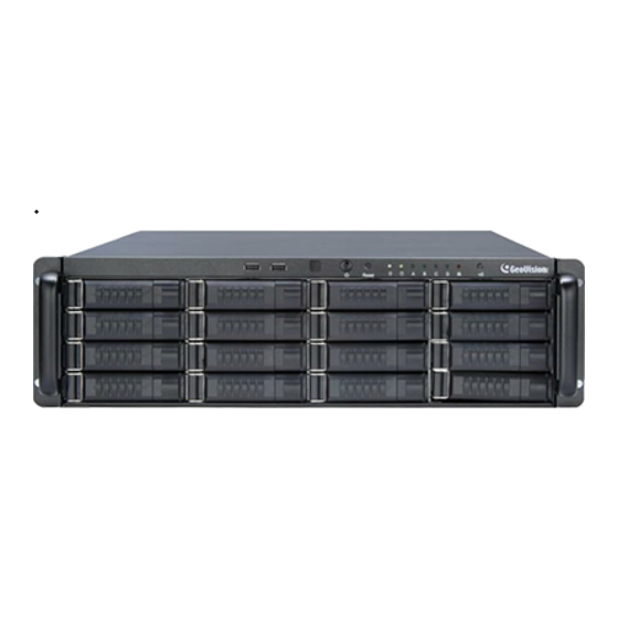
Page 16: 16 / 8-Bay) Models
Overview 2.1.2 3U (16 / 8-Bay) Models 2.1.2.1 16-Bay Models Figure 2-2 No. Name Name USB 3.1 Gen 1 Port x 2 HDD Group A Power Button HDD Group B Reset Button HDD Group C LED Panel HDD Group D (See 2.2 LED Panel View for details.)... -
Page 17: Led Panel View
2.2 LED Panel View A LED panel on the front door provides a quick indication of the activity status of hard disk drives. Note the panel design and function vary from model to model. 2.2.1 4U (20-Bay) / 3U (16-Bay) Models Figure 2-4 No. -
Page 18: 8-Bay) Models
Overview 2.2.2 3U (8-Bay) Models Figure 2-5 No. LED Description Power LED The LED shines when the power is on. HDD Activity LED The LED shines when the HDDs are writing or reading data. RAID Status 1 ~ 8 LEDs The LEDs of HDD 1 ~ 8 shine when the HDDs are powered. -
Page 19: Rear View
2.3 Rear View 2.3.1 4U (20-Bay) Models 2.3.1.1 GV-NVRH V5 / GV-VMSH V5 * 7 8 9 10 Figure 2-6 No. Name No. Name Gigabit Ethernet Port AC Power Switch AC Power Input (Full Range) RJ-11 Port I/O Terminal Block USB 2.0 Port x 2 Audio Line In Port USB 3.1 Gen 1 x 2... - Page 20 Overview 2.3.1.2 GV-Hot Swap Recording Server System Figure 2-7 For details on the other features of the motherboard and power supply on the rear panel, see Figure 2-6.
-
Page 21: 16-Bay) Models
2.3.2 3U (8 / 16-Bay) Models 2.3.1.1 GV-NVRH V5 / GV-VMSH V5 Figure 2-8 No. Name No. Name AC Power Input (Full Range) Gigabit Ethernet Port USB 2.0 Port x 2 RJ-11 Port USB 3.1 Gen 1 x 2 I/O Terminal Block HDMI Port Audio Line In Port USB Type C. - Page 22 Overview 2.3.2.2 GV-Hot Swap Recording Server System (Only 16-Bay Model) Figure 2-9 For details on the other features of the motherboard and power supply on the rear panel, see Figure 2-8. Note: There is no 3U (8-bay) model for GV-Hot Swap Recording Server System.
-
Page 23: Chapter 3 Getting Started
Chapter 3 Getting Started Basic Installation This section describes all the equipments required to program and operate the GV-Hot Swap Surveillance System V5. Up to 3 monitors can be connected to the System. 3.1.1 All Models Here we use the 4U (20-bay) models of GV-NVRH V5 as the example. Figure 3-1 1. - Page 24 Getting Started Connecting to 3 Monitors You can connect up to 3 monitors to the ports labeled below on the back panel of the GV-Hot Swap Surveillance System V5. Here we use the 3U (16-bay) model as the example. Figure 3-2...
-
Page 25: Turning On The Power
Turning on the Power Once the above hardware is properly connected, it is the time to turn on the GV-Hot Swap Surveillance System V5. To turn on the power, follow these steps: 1. Turn on the monitor. Power On Figure 3-3 2. - Page 26 2. For 4U (20-bay) and 3U (16-bay) models, the Power LED and the LEDs of HDD Groups A to D should shine after power is on. If any of HDD Group LEDs does not shine, please contact GeoVision.
-
Page 27: Installing The Hard Drive
Installing the Hard Drive The GV-Hot Swap Surveillance System V5 uses SATA hard drives for video and audio data storage. Before recording, be sure to install your hard drives. IMPORTANT: Be sure to install each of your hard drives separately for formatting. See 3.5 Formatting the Hard Drive for details. -
Page 28: Windows Setup Installation
Getting Started Windows Setup Installation The Windows setup is preparing your computer for first use. 1. After the Windows starts, this setup screen appears. Select your language and click Next to continue. Figure 3-8 2. Select your regional settings and time zone and click Next to continue. Figure 3-9... - Page 29 3. Click Accept to accept Microsoft software license terms. 4. Select between “Customize” or “Use Express settings” for your Windows 10 installation. 5. Type your account name. It is recommended that you create a password for your account and click Next . Figure 3-10 When the above setup process is complete, Windows will finalize your settings automatically in the background and restart.
-
Page 30: Formatting The Hard Drive
Getting Started Formatting the Hard Drive Be sure to install each of your hard drives separately for formatting. Do not install and format more than one hard drive at a time. Depending on the model of your choices, install and format the hard drives in alphabetical order as indicated below. - Page 31 To format a hard disk, follow the steps below: Right-click the Computer icon on your desktop, select Manage, and select Disk Management when the Computer Management window appears. 2. On the main page of Disk Management, the Initialize Disk dialog box appears for the new drive.
- Page 32 Getting Started The New Simple Volume Wizard appears. Click Next to continue. Figure 3-14 6. The default partition size is the same as the maximum disk space. Make changes if necessary. Click Next to continue. Figure 3-15...
- Page 33 7. Assign a drive path that is not in use by other devices, and click Next to continue. Figure 3-16 Note: The default drive path starts from D:\. 8. Type a name in the Volume label box, ex. HDD1, and click Next to continue. Figure 3-17...
- Page 34 Getting Started 9. When the formatting is complete, click Finish to close the wizard. Figure 3-18 10. When the drive is successfully initialized, partitioned, and formatted, its status description should display “Healthy.” Figure 3-19...
-
Page 35: Setting Up The Video Storage Location
Setting Up the Video Storage Location To achieve stable recording performance, you need to divide your hard disks into 4 / 8 storage groups and each group is assigned with an equal number of cameras. Note: Be sure to follow the hard drive installation of 20 / 16 / 8-bay models as below. See 3.5 Formatting the Hard Drive for details. - Page 36 Getting Started Storage Group 1 Storage Group 2 Storage Group 3 Storage Group 4 3U 16-bay GV-Hot Swap NVR / VMS System 64-channel Camera 01-16 Camera 17-32 Camera 33-48 Camera 49-64 Camera 01-08 Camera 09-16 Camera 17-24 Camera 25-32 32-channel 3U 8-bay Storage Group 1 Storage Group 2 Storage Group 3 Storage Group 4 GV-Hot Swap...
- Page 37 To create a storage group for GV-Hot Swap VMS System, 1. On the GV-VMS, open the Recording dialog box (Home > Toolbar > Configure > System Configure > Record Setting). 2. Select a camera and click next to Add Log Location to open the following dialog box. Figure 3-21 in the top-left corner.
- Page 38 Getting Started To create a storage group for GV-Hot Swap NVR System, On the GV-NVR, click the Set Location button and select Storage Group Folder. This dialog box appears. Figure 3-23 To create a storage group, click the Add Storage Group icon The first storage group is created by default.
- Page 39 To create a storage group for GV-Hot Swap Recording Server System, 1. On the GV-Recording Server, click Storage Path under Server. This dialog box appears. Figure 3-24 2. To create a storage group, click the Add button . The first storage group is created by default.
-
Page 40: Setting Up On-Screen Led Panel
Getting Started 3.7 Setting Up On-Screen LED Panel Note the function is not supported by GV-Hot Swap Recording Server System. For GV-Hot Swap NVR / VMS System, a LED panel on the screen provides a quick indication of the activity status of hard disk drives. Figure 3-25 LED Color Description... - Page 41 2. Click Tools on the menu bar and select Setup LED Panel. This dialog box appears. Figure 3-27 LED Panel always stays on top: This option makes the LED panel stay on top of other windows when the Media Man Tools window is minimized. Synchronize the LED Panel with the LED Device on GV-Hot Swap NVR: When ...
-
Page 42: Replacing The Hard Drive
Getting Started Replacing the Hard Drive You can replace the hard drive in the Hot Swap Drive Bay without shutting down the GV-Hot Swap Surveillance System V5. 1. Make sure the HDD Activity LED (No. 2, Figure 2-5) is off. 2. -
Page 43: Configuring The Ip Address
Configuring the IP Address The GV-Hot Swap Surveillance System V5 supports remote monitoring, control and configuration over a network connection. The following default IP addresses will automatically be assigned. 192.168.0.200 (All models) 192.168.0.201 (Only available for GV-Hot Swap NVR / VMS / Recording Server System) ... - Page 44 Getting Started To change the static IP addresses or to enable dynamic IP address, follow the steps below. 1. Right-click the Network Connection icon from the notification area and select Open Network and Sharing Center. Figure 3-29 2. Click Change Adapter Settings from the left-hand side menu of the Network and Sharing Centre window.
- Page 45 5. Select Use the following IP address and type the new IP information in the fields or select Obtain an IP address automatically to enable dynamic IP address. Figure 3-32 6. Click OK to finish the setting. Note: For models with multiple Ethernet ports, it is recommended to assign IP channels received and clients transmitted into different networks.
-
Page 46: Multi View Display
Getting Started 3.10 Multi View Display Note this function is not available for GV-Hot Swap Recording Server System. 3.10.1 GV-Hot Swap NVR System You can display multiple views on up to 6 monitors simultaneously, one for live viewing and the others for playback or other operation without obstructing surveillance scene, with GV-DVD / NVR System. - Page 47 8. Go to the system folder and locate DMPOS.exe. Figure 3-34 9. Run DMPOS.exe. This dialog box appears. Figure 3-35 10. In the Screen Setup tab, select a desired monitor display mode, such as Twin View or Three View, from the Displayer Mode drop-down list. 11.
-
Page 48: Gv-Hot Swap Vms System V5
Getting Started 3.10.2 GV-Hot Swap VMS System V5 You can customize the display settings of GV-VMS. Click Home , select Toolbar select Configure , select System Configure, and click Set Position. This dialog box appears. The right side of the dialog box is only available when multiple monitors are installed. Figure 3-36 ... -
Page 49: Digital Matrix
3.11 Digital Matrix Note this function is not available for GV-Hot Swap VMS System V5, GV-Hot Swap Recording Server System. To create more screen space to display multiple channels, such as 32 channels, Digital Matrix is thus introduced to provide a way to view and manage multiple monitor displays. The Digital Matrix includes these features: Live view: You can set different live views and screen divisions for each monitor. -
Page 50: Setting Live View
Getting Started 3.11.2 Setting Live View You can set different live views and screen divisions for each monitor. 1. On the main screen, click the Configure button, click Accessories, and select Digital Matrix Setting. This dialog box appears. Figure 3-38 2. -
Page 51: Setting Scanned
3.11.3 Setting Scanned Pages You can set up to 16 scanned pages with different screen divisions and channels for each monitor. 1. Use the Display list to select the monitor to be configured. 2. In the upper-left column, expand the Matrix folder tree, and then click Page 1. This page appears. -
Page 52: Setting Pop-Up Alert
Getting Started 3.11.4 Setting Pop-up Alert You can be alerted by pop-up live videos when motion is detected or I/O devices are triggered. 1. Use the Display list to select the monitor to be configured. 2. In the upper-left column, click Event Popup. This page appears. Figure 3-40 ... -
Page 53: Setting Pop-Up Positions
3.11.5 Setting Pop-up Positions When you select Random Position of Camera, you can decide the positions for pop-up cameras. Fixed Position of Camera: The cameras pop up in their assigned positions. To assign positions, select Screen Division. Then drag and drop the cameras number to the desired potions on the divisions. -
Page 54: Setting Live View With Pop-Up Alert
Getting Started 3.11.6 Setting Live View with Pop-up Alert You can set a different live view mode with pop-up alert together for each monitor. When alert events occur, the live video of the associated camera will pop up on the assigned monitor to replace its live view mode. -
Page 55: Extended Installation
3.12 Extended Installation Optionally, you can purchase GV-IR Remote Control or GV-Keyboard V3 accessories to make your unit even more powerful and convenient, Gigabit Network Cards for additional gigabit ports, and Redundant Power Supply for uninterrupted supply of power. GV-Keyboard V3 ... -
Page 56: Gv-Ir Remote Control
Getting Started After the System starts up, the Keyboard controller dialog box will automatically appear and start service. The dialog box will run in the background and closing the dialog box will cause GV-Keyboard V3 to disconnect. Figure 3-42 3.12.2 GV-IR Remote Control Note that this function is not supported by GV-Hot Swap Recording Server System. -
Page 57: I/O Devices
3.12.3 I/O Devices Note that this function is not supported by GV-Hot Swap Recording Server System. The GV-Hot Swap NVR / VMS System, with built-in GV-NET/IO Card, provides 4 alarm outputs and 4 sensor inputs. Relay Output 1~4 Com Sensor Input 1~4 Ground 4U (20-bay) &... -
Page 58: Gigabit Network Cards
Getting Started 3.12.4 Gigabit Network Cards The GV-Hot Swap Surveillance System V5 comes with a single onboard gigabit port. Only for GV-NVRH V5 / GV-VMSH V5, the System can support up to 3 gigabit ports with 1 optional Network Cards installed. The number of optional Network Cards supported varies with different models. -
Page 59: Redundant Power Supply
3.12.5 Redundant Power Supply The Redundant Power Supply comes with 2 modules for 3U models for 4U models. Each module shares the loading of the power supply. When one of the modules is down, the other module can still support full power for the GV-Hot Swap Surveillance System V5. 4U models Figure 3-45 3U models... - Page 60 Getting Started The LED Indicators 4U models Figure 3-47 LED Indicators Description Glow red on both modules when the power input is properly connected Ready LED to the power supply. Glow green on both modules when the Redundant Power Supply is Access LED functioning.
- Page 61 3U models Figure 3-48 LED Indicators Color Description Glows when the power input is properly connected to the Ready LED Orange power supply. Glows when the Redundant Power Supply is functioning. Access LED Green Glows when the Redundant Power Supply is not Alarm LED functioning properly, accompanying the audio alarm’s sound.
- Page 62 Getting Started The Audio Alarm When the audio alarm of the Redundant Power Supply rings, check: 1. if the modules are pushed all the way to the end, or 2. the power input is properly connected to the power supply. If the modules are properly installed but the audio alarm continues to ring, the module may be damaged and you may need to contact your distributor for a replacement.
-
Page 63: System Restoration
3.13 System Restoration You can restore preinstalled files once they are damaged by running the recovery from the hidden partition. To restore the operating system and all preinstalled software, follow the steps below. Note: After recovery, you need to re-install all settings and passwords. But the recovery will not delete your recording files saved on the GV-Hot Swap Surveillance System V5 since it only reformats the partition C and all of your files are still stored on other partitions. - Page 64 Getting Started 7. After selecting which partition you want to recover, click Start Restore and click Yes when the following message appears to start restoring. Figure 3-52 8. Once the restoration is complete, click Finish to leave the recovery system and restart the Windows automatically.
-
Page 65: Updating Gv-Hot Swap Surveillance System V5
3.14 Updating GV-Hot Swap Surveillance System V5 GeoVision will periodically update the GV-System Software (Multicam Surveillance System). If you like to update your GV-Hot Swap Surveillance System V5, contact your dealer for more information or check software update news at our website:... -
Page 66: Chapter 4A Troubleshooting
Troubleshooting Chapter 4 Troubleshooting GV-Hot Swap Surveillance System V5 is designed for durability. However, should problems occur, following the procedures here can help determine the cause. A portable 2.5'' HDD connected to the front panel cannot be detected. When the portable 2.5” HDD connected to a GV-Hot Swap Surveillance System V5 cannot be detected, try this step: Use a dual head USB cable and insert both heads to the USB ports on the GV-Hot Swap Surveillance System V5 front panel as illustrated below. - Page 67 GV-Hot Swap Surveillance System V5 won’t turn on. If your GV-Hot Swap Surveillance System V5 won’t turn on or you don't hear a startup sound or any fan or drive noise, try these steps: 1. For 4U (20-bay) models, make sure that you switch on the AC power on the rear panel. 4U (20-Bay) Models Figure 4-2 2.
- Page 68 Troubleshooting GV-Hot Swap Surveillance System V5’s hard disk corrupts. If you are experiencing file system corruption problems, such as lost clusters, cross-linked files or invalid files or directories, try these steps: 1. Use the HD Tune utility to scan the hard disk for errors. Follow these steps: A.
- Page 69 2. If the HD Tune utility does not find any defects, use the Windows built-in utility to attempt to fix the errors. Follow these steps: A. Right-click the Computer icon on your desktop, select Manage, and select Disk Management when the Computer Management window appears. B.
- Page 70 If your GV-Hot Swap Surveillance System V5 suffers virus attack, try rebuilding the operating system and the software. Refer to 3.13 System Restoration. How can I find more help? 1. Visit our website at http://www.geovision.com.tw/ 2. Write us at dvrsystem@geovision.com.tw...
-
Page 71: Specifications
Specifications GV-Hot Swap NVR / VMS System V5 (Rev. E) System Model 20-bay 16-bay 8-bay Intel Core i7 Processor 8 GB Dual Channels (NVRH V5); 16 GB Dual Channels (GV-VMSH V5) 64-bit Windows 10 IoT DirectX 20 (2.5” / 3.5" HDD) 16 (2.5”... - Page 72 Specifications Video and Audio (GV-NVRH V5) Model GV-NVR (GV) GV-NVR (3 Party) Video Input 32 channels 1, 2, 4, 6, 8, 10, 12, 16, 18, 20, 22, 24, 26, 28, 30, 32 channels Audio Input 32 channels 1, 2, 4, 6, 8, 10, 12, 16, 18, 20, 22, 24, 26, 28, 30, 32 channels Video Compression Geo MPEG4, Geo H.264 / H.265 Note: The H.265 CPU and GPU decoding are only supported by GV-NVR V8.7.0.0.
- Page 73 Alarm Standard 4 inputs Sensor Input GV-IO 12-In Card (Optional) 12 inputs GV-IO Box (Optional) 4, 8, 16 inputs Standard 4 outputs Alarm Output GV-IO 12-Out Card (Optional) 12 outputs GV-IO Box (Optional) 4, 8, 16 outputs Environment Operating Temp. 0 ~ 45 °C / 32 ~ 113 °F Humidity 0 ~ 80% RH (non-condensing)
- Page 74 Specifications Hard Disk Requirements The total of recording frame rates that you can assign to a single hard disk is listed as below: Frame Rate Limit in a Single Hard Disk H.264 H.265 Video Frame Rate Bitrate Frame Rate Bitrate resolution (fps) (Mbit/s)
- Page 75 Total Frame Rate and Max. No. of Channels Supported For GV-IP Camera (Dual Streams) GV-NVR V5 Video Dual-stream Resolution Max. Frame Total Frame Channel Resolution Rate / Camera Rate / System Stream 1 (H.264) Stream (H.264) 1.3 MP 1280 x 1024 320 x 256 30 fps 960 fps...
- Page 76 Specifications For GV-Fisheye Camera (Single Stream De-warping) GV-NVR V5 Video Single-Stream Resolution Max. Frame Rate / Total Frame Rate / Channel Resolution (H.264) Camera System 1.3 MP 1280 x 1200 15 fps 480 fps 2 MP 1440 x 1376 15 fps 480 fps 3 MP 2048 x 1536...
- Page 77 For Third-Party Camera (Single Stream GPU Decode) GV-NVR V5 Video Single-Stream Resolution Max. Frame Rate / Total Frame Rate / Channel Resolution (H.264) Camera System 1.3 MP 1260 x 1024 30 fps 960 fps 2 MP 1920 x 1080 30 fps 960 fps 3 MP 2048 x 1536...
- Page 78 Specifications GV-Hot Swap Recording Server System V5 (Rev. E) System Model 20-bay 16-bay Intel Core i7 Processor 16 GB Dual Channels 64-bit Windows 10 IoT DirectX 20 (2.5” / 3.5" HDD) 16 (2.5” / 3.5" HDD) No. of HDD 64 GB SSD 64 GB SSD Internal Storage RJ-45, 10 / 100 / 1000 Mbps x 3...
- Page 79 Software Specifications Number of IP Video 128 channels Device Connections Number of Remote Client 300 channels Connections Active Connections Passive Connections Yes (only for GV-IP Devices) 3rd Party IP Cameras Support Live Viewing Single live view, multi-channel live view Recording Yes (up to 128 channels) Protocol HTTP, HTTPS, TCP, UDP, SMTP, UPnP, DynDNS, RTSP, PSIA, ONVIF...
- Page 80 Specifications HDD Capacity The amount of time GV-Hot Swap Recording Server System can record before recycling begins is listed below. HDD capacity HDD Capacity for Amount of time each model Frame Resolution Bit rate required for each model can record before recycling rate recording 128ch begins...
-
Page 81: Appendix
Appendix A. Supported IP Devices This list provides the supported IP device brands. For detailed information on the supported IP devices, refer to Supported IP Camera List on GeoVision’s Website: http://www.geovision.com.tw/ GeoVision ACTi Arecont Vision AXIS Bosch Canon D-Link Etrovision... -
Page 82: Assigning Network Cards
Appendix B. Assigning Network Cards GV-NVRH V5 / GV-VMSH V5 and GV-Hot Swap Recording Server System come with multiple Ethernet ports. To increase network bandwidth and avoid network bottleneck, you need to set up multiple networks and divide networks into different multiple subnets or segments. Next, organize IP channels received and clients transmitted into different networks. - Page 83 For GV-VMSH V5, the recommended network allocation is illustrated as below. The first network card can receive up to 64 IP channels in 2 M resolution. The second network card can transmit up to 64 channels in 2 M resolution. For GV-Hot Swap Recording Server System, the recommended network allocation is illustrated as below.
-
Page 84: Combining Optional Accessories
Appendix C. Combining Optional Accessories The combination of options for GV-Hot Swap Surveillance System is listed below. Note: Redundant Power Supply can be combined with other GV-Hot Swap Surveillance System V5 (Rev. E) accessories for all models. You may choose an option if there is a Yes listed under the Network Cards columns. GV-NVRH V5 / GV-VMSH V5 has 2 gigabit ports by default and you can optionally add one more network card to have 3 gigabit ports in total. -
Page 85: Warranty Requirements
Warranty Requirements Thank you for purchasing the GV-Hot Swap Surveillance System V5. GeoVision understands that accidents happen, and have developed a warranty policy in place. See http://www.geovision.com.tw/warranty.php for more information on warranty. Before you return the product Some problems you experience may be related to software or the operating system. It is important to investigate other sources of assistance first. - Page 86 2. Securely pack the product in its original carton using the original packing material, or in equivalent packaging. 3. The product shall be returned to GeoVision, Taiwan at your expense for shipping and insurance costs. BEFORE YOU DELIVER YOUR GV-HOT SWAP SURVEILLANCE SYSTEM V5 FOR WARRANTY SERVICE, IT IS YOUR RESPONSIBILITY TO BACK UP YOUR DATA.
-
Page 87: Warranty Form
GeoVision Inc., 9F, No.246, Sec.1, Neihu Rd., Neihu District Taipei 114, Taiwan R.O.C. within 30 days from the date of purchase. Please keep this copy for your records. - Page 88 Warranty Form Bar Code: Shipment Date: GeoVision, Inc. 9F, No. 246, Sec. 1, Neihu Rd., Neihu District, Taipei, Taiwan Tel: +886-2-8797-8377 Fax: +886-2-8797-8335 Email: sales@geovision.com.tw dvrsystem@geovision.com.tw http://www.geovision.com.tw...
Need help?
Do you have a question about the GV-Hot Swap V5 Series and is the answer not in the manual?
Questions and answers