Table of Contents
Advertisement
Quick Links
Download this manual
See also:
User Manual
Advertisement
Table of Contents

Related Manuals for GeoVision GV-Data Capture V3


Summary of Contents for GeoVision GV-Data Capture V3
- Page 1 GV-Data Capture V3 Series User's Manual Before attempting to connect or operate this product, please read these instructions carefully and save this manual for future use. DCV31EV311-A-EN...
- Page 2 © 2013 GeoVision, Inc. All rights reserved. Under the copyright laws, this manual may not be copied, in whole or in part, without the written consent of GeoVision. Every effort has been made to ensure that the information in this manual is accurate.
- Page 3 Preface Welcome to the GV-Data Capture V3 Series User’s Manual. The GV-Data Capture V3 Series includes GV-Data Capture V3, GV-Data Capture V3E and GV-Data Capture V3.1E. This Manual is designed for the following models and firmware versions: Model Firmware Version GV-Data Capture V3 V1.0...
-
Page 4: Table Of Contents
Contents Preface..................i Naming and Definition ............iv 1. Getting Started ..............1 1.1 Introduction ....................1 1.2 Unpacking....................... 2 1.3 System Requirements..................2 2. Overview................3 2.1 DIP Switch Setup.................... 4 2.2 Baud Rate Setup..................... 5 3. V3 Settings ................6 3.1 Connections....................6 3.1.1 DB9 Serial Interface ..................... - Page 5 5. Specifications ..............29 6. Troubleshooting ..............30...
-
Page 6: Naming And Definition
Naming and Definition The GV-Data Capture V3 Series can work with both POS (Point of Sale) POS System systems and cash registers. In this manual, we use POS systems to cover the two types of applications. GeoVision Analog and Digital Video Recording Software. The GV-... -
Page 7: Getting Started
Getting Started 1. Getting Started This section describes the features of the GV-Data Capture V3 Series, the inventory of the items that have supplied with GV-Data Capture, and the software version required for this application. 1.1 Introduction The GV-Data Capture V3 Series can interface with POS systems and GV-System to overlay transaction data on video footage. -
Page 8: Unpacking
1.2 Unpacking • GV-Data Capture V3 / V3E box x 1 • DB9 RS-232 cable (1.8 meters) x 1 • DB9 RS-232 cable (3 meters) x 1 • DB25 RS-232 cable (1.8 meters) x 1 • Power Adaptor DC 5V x 1 •... -
Page 9: Overview
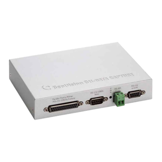
Overview 2. Overview This section identifies the various components of GV-Data Capture V3 Series. Front Panel Parallel Port to Printer RS-232 (DB9) RS-485 RS-232 /RS-232 (DB25) Female Male to DVR Rear Panel RS-232 (DB9) Parallel Port from POS DC IN... -
Page 10: Dip Switch Setup
2.1 DIP Switch Setup To adjust the DIP Switches, refer to the chart below. • If your POS system is parallel type, set DIP Switch SW1 to Down; otherwise keep the default setting. • If the output interface of your POS system is DB25, set DIP Switch SW2 to Up; otherwise keep the default setting. -
Page 11: Baud Rate Setup
Overview 2.2 Baud Rate Setup To have the POS data transferred to the GV-System via the GV-Data Capture, you need to set the exact baud rate in each connected device, including the GV-Data Capture and POS systems. On the side panel of the GV-Data Capture, there is a Baud Rate Switch. Each number (from 0 to 7) on the Switch represents a kind of baud rate. -
Page 12: V3 Settings
3. V3 Settings The GV-Data Capture V3 Series supports both serial and parallel types of POS systems. This section introduces how to connect the two types of POS systems to the GV-Data Capture, and how to configure the GV-System to receive the data from the POS system. -
Page 13: Db25 Serial Interface
3.1.2 DB25 Serial Interface The illustration below is an example of a POS system using an RJ45-DB25 cable. RJ-45 DB25 Female / Male POS System GV-System GeoVision GV-DATA CAPTURE V3 DB9 Female DB25 Male / Female DB9 Male RS-232 DB25... -
Page 14: Parallel Interface
GV-Data Capture (as illustrated below), or the GV-System will not be able to receive any transaction data. Parallel DB25 Male DB25 Female POS System GV-System GeoVision GV-DATA CAPTURE V3 DB9 Female DB25 Male DB9 Male RS-232 DB25 Female Parallel Terminator Printer •... -
Page 15: Extending Distance
V3 Settings 3.1.4 Extending Distance The previous three diagrams assume the physical distance between the POS system and GV-System is within 10 meters (32 ft). If the distance between the two devices is greater than 10 meters, it is required to use GV-NET series, GV-Hub or GV-COM in the connection. -
Page 16: Configuring Gv-System
3.2 Configuring GV-System Configure the GV-System to receive the transaction data from the POS system. 1. Click the Configure button on the main screen, point to POS Application Setting, and then select POS Device Setup. The POS Server Setup dialog box appears. 2. - Page 17 V3 Settings Data Bits: Select the number of data bits corresponding to that of the printer. Parity: Select None for the Serial POS system. Stop Bits: Select the stop bit corresponding to that of the printer. Cash Drawer Open Signal: This option is only available when an input module is configured in the GV-System.
-
Page 18: V3E Settings
4. V3E Settings The GV-Data Capture V3E is the Ethernet version of the GV-Data Capture V3. The V3E allows you to connect POS systems to the GV-System through LAN or Internet, overcoming the distance limit of RS-232 or RS-485 cables. -
Page 19: Fixed Ip
If your POS system supports a static IP address, the wiring is illustrated as below: POS System LAN or (Cash Register) INTERNET GV-Data Capture V3.1E GV-Data Capture V3E GV-System Printer Figure 8 Note: For connections among the POS system, printer and GV-Data Capture V3E, see 3.1 Connections. - Page 20 2. In the User Name and Password fields, type default value admin and 1234 respectively, and then click OK. This page appears. Figure 10 Note: User Name is fixed, but Password is changeable. See 4.3.3 Changing Password. 3. In the GV-Data Capture V3E Name field, name the connected V3E. 4.
-
Page 21: Dhcp
V3E Settings 4.1.2 DHCP If your POS system is using a dynamic IP address from a DHCP server, two types of DDNS servers are provided to tie a dynamic IP address to a static domain name or device name. This allows the GV-System to access your POS system by name. •... - Page 22 Installing LocalDDNS Server To install the LocalDDNS Server in a computer: 1. Insert the Surveillance System Software CD to your computer. It will run automatically and pop up a window. 2. Select Install GeoVision System. 3. Select GeoVision LocalDDNS Server, and then follow on-screen instructions. 4.
- Page 23 V3E Settings 3. Click Enable, and select Send to Local DDNS. 4. In Server IP field, type the IP address of the LocalDDNS server. 5. In Device Name field, keep the default setting or change it to match that of the GV- System (see Figure 20).
-
Page 24: Connection Over Internet
4.1.2.2 Connection over Internet DDNS (Dynamic Domain Name System) provides another way of accessing the POS system when using a dynamic IP. DDNS assigns a domain name to you POS system, so the GV-System can always access the POS system by the domain name. To enable the DDNS function, you should first apply for a domain name from the DDNS service provider’s website. - Page 25 V3E Settings Registering a DDNS Domain Name To obtain a domain name from the GeoVision DDNS Server: 1. In the left menu pane, click System Setting, and then click the GeoVision DDNS button (see Figure 10). Or open an Internet browser, and type the web address http://ns.dipmap.com/register.aspx.
- Page 26 5. Click the Send button. When the registration is complete, this page appears. Figure 16 For details, see “Using Dynamic DNS”, Chapter 13, GV-DVR User’s Manual on the Surveillance System Software CD. Note: The registered name will be invalid when it is not used for one month.
- Page 27 V3E Settings Configuring V3E for the Connection over Internet After registering a domain name on the DDNS Server, configure the V3E to meet your network requirements. 1. Follow the Steps 1 to 2 in 4.1.1 Fixed IP above. The GV-Data Capture V3E Web interface (see Figure 10) appears.
-
Page 28: Configuring Gv-System
4.2 Configuring GV-System After configuring the GV-Data Capture V3E, you need to set the GV-System to match your POS system’s network as well. 4.2.1 Fixed IP To set the GV-System for a static IP address network: 1. Click the Configure button on the main screen, point to POS Application Setting, and then select POS Device Setup. - Page 29 V3E Settings POS Module: Select the printer connected to the POS system. If it’s not Epson, select General for other brands. Cash Drawer Open Signal: This option is only available when an input module is configured in the GV-System. Assign the input module connected to the cash drawer.
-
Page 30: Dhcp
4.2.2 DHCP To set the GV-System for a dynamic IP address network, first decide your connection network is LAN or Internet. 4.2.2.1 Connection over LAN 1. Follow Steps 1 to 3 described in 4.2.1 Fixed IP. The Data Capture Box IP Setting dialog box appears. -
Page 31: Connection Over Internet
V3E Settings Setting button. The GV-Data Capture V3E Web interface (see Figure 10) will appear. 6. Click OK to add the POS system to GV-System. 4.2.2.2 Connection over Internet 1. Follow the Steps 1 to 3 in 4.2.1 Fixed IP. The Data Capture Box IP Setting dialog box appears. -
Page 32: Setup And Password
Baud Rate: Displays the baud rate set in the GV-Data Capture V3E. Data Bits: Select 7 bits or 8 bits for data transmission. Note this option is only available for GV-Data Capture V3.1E. Device Port: Keeps the default value 4000. Or modify it to match that of GV-System. -
Page 33: Updating Firmware
V3E Settings 4.3.2 Updating Firmware To update the firmware of the GV-Data Capture V3E: 1. In the left menu pane, click Firmware Update. This page appears. Figure 23 2. Click the Browse… button to open the firmware file (*.bin) 3. Click the Upload button. This update procedure may take 60 seconds to complete. 4. -
Page 34: Changing Password
4.3.3 Changing Password To change the login password: 1. In the left menu pane, click Password Setting. 2. On the Password Change page, type a password of 4 characters with the choices of “a ~ z” and “0 ~ 9”. Note that the password setting is case sensitive. Figure 25... -
Page 35: Specifications
Specifications 5. Specifications Specifications DB9 Female RS-232 from POS Input RS-232 from POS / DB25 Male / Parallel Port Parallel Port from POS DB9 Male RS-232 to Printer RS-232 to Printer / DB25 Female / Parallel Port Parallel Port to Printer DB9 Female RS-232 to DVR Output... -
Page 36: Troubleshooting
6. Troubleshooting Forgotten password or V3E’s IP address. Press the Reset button for 5 seconds. All the previous settings will be reset to defaults. Unable to configure when connecting more than one GV-Data Capture V3E to the same PC during first-time setup. 1. - Page 37 Troubleshooting 2. Check if the baud rates of the GV-Data Capture, POS system and GV-System are the same. For the baud rate setting in the GV-Data Capture, see 2.2 Baud Rate Setup. For the baud rate setting in the GV-System, see 3.2 Configuring GV-System. 3.
Need help?
Do you have a question about the GV-Data Capture V3 and is the answer not in the manual?
Questions and answers