
Related Manuals for AEMC Megohmmeters 6522


Summary of Contents for AEMC Megohmmeters 6522
- Page 1 99 Washington Street Melrose, MA 02176 Phone 781-665-1400 Toll Free 1-800-517-8431 Megohmmeters Visit us at www.TestEquipmentDepot.com Model 6522 & 6524 User Manual ENGLISH ® CHAUVIN ARNOUX GROUP...
-
Page 2: Statement Of Compliance
Statement of Compliance Chauvin Arnoux , Inc. d.b.a. AEMC Instruments ® ® certifies that this instrument has been calibrated using standards and instruments traceable to international standards. We guarantee that at the time of shipping your instrument has met its published specifications. - Page 3 Chauvin Arnoux , Inc and AEMC are registered trademarks of AEMC Instruments. ® ®...
- Page 4 Thank you for purchasing the Megohmmeter Model 6522 or 6524. For best results from your instrument: ■ Read these operating instructions carefully ■ Comply with the precautions for use WARNING, risk of DANGER! The operator must refer to these instructions whenever this danger symbol appears WARNING, risk of electric shock.
- Page 5 PRECAUTIONS FOR USE This instrument is compliant with safety standard IEC 61010-2-030, and the leads are compliant with IEC 61010-031, for voltages up to 600V in CAT IV or 1000V in CAT III. Failure to observe the following safety instructions may result in electric shock, fire, explosion, and damage to the instrument and installation.
-
Page 6: Table Of Contents
Table of Contents 1. INTRODUCTION ..............4 1.1 Receiving Your Shipment..............4 1.2 Accessories...................5 1.3 Replacement Parts ................5 1.4 Description ....................5 1.4.1 Model 6522 (Front) ..............6 1.4.2 Model 6524 (Front) ..............7 1.5 Back of Instrument ................8 1.6 Terminals ....................9 1.7 Function Buttons ...................9 1.8 LCD Display ..................10 2. - Page 7 2.3.3 Deleting Recordings ...............28 2.3.3.1 Deleting a Single Recording ..........28 2.3.3.2 Deleting All Recordings ..........28 3. SPECIFICATIONS ..............29 3.1 General Reference Conditions ............29 3.2 Electrical Specifications ..............29 3.2.1 Voltage Measurement.............29 3.2.2 Frequency Measurement............30 3.2.3 Insulation Measurement ............30 3.2.4 Continuity Measurement............32 3.2.5 Resistance Measurement (Model 6524).........32 3.2.6 Timer..................32 3.2.7 Storage Memory (Model 6524) ..........33...
-
Page 8: Introduction
1. INTRODUCTION 1.1 Receiving Your Shipment Upon receiving your megohmmeter product package, ensure the contents are consistent with the packing list. Notify your distributor of any missing items. If the equipment appears to be damaged, file a claim immediately with the carrier and notify your distributor at once, providing a detailed description. -
Page 9: Accessories
1.2 Accessories Megohmmeter Test Probe ..............Cat. #2155.75 Case - Field Case (Waterproof) ............Cat. #2118.98 Case - Hands Free Carrying Case ........... Cat. #2118.99 Continuity Pole .................Cat. #2138.54 Probe - Set of 2, Color-coded (Red/Black) Grip Probes ....Cat. #2152.26 1.3 Replacement Parts Lead - Set of 2, Color-coded 5 ft (Red/Black) Silicone Leads, Test Probes &... -
Page 10: Model 6522 (Front)
1.4.1 Model 6522 (Front) M mAµA < ALARM HOLD TEST Ω 250V Ω 500V 1000V MEGOHMMETER MODEL 6522 Figure 1 Input terminals Blue backlit LCD Four function buttons (see § 1.7) TEST button to start insulation measurements (see § 2.2.2.1) Six-position rotary switch to choose the function or to turn the instrument Megohmmeter Model 6522/6524... -
Page 11: Model 6524 (Front)
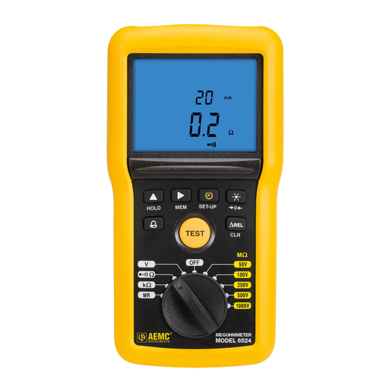
1.4.2 Model 6524 (Front) DARPI T1T2 G VHz % M mAµA < > ALARM HOLD TEST Ω Ω 100V Ω 250V 500V 1000V MEGOHMMETER MODEL 6524 Figure 2 Input terminals Blue backlit LCD Six function buttons (see § 1.7) TEST button to start insulation measurements (see § 2.2.2.1) Ten-position rotary switch to choose the function or to turn the instrument Megohmmeter Model 6522/6524... -
Page 12: Back Of Instrument
1.5 Back of Instrument Figure 3 Captive quarter-turn screw Battery compartment cover Mounting magnets, molded into instrument case (Model 6524) Non-skid pads Stand... -
Page 13: Terminals
1.6 Terminals > 700V 600V CAT IV Figure 4 The instrument has one positive ( + ) terminal and one negative ( - ) terminal. The negative terminal also supports the remote probe accessory (see § 2.2.2.3). 1.7 Function Buttons In general, each button has two functions. -
Page 14: Lcd Display
1.8 LCD Display DARPI T1T2 G VHz % M mAµA < > ALARM k nF/ km G nF µF HOLD Figure 5 1. Logarithmic bar graph displays insulation measurements 2. Secondary display area 3. Main display area 4. Icons/indicators When the measured value is below the minimum, the instrument displays - - - - . When measuring voltage, if the reading falls outside the range defined by the positive and negative limits, the instrument displays OL or –... -
Page 15: Operation
2. OPERATION Except when measuring voltage, all measurements must be made on powered- off systems. Therefore check to ensure there is no voltage on the system under test before making a non-voltage measurement. When the rotary switch is set to the voltage or an insulation testing position, the instrument measures and displays any voltage present at the input terminals prior to the user pressing the test button. -
Page 16: Alarms
press Automatic switching to standby on mode is activated. To deactivate it: 1. Press to select OFF (the setting blinks). 2. Press to change the setting to On. 3. Press to validate the change. symbol appears on the display when you exit Set-Up. -
Page 17: Setting An Alarm Threshold
Model 6524: The alarm is available in insulation, resistance, and continuity measurement modes. Pressing the button activates the alarm. The symbol is displayed, along with the threshold value. < ALARM To turn OFF the alarm buzzer while it is sounding, press the HOLD button. To deactivate an active alarm function, press the button. -
Page 18: Viewing Alarms
In each measurement mode, the third threshold can be replaced by a user- defined value. To do this: 1. Press the ► button while the threshold value is displayed. 2. The > symbol starts blinking; you can change it to < by pressing the button. -
Page 19: Rel Function (Model 6524)
2.1.3 ∆REL Function (Model 6524) For an insulation, resistance, or capacitance measurement, you can configure the instrument to subtract a reference value from the measured value and display the difference. To activate this function, take a measurement, and then press the ∆REL button. -
Page 20: Hold Function
2.1.4 HOLD Function Pressing the HOLD button freezes the display of the measurement. This can be done in all functions except the MΩ , DAR, PI). settings, or during a timed measurement ( To unfreeze the display, press the HOLD button again. 2.1.5 Backlighting ... -
Page 21: Taking Measurements
2.2 Taking Measurements 2.2.1 Voltage Measurement To ensure proper and accurate operation of the instrument, we recommend measuring a known voltage (such as an electrical outlet) before measuring unknown voltages. 1. Set the switch to V or to one of the MΩ positions. Ω... -
Page 22: Insulation Measurement
In the MΩ settings, the symbol indicates that the voltage is too high (>25V) and that insulation measurements are prohibited: If the voltage is >15V, continuity, resistance, and capacitance measurements are prohibited. 2.2.2 Insulation Measurement Insulation measurement results can be affected by the impedances of additional circuits connected in parallel or by transient currents. - Page 23 Ω Ω 100V Ω 250V 500V 1000V 2. Use the leads to connect the system to be tested to the instrument’s terminals. The system under test must be powered down and discharged. When testing insulation, the typical connection is negative (black) lead to conductor and positive (red) lead to ground or the outer insulation of the device under test.
-
Page 24: Test Button Operation
> 1s TEST symbol indicates that the instrument is generating a hazardous voltage (>70V). 6. At the end of the measurement, release the TEST button. The instrument stops generating the test voltage and discharges the device being tested. The symbol is displayed until the voltage on the system under test has fallen below 70V. -
Page 25: Timed Tests
2.2.2.2 Timed Tests The TIMER button activates timed test mode. This button is active only for insulation measurements. press This locks the TEST button. After you start the measurement, it continues to run without requir- ing you to keep the TEST button pressed. The test will run until you stop it, or when 15 minutes have passed. -
Page 26: Remote Control Probe (Optional)
Successive presses on the button display intermediate values. These include: ■ Programmed time, voltage, and current at the end of the measurement For PI and DAR: ■ T1 time and the voltage, current, and insulation resistance at that time ■... -
Page 27: Continuity Measurement
When the probe is connected, the symbol is displayed on the instrument’s LCD. NOTE: The remote probe can also be used as a passive probe by simply touching the probe tip to the test point. It is not necessary to press the test button. -
Page 28: Continuity Measuring
The display changes to zero and the symbol is displayed. The resistance of the leads will be systematically subtracted from all continuity measurements. If the resistance of the leads is >10Ω, there is no compensation. The compensation remains in memory until the instrument is turned OFF. If the leads are changed with no change of compensation, the display may become negative. -
Page 29: Resistance Measurement (Model 6524)
The instrument displays the resistance and the current used in the test. To obtain a continuity value per standard IEC 61557: 1. Take a measurement at 200 mA and note its value, 2. Reverse the leads and note the value R2. 3. -
Page 30: Recording Data (Model 6524)
2. Connect the system to be tested to the instrument. The device to be tested must be powered down. 3. The instrument displays the results. 2.3 Recording Data (Model 6524) 2.3.1 Recording a Measurement A measurement can be stored in the instrument’s memory if the measurement is: ■... -
Page 31: Viewing Stored Recordings
2.3.2 Viewing Stored Recordings 1. Set the rotary switch to MR. Ω Ω 100V Ω 250V 500V 1000V 2. The instrument displays the last recording stored in the instrument. The secondary (top) display indicates the memory location; while the main display indicates the measured value. -
Page 32: Deleting Recordings
2.3.3 Deleting Recordings 2.3.3.1 Deleting a Single Recording 1. Set the rotary switch to MR. 2. Use the and buttons to select the number of the recording to be deleted. 3. Press the CLR button for >2 seconds. The record number blinks and the LCD displays the letters CLR. -
Page 33: Specifications
3. SPECIFICATIONS 3.1 General Reference Conditions Quantity of Influence Reference Values Temperature 23° ± 3°C (73.4° ± 5.4°F) Relative humidity 45 to 55% RH Frequency DC and 45 to 65Hz 8 ± 0.2V Supply voltage battery life indication 58% ± 8% Electric field 0V/m Magnetic field... -
Page 34: Frequency Measurement
3.2.2 Frequency Measurement Measurement Range 15.3 to 399.9V 400 to 700V Resolution 0.1Hz Intrinsic uncertainty ± (1% R + 2 ct) ± (1.5% R + 1 ct) 3.2.3 Insulation Measurement Specific reference condition: Capacitance in parallel on resistance = null Measurement Ranges per Model Test Voltage Model 6522... - Page 35 Test Voltage Measurement 0.0 to 399.9V 400 to 1250V Range Resolution 0.1V Accuracy ± (3% R + 3 ct) Typical Discharge Time after Test To go from V to 25V, the discharge time is < 2s/µF. Test Current Maximum test current: 2mA Measurement 0.01 to 40.0 to...
-
Page 36: Continuity Measurement
3.2.4 Continuity Measurement Specific reference condition: Inductance in series with the resistance = zero. Measurement Range (without 0.00* to 10.00Ω 0.0 * to 100.0Ω compensation of the leads) Resolution 10mΩ 100mΩ Accuracy ± (2% + 2 ct) Test Current 200mA 20mA Open Voltage ≥... -
Page 37: Storage Memory (Model 6524)
3.2.7 Storage Memory (Model 6524) Maximum number of recordings stored in memory: 300 3.3 Operating Environment 3.3.1 Voltage Measurement Influence Influencing Range of Quantity Parameter influence influenced Typical Maximum 0.3% R/10°C 20 to + 55°C + 1 ct Temperature V, F (-4 to 131°F) (0.3% R/18°F + 1 ct) -
Page 38: Insulation Measurement
3.3.2 Insulation Measurement Influence Influencing Range of Quantity Parameter Influence Influenced Typical Maximum 2% R/10°C + MΩ 2 ct R ≤ 3GΩ 1% R/10°C 3% R/10°C + 3GΩ < R < 10GΩ + 1pt 2 ct 10GΩ ≤ R 4% R/10°C + 2 ct -20 to + 55°C Temperature... -
Page 39: Resistance And Continuity Measurement
Common mode 0 to 600V 50dB 40dB rejection in AC 50/60 Hz 3.3.3 Resistance and Continuity Measurement Influence Influencing Range of Quantity parameter influence influenced Typical Maximum 2% R/10°C + at 200mA 2 ct -20 to + 55°C 2% R/10°C + Temperature at 20mA (-4 to 131°F) -
Page 40: Intrinsic Uncertainty And Operating Uncertainty
3.3.4 Intrinsic Uncertainty and Operating Uncertainty These megohmmeters comply with standard IEC 61557, which requires that the operating uncertainty (called B) must be less than 30%. In insulation and continuity measurements: where: A = intrinsic uncertainty = influence of the reference position ± 90° = influence of the supply voltage within the limits indicated by the manufacturer = influence of the temperature between 0 and 35°C (32 and 95°F) -
Page 41: Mechanical Specifications
3.6 Mechanical Specifications Dimensions (L x W x H): 211 x 108 x 60mm (8.31 x 4.25 x 2.36”) Weight: approximately 850g (1.87lb) Ingress protection: ■ IP 54 per IEC 60529, not in operation ■ IK 04 per IEC 50102 Drop test: per IEC 610 3.7 Safety Standards Safety according to: EN 61010-2-30 : 2010... -
Page 42: Maintenance & Troubleshooting
4. MAINTENANCE & TROUBLESHOOTING Except for the batteries, the instrument contains no parts that can be replaced by personnel who have not been specially trained and accredited. Any unauthorized repair or replacement of a part by an “equivalent” may impair safety. 4.1 Maintenance 4.1.1 Cleaning Disconnect the unit completely and turn the rotary switch to OFF. - Page 43 This indicates the batteries must be replaced. All batteries must be replaced at the same time. To do this: 1. Disconnect any attached leads or accessories from the instrument and turn the rotary switch to OFF. 2. Use a tool or a coin to turn the quarter-turn screw of the battery compartment cover.
-
Page 44: Troubleshooting
5. Place the new batteries in the compartment, ensuring that each battery’s polarity is correct. 6. Put the battery compartment cover in place and screw the quarter-turn screw back in. 4.2 Troubleshooting 4.2.1 Errors During instrument operation, errors may be displayed on the LCD. The causes of any errors must be corrected before the instrument can resume normal operation. -
Page 45: Voltage During Continuity/Resistance/Measurement
With the Model 6524, if this condition occurs during a DAR or PI measurement, the instrument interrupts the measurement and displays the screen shown to the left. 4.2.1.3 Voltage present during a continuity, resistance, or capacitance measurement If during a continuity, resistance, or capacitance measurement the instrument detects an external voltage in excess of 15V (AC or DC),... -
Page 46: Repair And Calibration
Instruments will do: If a malfunction occurs within the one- ® year period, you may return the instrument to us for repair, provided we have your warranty registration information on file or a proof of purchase. AEMC ® Instruments will, at its option, repair or replace the faulty material. - Page 47 ® CHAUVIN ARNOUX GROUP 04/16 99-MAN 100429 v1 Test Equipment Depot - 800.517.8431 - 99 Washington Street Melrose, MA 02176 TestEquipmentDepot.com...
Need help?
Do you have a question about the Megohmmeters 6522 and is the answer not in the manual?
Questions and answers