
Related Manuals for AEMC 1030


Summary of Contents for AEMC 1030
- Page 1 1030 DIGITAL / ANALOG MEGOHMMETERS 1040 1045 E N G L I S H User Manual 0.561.8187 information@itm. www. .com...
-
Page 2: Statement Of Compliance
12 months and begins on the date of receipt by the customer. For recalibration, please use our calibration services. Refer to our repair and calibration section at www.aemc.com. Serial #: ________________________________ Catalog #: 2116.89/2116.92 / 2116.93 Model #:... -
Page 3: Table Of Contents
1.3 Receiving Your Shipment ...............4 1.4 Ordering Information ..............5 1.4.1 Accessories and Replacement Parts ........5 2. PRODUCT FEATURES ............... 6 2.1 Description ..................6 2.2 Control Features ................7 2.2.1 Model 1030 ................7 2.2.2 Model 1040 ................8 2.2.3 Model 1045 ................9 2.3 Display Features ................10 2.3.1 LCD Display Symbols ............10 2.3.2 Analog Bargraph .............10 2.3.3 Digital Display Symbols ...........10... - Page 4 2.6.6 Measurement Lead Resistance Compensation (Models 1040/1045) ............18 (Model 1045) .............19 2.6.7 Timer 3. SPECIFICATIONS ..............20 3.1 Electrical Specifications ...............20 3.1.1 Reference Conditions ............20 3.1.2 Voltage Detection ............20 3.1.3 Insulation Resistance Testing ..........20 3.1.4 Continuity ................21 3.1.5 Resistance (Model 1040/1045) ..........21 3.1.6 Timer (Model 1045) ..............22 3.1.7 Power Supply ..............22 3.2 Environmental Specifications ............22 3.2.1 Influencing Parameters ...........22 3.2.2 Limits ................23...
-
Page 5: Introduction
CHAPTER 1 INTRODUCTION Warning These safety warnings are provided to ensure the safety of personnel and proper operation of the instrument. • Read the instruction manual completely and follow all safety information before operating this instrument. • Safety is the responsibility of the operator! • Tests are to be carried out only on non-energized circuits! Check for live circuits before making resistance measure- ments (safety check). • The Megohmmeter Models 1030, 1040 and 1045 are sources of high voltage, as is the sample connected to them. All persons performing or assisting in the tests must employ all safety precautions to prevent electrical shock to themselves and to others. • AEMC considers the use of rubber gloves to be an ® excellent safety practice even if the equipment is properly operated and correctly grounded. • When testing capacitance samples, make sure that they have been properly discharged and that they are safe to touch. Dielectric insulation samples should be short- circuited for at least five times the amount of time they were energized. • Megohmmeters should never be used in an explosive envi- ronment. • Use the leads supplied with the megohmmeters. If they are defective or worn, replace before testing. • This instrument can be used on installations rated for 300V, Category II (CAT II). -
Page 6: International Electrical Symbols
CAT IV: For measurements performed at the primary electrical supply (<1000V) such as on primary overcurrent protection devices, ripple control units, or meters. Receiving Your Shipment Upon receiving your shipment, make sure that the contents are consistent with the ordering information. Notify your distributor of any missing items. If the equipment appears to be damaged, file a claim immediately with the carrier and notify your distributor at once, giving a detailed description of any damage. Save the damaged packing container to substantiate your claim. Do not use an instrument that appears to be damaged. Megohmmeter Models 1030/1040/1045 0.561.8187 information@itm. www. .com... -
Page 7: Ordering Information
Soft Carrying Pouch ............Cat. #2119.02 Set of 5 Fuses, Fast Acting, 600V, 0.63A 1/4 x 1 1/4" (6.3 x 32mm) .......... Cat. #2970.78 Field Case (Waterproof) ............Cat. #2118.98 Hands Free Carrying Case ..........Cat. #2118.99 Replacement Lead Set (2 leads, probe, 2 alligator clips).......... Cat. #2119.01 Order Accessories and Replacement Parts Directly Online Check our Storefront at www.aemc.com/store for availability Megohmmeter Models 1030/1040/1045 0.561.8187 information@itm. www. .com... -
Page 8: Product Features
They are designed to measure insulation resistance, continuity, voltage, and to measure resistance. These megohmmeters are used to verify the safety state of electrical installations, motors, cables and other insulated products. The measure- ment acquisition, processing and displaying technology are managed by a microprocessor. The Models 1030, 1040 and 1045 offer many features such as: • Automatic detection of potentially dangerous voltages • Protection against external voltage surges • Enhanced operator safety through automatic discharge of the tested sample • Automatic shutdown to optimize the battery life • Large LCD display with easy to read symbols and indicators and,... -
Page 9: Control Features
Control Features 2.2.1 Model 1030 20Ω MΩ - 500V MΩ - 250V MEGOHMMETER ® MODEL 1030 I N S T R U M E N T S Figure 1 1. Safety terminals, Ø 4mm (marked “+” on Red and “-”) 2. Liquid crystal display (LCD) 3. Yellow test button (used to test insulation resistance) 4. 4 position rotary switch: OFF, MΩ - 250V, MΩ - 500V, 20Ω... -
Page 10: Model 1040
20Ω MEGOHMMETER ® MODEL 1040 I N S T R U M E N T S Figure 2 1. Safety terminals, Ø 4mm (marked “+” on Red and “-”). Note the input for the remote test probe (3-point jack) next to the “-” terminal. 2. Backlight liquid crystal display (LCD) with primary (large) display and secondary (small) display for alarm and timer features. 3. Yellow test button (to test insulation resistance), ALARM, selection and scroll cursors , , and backlight buttons. 4. 5 position rotary switch: OFF, MΩ - 500V, MΩ - 1000V, 400kΩ, 20Ω 5. Battery compartment and stand (stand not shown in the drawing). Megohmmeter Models 1030/1040/1045 0.561.8187 information@itm. www. .com... -
Page 11: Model 1045
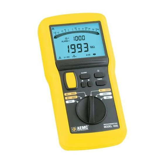
20Ω MEGOHMMETER ® MODEL 1045 I N S T R U M E N T S Figure 3 1. Safety terminals, Ø 4mm (marked “+” on Red and “-”). Note the input for the remote test probe (3-point jack) next to the “-” terminal 2. Backlight liquid crystal display (LCD) with primary (large) display and secondary (small) display for alarm and timer features 3. Yellow test button (to test insulation resistance), ALARM, selection and scroll cursors , , and backlight buttons 4. 6 position rotary switch: OFF, MΩ - 250V, MΩ - 500V, MΩ - 1000V, 400kΩ, 20Ω 5. Battery compartment and stand (stand not shown in the drawing) Megohmmeter Models 1030/1040/1045 0.561.8187 information@itm. www. .com... -
Page 12: Display Features
< Alarm triggered below setpoint Dangerous test voltage generated See the user manual > 25V Voltage at terminals (non generated) > 25V Ω Compensated lead resistance Buzzer active Auto Off disabled (no automatic shutdown) Battery status Ω Flashing: incorrect compensation of lead resistance 2.3.2 Analog Bargraph Insulation > 2GΩ Insulation < 50kΩ 2.3.3 Digital Display Symbols BAT Batteries low – must be replaced Over Range - Over Load - - - Insulation < 50kΩ at 250V, < 100kΩ at 500V or < 200kΩ at 1000V Megohmmeter Models 1030/1040/1045 0.561.8187 information@itm. www. .com... -
Page 13: Control Features
2.4.2 ALARM Button (Models 1040/1045) The ALARM button is used to turn the alarm ON and OFF for insulation, resistance, and continuity measurements. It is also used with the and selection cursor buttons to adjust the alarm set points. 2.4.3 Cursor Button (Models 1040/1045) When programming the alarm setpoints, the cursor button makes the following symbols flash as follows: • the measurement unit (if applicable), • the thousands digit, • the hundreds digit, • the tens digit, • the units digit, • the decimal point, • the alarm trigger (above or below the setting), • and it then returns to the measurement units. Megohmmeter Models 1030/1040/1045 0.561.8187 information@itm. www. .com... -
Page 14: Scroll Cursor Button (Models 1040/1045)
2.5.1 Insulation Resistance Testing The rotary switch MΩ positions determine the insulation resistance testing voltage. Tests are to be carried out on non-energized circuits only! • Voltage Detection (Safety Check) This is an automatic safety feature. As soon as the switch is turned to a MΩ position and before the yellow test button is pressed, the megohmmeter enters a voltage detection mode. It measures any voltage between the test leads and the sample. This is a safety check to ensure that the tested sample is not live. Megohmmeter Models 1030/1040/1045 0.561.8187 information@itm. www. .com... - Page 15 (safety check). It may continue to display the voltage, due to the possibly charged sample. The voltage may drop off more or less rapidly based on the sample capacitance. Megohmmeter Models 1030/1040/1045 0.561.8187 information@itm. www.
-
Page 16: Continuity Testing
Note (Models 1040/1045): The resistance of the measurement leads may be compensated. The alarm may be active in the continuity mode (see §2.6.5). Note (Model 1030): In the continuity mode, a lower alarm point of 2Ω is constantly active. The buzzer will sound below this value. However, the buzzer may be disabled by pressing the yellow button. 2.5.3 Resistance Measurement (Models 1040/1045) Measurements to be carried out on non-energized circuits only! Resistance measurement corresponds to the 400kΩ position of the rotary... -
Page 17: Special Functions
(which means that a measurement is in progress). On the Model 1045, in the TIMER mode (see §2.6.7), the five minutes steady state begins at the end of the maximum 15-minute measurement period. • Disabling/Enabling the Auto OFF (Models 1040/1045) To disable the Auto OFF, keep the button pressed down when turning ON the instrument. The symbol is then displayed, indicating that the Auto OFF function has been disabled. To enable the Auto OFF function, turn the instrument off (turn the switch to OFF) and then turn it back on again. Auto OFF is the default mode. Megohmmeter Models 1030/1040/1045 0.561.8187 information@itm. www. .com... -
Page 18: Battery Auto Test
2.6.4 Buzzer • The Different Sounds When the symbol is displayed, the buzzer is active and gives out differ- ent sounds, depending on the operation or warning. • Short buzz (65 ms at 2kHz): - push on a button - auto OFF - lead resistance compensation - after 30 s, 1 min and 10 min during TIMED insulation resis- tance measurement (Model 1045) • Continuous buzz (at 2kHz): - measurement is lower than the minimum setpoint - measurement is higher than the maximum setpoint • Short, higher buzz (65 ms at 4kHz): - when a disabled (inactive) button is pressed (except the yellow test button) • Repeated high buzzes (at 4kHz): - the detected voltage (safety check) at the sample is greater than 25V, and the user presses the yellow test button Megohmmeter Models 1030/1040/1045 0.561.8187 information@itm. www. .com... -
Page 19: Alarm Setpoints (Models 1040/1045)
• Disabling/Enabling the Buzzer Model 1030: to disable the buzzer, turn the rotary switch to continuity measurement (20Ω), and then press the yellow test button. The buzzer sounds and the buzzer symbol turns off. To enable the buzzer, press the yellow test button again, or turn switch to OFF and then back on again. Buzzer on is the default mode. Models 1040 and Model 1045: to disable the buzzer, keep the ALARM button pressed down and turn the instrument ON. The buzzer symbol is off (not lit). To enable the buzzer, turn switch to OFF and then back on again. Buzzer on is the default mode. 2.6.5 Alarm Setpoints (Models 1040/1045) Alarm setpoints are fully programmable for each function. There can be... -
Page 20: (Models 1040/1045)
To compensate (offset) the test leads resistance, short-circuit the leads and press the button for a short time (long press). When the compensa- tion has been recorded, the display indicates 0.00 and the buzzer sounds. From this moment on, the measurements displayed will be automatically Ω reduced by the value recorded and the symbol will de displayed. To delete the compensated lead resistance, remove the test leads and press the button for a short time (long press). When the lead compen- Ω sation is cancelled, the symbol goes out. Note that the maximum 20Ω continuity measurement range is reduced by the stored compensation value. Megohmmeter Models 1030/1040/1045 0.561.8187 information@itm. www. .com... -
Page 21: Timer (Model 1045)
When measuring, if an alarm setpoint is triggered, the buzzer sounds and display of the timer is interrupted to display the alarm message (see §2.6.5). If you forget to stop the insulation test in the TIMER mode, the megohmmeter will automatically switch back to voltage measurement after 15 minutes and the TIMER remains locked at 15:00. Megohmmeter Models 1030/1040/1045 0.561.8187 information@itm. www. .com... -
Page 22: Specifications
Magnetic field < 40A/m 3.1.2 Voltage Detection Detection Range: 0 to 600V AC/DC 3.1.3 Insulation Resistance Testing Measurement Range: Model 1030: 250V 50kΩ to 2GΩ 500V 100kΩ to 2GΩ Model 1040: 500V 100kΩ to 2GΩ 1000V 200kΩ to 2GΩ Model 1045: 250V 50kΩ to 2GΩ... -
Page 23: Continuity
3.1.5 Resistance (Model 1040/1045) Measurement Range: 0 to 400kΩ Range 0.0 to 399.9Ω 400 to 3999Ω 4.00 to 39.99kΩ 40.0 to 399.9kΩ Resolution 0.1Ω 1Ω 10Ω 100Ω Accuracy 3% Rdg ± 5cts 3% Rdg ± 1ct Test Current 600µA 60µA Open Circuit 7V ≤ V open ≤ 9V Voltage Megohmmeter Models 1030/1040/1045 0.561.8187 information@itm. www. .com... -
Page 24: Timer (Model 1045)
Environmental Specifications Storage without battery Reference Temperature in °C Indoor use, altitude up to 2000m, temperature 0 to 40°C, maximum relative humidity 80% for temperatures up to 31°C, decreasing linearly to 50% relative humidity at 40°C. Megohmmeter Models 1030/1040/1045 0.561.8187 information@itm. www. .com... -
Page 25: Influencing Parameters
The megohmmeters are protected on all ranges against a voltage of 720V , applied permanently between any two terminals. AC/DC The Models 1040 and 1045 are also protected against accidental voltage surges of 1200V on all ranges for 10s. AC/DC Mechanical Specifications LCD Display: 2.87 x 2.14" (73 x 54.3mm) Dimensions: 8.30 x 4.25 x 2.36" (211 x 108 x 60mm) Weight: Approx 830g Materials: Polycarbonate casing Crystal polycarbonate screen Elastomer external mouldings Silicon keyboard Stand: Enables the instrument to be tilted at 30°. Clips away into the bottom of the case when not in use. Safety Specifications Electrical Safety (according to IEC 1010-1 +A2 (Nov. '95), IEC 61557 (Feb. '97), and DIN EN 61557) 300Vrms, Cat. II, Pollution Degree 2 Electromagnetic Compatibility: Emissivity: NF EN 55 081-1 (June ‘92) Immunity: NF EN 55 082-1 (Jan. ‘98) IP44 according to NF EN 60529 (Oct. ‘92) IK04 according to NF EN 50102 (June ‘95) UL Listed: E192383 Megohmmeter Models 1030/1040/1045 0.561.8187 information@itm. www. .com... -
Page 26: Application Examples
APPLICATION EXAMPLES 3.5.1 Insulation Measurements on Installations Ω ALARM Ω Ω Ω Ω Ω ALARM Ω Ω Ω Ω Figure 4 3.5.2 Insulation Measurements on Cables Ω ALARM Ω Ω Ω Ω Figure 5 Megohmmeter Models 1030/1040/1045 0.561.8187 information@itm. www. .com... -
Page 27: Insulation Measurements On Motors
3.5.3 Insulation Measurements on Motors Ω ALARM Ω Ω Ω Ω Figure 6 Ω Ω ALARM ALARM Ω Ω Ω Ω Ω Ω Ω Ω Figure 7 Megohmmeter Models 1030/1040/1045 0.561.8187 information@itm. www. .com... -
Page 28: Operation
• To end the measurement, release the yellow test button. The megohmmeter then enters the voltage detection mode and displays the voltage at the terminals. If the tested sample was capacitive, a voltage may appear and drop off slowly. Wait for the sample tested to discharge fully (voltage < 25V) before disconnecting the leads. Megohmmeter Models 1030/1040/1045 0.561.8187 information@itm. www. .com... -
Page 29: Continuity Measurements
• Record the continuity resistance. • The megohmmeter will continue generating a test current (200mA) until it is switched out of the continuity range. Turn the megohmmeter OFF when finished and before touching the lead ends. • When there are inductive or capacitive elements in the tested sample, it may be useful to invert the polarity by switching the leads around on the sample. Take both measurements and use their average as a measurement result. On the Models 1040 and 1045, the alarm function may be used in continu- ity measurements, and can be activated by pressing the ALARM button (see §2.6.5). Megohmmeter Models 1030/1040/1045 0.561.8187 information@itm. www. .com... -
Page 30: Resistance Measurements (Models 1040/1045)
• The megohmmeter will continue generating a test current until it is switched out of the resistance range. Turn the megohmmeter OFF when done. On the Models 1040 and 1045, the alarm function may be used in resis- tance measurements, and can be activated by pressing the ALARM button. Megohmmeter Models 1030/1040/1045 0.561.8187 information@itm. www. .com... -
Page 31: Maintenance
Make sure that none of the terminals are connected and that the switch is set to OFF before opening the back cover. To avoid any errors, the text “F-0.63A” is written next to the fuse holder. Make sure that you replace the faulty fuse with fuse of the same rating and type. Replace and close the cover. Type of fuse: Fast Acting 0.63A - 660V - 1/4" x 1 1/4" (6.3x32mm), 30kA Megohmmeter Models 1030/1040/1045 0.561.8187 information@itm. www. .com... -
Page 32: Cleaning
Cleaning Disconnect the instrument from any power source. Use a soft cloth slightly moistened with soapy water. Rinse with a damp cloth and quickly dry with a dry cloth or forced dry air. Do not use alcohol, solvents or any hydrocarbon material. Storage If the instrument is to be unused for an extended period (more than 2 months), remove the batteries and store them separately. Megohmmeter Models 1030/1040/1045 0.561.8187 information@itm. www. .com... -
Page 33: Repair And Calibration
NOTE: You must obtain a CSA# before returning any instrument. Technical and Sales Assistance If you are experiencing any technical problems, or require any assistance with the proper operation or application of your instrument, please call, mail, fax or e-mail our technical support team: Chauvin Arnoux , Inc. d.b.a. AEMC Instruments ® ® 200 Foxborough Boulevard Foxborough, MA 02035 USA Phone: (800) 343-1391 (508) 698-2115 Fax: (508) 698-2118 E-mail: techsupport@aemc.com www.aemc.com NOTE: Do not ship Instruments to our Foxborough, MA address. Megohmmeter Models 1030/1040/1045 0.561.8187 information@itm. www. .com... -
Page 34: Limited Warranty
Limited Warranty The Model 1030, 1040 and 1045 are warranted to the owner for a period of one year from the date of original purchase against defects in manufac- ture. This limited warranty is given by AEMC Instruments, not by the distribu- ® tor from whom it was purchased. This warranty is void if the unit has been... - Page 35 0.561.8187 information@itm. www. .com...
- Page 36 08/12 99-MAN 100170 v12 Chauvin Arnoux , Inc. d.b.a. AEMC Instruments ® ® 15 Faraday Drive • Dover, NH 03820 USA • Phone: (603) 749-6434 • Fax: (603) 742-2346 www.aemc.com 0.561.8187 information@itm. www. .com...
Need help?
Do you have a question about the 1030 and is the answer not in the manual?
Questions and answers