Table of Contents
Advertisement
Quick Links
Advertisement
Table of Contents

Related Manuals for AEMC 605


Summary of Contents for AEMC 605
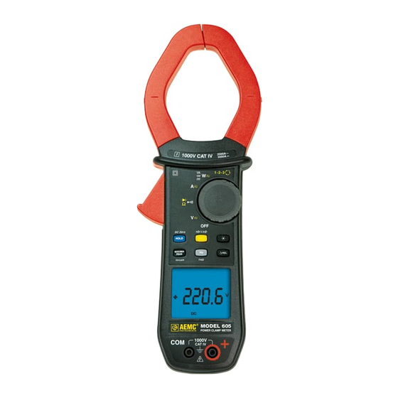
- Page 1 POWER CLAMP-ON METER EN G LI S H User Manual...
-
Page 3: Table Of Contents
CONTENTS RECEIVING YOUR SHIPMENT................8 ORDERING INFORMATION................8 PRESENTATION ..................9 THE ROTARY SWITCH................. 10 THE FUNCTION BUTTONS................11 THE DISPLAY ....................12 1.3.1 Display Symbols ................12 1.3.2 Measurement Capacity Exceeded (OL) ........13 THE TERMINALS................... 14 THE BUTTONS................... 15 BUTTON .................... - Page 4 3.10 STARTING CURRENT OR OVERCURRENT (True InRush™) MEASUREMENT ................... 28 3.11 POWER MEASUREMENTS W, VA, AND PF........29 3.11.1 Single-Phase Power Measurement..........29 3.11.2 Balanced 3-Phase Power Measurement........30 PHASE ROTATION MODE ..............31 3.12 3.13 FREQUENCY MEASUREMENT (H )............32 3.13.1 Frequency Measurement (V) ............
- Page 5 MAINTENANCE..................49 WARNING ...................... 49 CLEANING ..................... 49 REPLACEMENT OF THE BATTERIES............49 REPAIR AND CALIBRATION ..............50 TECHNICAL AND SALES ASSISTANCE..........50 LIMITED WARRANTY ................51 WARRANTY REPAIRS ................51...
- Page 6 Thank you for purchasing a Model 605 Clamp-on Meter. For best results from your instrument and for your safety, read the enclosed operating instructions carefully and comply with the precautions for use. These products must be only used by qualified and trained users.
- Page 7 PRECAUTIONS FOR USE This device complies with safety standards IEC-61010-1 and 61010-2-032 for voltages of 1000V in category IV at an altitude of less than 2000m, indoors, with a degree of pollution not exceeding 2. These safety instructions are intended to ensure the safety of persons and proper operation of the device.
-
Page 8: Receiving Your Shipment
Save the damaged packing container to substantiate your claim. ORDERING INFORMATION Clamp-on Meter Model 605 ............Cat. #2139.60 Includes set of 2 color-coded silicone insulated test leads, test probes and alligator clips, soft carrying case, 4x1.5V AA batteries and user manual. -
Page 9: Presentation
1 PRESENTATION The Clamp-on Meter Model 605 is a professional electrical measuring instrument that combines the following functions: Current measurement Measurement of InRush current / overcurrent (True InRush™) Voltage measurement Frequency measurement Measures harmonic distortion (THD) ... -
Page 10: The Rotary Switch
THE ROTARY SWITCH The rotary switch has six positions. To access the functions, set the switch to the desired function. The functions are described in the table below. Figure 2: The Function Rotary Switch Item Function See § OFF mode – Turns the clamp-on meter off AC, DC, AC+DC voltage measurement (V) Continuity test Resistance measurement ... -
Page 11: The Function Buttons
THE FUNCTION BUTTONS Figure 3: The Function Buttons Item Function See § Holds the last value on the display Zero correction A 3.9.2 AC+DC AC+DC Lead resistance compensation in the continuity and 3.6.1 ohmmeter functions Selects the type of measurement and configuration functions (AC, DC, AC+DC) Selection of single-phase or 3-phase measurement Enables/disables display backlighting... -
Page 12: The Display
THE DISPLAY Figure 4: The Display Item Function See § Mode selection display Display of the measurement value and unit 3.5 to 3.12 Display of the MAX/MIN/PEAK modes Type of measurement (AC or DC) Total 3-phase power measurements 3.11.2 Selected resistance mode display Low battery indication 1.3.1 Display Symbols... -
Page 13: Measurement Capacity Exceeded (Ol)
PEAK- Minimum peak value Balanced total 3-phase power measurement Volt Hertz Watt Ampere Percentage Ω Milli- prefix Kilo- prefix Reactive power Apparent power Power factor THDf Total harmonic distortion with respect to the fundamental Total harmonic distortion with respect to the true RMS THDr value of the signal. -
Page 14: The Terminals
THE TERMINALS The terminals are used as follows: Figure 5: The Terminals Item Function COM (black) Input Terminal Jack + Positive (red) Input Terminal Jack... -
Page 15: The Buttons
2 THE BUTTONS The buttons respond differently to short, long, and sustained presses. keys provide additional functions as well as the detection and acquisition of parameters complementary to the basic measurements. Each of these buttons can be used independently of the others or in conjunction with each other. -
Page 16: Yellow) Button (Second Function)
(YELLOW) BUTTON (SECOND FUNCTION) This button is used to select the type of measurement (AC, DC, AC+DC) and the second functions marked in yellow next to the relevant positions of the switch. It can also be used to modify the default values in the configuration mode (see §... -
Page 17: Button
BUTTON 2.4.1 Normal Mode This button activates the detection of the MAX, MIN, PEAK+ and PEAK- values of the measurements made. Max and Min are the extreme mean values in DC and the extreme RMS values in AC. Peak+ is the maximum instantaneous peak and Peak- is the minimum instantaneous peak. -
Page 18: The Max/Min Mode + Activation Of The Hold Mode
2.4.2 The MAX/MIN Mode + Activation of the HOLD Mode Successive presses on Function Displays the MAX/MIN/PEAK values detected before the button was pressed. short When the button is pressed, the last value is held on the display. NOTE: The HOLD function does not interrupt the acquisition of new MAX, MIN, PEAK values 2.4.3 Access to the True Inrush™... -
Page 19: Button
BUTTON This button is used to display the frequency measurements of a signal. NOTE: This button is not functional in the DC mode. 2.5.1 Normal Mode Successive Function presses on Displays: - The frequency of the signal measured - The present voltage (V) or current (A) measurement Displays: short... -
Page 20: Button
BUTTON This button is used to display and store the reference value in the unit of magnitude measured, or to display the differential and relative values, in %. NOTE: This button is not functional in phase rotation mode. Successive Function presses on Enters the ΔREL mode, to store, then display the reference value. -
Page 21: Use
3 USE INSTALLING THE BATTERIES Insert the batteries supplied with the device as follows: Using a screwdriver, unscrew the battery compartment cover (item 1) from the back of the housing. Insert the 4x1.5V AA batteries supplied (item 2), observing polarities. Close the battery compartment cover and screw it onto the housing. -
Page 22: Configuration
CONFIGURATION As a safety measure, and to avoid repeated overloads on the inputs of the device, configuration operations should only be performed when the device is disconnected from all dangerous voltages. 3.4.1 Configuring the Maximum Resistance for Continuity To configure the maximum resistance allowed for a continuity measurement: With the switch in the OFF position, hold the (yellow) button down while turning the switch to... -
Page 23: Default Configuration
2. To change the threshold, press the (yellow) button. The value flashes; each press on the (yellow) button displays the next value. To record the chosen threshold, apply a long press (>2s) on the (yellow) button. A confirmation beep is emitted. To exit from the configuration mode, turn the switch to another setting. -
Page 24: Continuity Test
The measured value is displayed on the screen. CONTINUITY TEST Warning: Before performing the test, make sure that the circuit is off and all capacitors have been discharged. Set the switch to ; the symbol is displayed. Connect the black lead to the COM terminal and the red lead to the "+" terminal. -
Page 25: Lead Resistance Compensation
3.6.1 Lead Resistance Compensation Warning: Before the compensation is executed, the MAX/MIN and HOLD modes must be disabled. To perform automatic compensation of the test lead resistance, proceed as follows: Short-circuit the leads connected to the meter. Hold the button down until the display unit indicates the lowest value. -
Page 26: Diode Test
DIODE TEST Warning: Before performing the diode test, make sure that the circuit is off and all capacitors have been discharged. Set the switch to and press the (yellow) button twice. The symbol is displayed. Connect the black lead to the COM terminal and the red lead to the "+" terminal. -
Page 27: Dc Or Ac+Dc Measurement
The measured value is displayed on the screen. 3.9.2 DC or AC+DC Measurement Set the switch to and select DC if the display does not indicate "0"; the DC zero must be corrected first. Step 1: Correction of DC Zero Important: The clamp must not be closed on the conductor during the DC zero correction. -
Page 28: Starting Current Or Overcurrent (True Inrush™) Measurement
3.10 STARTING CURRENT OR OVERCURRENT (True InRush™) MEASUREMENT NOTE: The measurement can be made only in AC or DC mode (AC+DC mode disabled). To measure a starting current or overcurrent, proceed as follows: Set the switch to , correct the DC zero (see §3.9.2), then clamp the jaws around the conductor to be measured. -
Page 29: Power Measurements W, Va, Var And Pf
3.11 POWER MEASUREMENTS W, VA, VAR AND PF This measurement is possible in single-phase or in balanced 3-phase. NOTE: If performing DC or AC+DC power measurements, correct the DC zero in current first (see § 3.9.2) For the power factor (PF) and the powers VA and var, the measurement is possible only in AC or AC+DC. -
Page 30: Balanced 3-Phase Power Measurement
3.11.2 Balanced 3-Phase Power Measurement Set the switch to and select VA, var, or PF by pressing the button until the desired choice is reached Press the (yellow) button until the symbol is displayed. The device automatically displays AC+DC. To select AC, DC, or AC+DC, press the (yellow) button until the desired choice is reached. -
Page 31: Phase Rotation Mode
3.12 PHASE ROTATION MODE This mode is used to determine the phase order of a 3-phase network using the "2-wire" method. To determine the phase order, proceed as follows: Step 1: Determining the Reference Period: Set the switch to . The rdy symbol is displayed; the device is ready for the first phase order determination measurement. -
Page 32: Frequency Measurement (Hz)
3.13 FREQUENCY MEASUREMENT (HZ) The frequency measurement is available in V, W and A for AC and AC+DC measurements. The measurement is based on a count of zero crossings (positive-going edges). 3.13.1 Frequency Measurement (V) To measure the frequency in voltage, proceed as follows: Set the switch to and press the button. -
Page 33: Frequency Measurement (W)
The measured value is displayed on the screen. 3.13.3 Frequency Measurement (W) Set the switch to and press the button four times. The Hz symbol is displayed; Select AC or AC+DC by pressing the (yellow) button until the desired choice is reached. Connect the black lead to the COM terminal and the red lead to the "+"... -
Page 34: Measurement Of The Level Of Harmonics (Thd) And
3.14 MEASUREMENT OF THE LEVEL OF HARMONICS (THD) AND OF THE FREQUENCY OF THE FUNDAMENTAL (NETWORK) The device measures the total harmonic distortion with respect to the fundamental (THD ) and the total harmonic distortion with respect to the true RMS value of the signal (THD ) in voltage and in current. - Page 35 The measurement is displayed on screen.
-
Page 36: Specifications
4 SPECIFICATIONS REFERENCE CONDITIONS Quantities of Influence Reference Conditions Temperature: 23°C ±2°C Relative humidity: 45% to 75% Supply voltage: 6.0V ±0.5V Frequency range of the applied signal: 45 to 65Hz Sine wave: pure Peak factor of the applied alternating signal: √2 Position of the conductor in the clamp: centered... -
Page 37: Ac Voltage Measurement
4.2.2 AC Voltage Measurement Measurement 0.15 to 100.0 to 1000V RMS Range 99.99V 999.9V 1400V peak (1) Specified Measurement 0 to 100% of the measurement range Range (2) 0.15 to 9.99V ± (1% R +10cts) Accuracy ± (1% R +3cts) 10.00 to 99.99V ±... -
Page 38: Dc Current Measurement
Specific Specifications in MAX/MIN mode in Voltage (from 10Hz to 1kHz and from 0.30V): Accuracy: add 1% R to the values of the previous table. Capture of the extreme: approximately 100ms. Specific Specifications in PEAK mode in voltage (from 10Hz to 1kHz): ... -
Page 39: Ac+Dc Intensity Measurement
4.2.6 AC+DC Intensity Measurement AC: 1000 to 2000A Measurement 0.15 to 100.0 to DC or PEAK: Range (2) 99.99A 999.9A 1000 to 3000A (1) Specified Measurement 0 to 100% of the measurement range Range Accuracy (2) 1500A ± (1% R+10cts) ±... -
Page 40: Resistance Measurement
4.2.9 Resistance Measurement 0.0 to 1000 to 10.00 to Measurement Range (1) 999.9 9999 99.99k Specified Measurement 1 to 100% of the 0 to 100% of the Range measurement range measurement range Accuracy ± (1% R +3cts) Resolution 0.1 1 10... -
Page 41: Active Ac Power Measurements
Note (1) - Display of O.L or ± O.L - Above 3000kW in single-phase (1000V x 3000A). - Above ±6000kW in REL mode. Note (2) Any applied voltage greater than 1000V causes the emission of an intermittent alarm beep to report a dangerous overload. Note (3) The measurement result may be affected by an instability linked to the current measurement (approximately 0.1A). -
Page 42: Active Ac+Dc Power Measurements
Consumed Generated 4.2.13 Active AC+DC Power Measurements Measurement 5 to 10.00 to 100.0 to 1000 to Range (2) (4) 9999W 99.99kW 999.9kW 3000kW (1) Specified 1 to 100% of the 0 to 100% Measurement measurement range of the measurement range Range 1000A 1000A... -
Page 43: Measurement Of Apparent Ac+Dc Power
Note (1) - Display of OL above 2000kVA in single-phase (1000V x 2000A) Notes (2), (3) and (4) of the previous § apply. 4.2.15 Measurement of Apparent AC+DC Power Measurement 5 to 10.00 to 100.0 to 1000 to Range (2) (4) 9999VA 99.99kVA 999.9kVA... -
Page 44: Measurement Of Reactive Ac+Dc Power
Quadrant 3: Reactive power Q sign - Quadrant 4: Reactive power Q sign – Note (7) With deformed signals (THD and harmonics), uncertainties are guaranteed since Φ > 30°: Add +1% for 10%<THD<20% Add +3% for 20%<THD<30% Add +5% for 30%<THD<40% 4.2.17 Measurement of Reactive AC+DC Power Measurement 5 to... -
Page 45: Frequency Measurements
Note 8 - Sign of the power factor according to the four-quadrant rule (§4.2.12): Quadrant 1: Power factor PF sign + (inductive system) Cos Φ sign + Quadrant 2: Power factor PF sign - (inductive system) Cos Φ sign - Quadrant 3: Power factor PF sign + (inductive system) -
Page 46: Specifications In Thdf
4.2.21 Specifications in THDf Measurement Range 0.0 to 1000% Specified Measurement 0 to 100% Range of the measurement range Accuracy ± (5% R ±2cts) in voltage ± (5% R ±5cts) in current Resolution 0.1% Note : The display is "----" if the input signal is too low (V<8V or I<9A) or if the frequency is less than 5Hz. -
Page 47: Mechanical Specifications
MECHANICAL SPECIFICATIONS Rigid polycarbonate shell with over-molded elastomer Housing: covering; UL94 V1 Polycarbonate Jaws: Opening: 2.36" (60mm) Clamping diameter: 2.36" (60mm) LCD display unit Screen: Blue backlighting Dimension: 1.6 x 1.9" (41 x 48mm) Dimension: 11.65 x 4.37 x 1.61" (296 x 111 x 41mm) Weight: 1.4 lbs (640g) with batteries POWER SUPPLY... -
Page 48: Environmental Variations
ENVIRONMENTAL VARIATIONS Influence Measuremen Condition of Range of Influence Influence Typical Influenced 0.1% R/10°C 0.1% R/10°C 0.5% R/10°C + 2ct -4° to +131°F Temperature 1% R/10°C T°C 1.5% R/10°C + 2ct (-20° to +55°C) (0.2% R +1°C)/10°C (0.3% R +2°C)/10°C ... -
Page 49: Maintenance
5 MAINTENANCE WARNING Remove the test leads on any input before opening the case. Do not operate the clamp-on meter without a battery case cover. To avoid electrical shock, do not attempt to perform any servicing unless you are qualified to do so. ... -
Page 50: Repair And Calibration
N.I.S.T. (includes calibration certificate plus recorded calibration data). ® ® Chauvin Arnoux , Inc. d.b.a. AEMC Instruments 15 Faraday Drive Dover, NH 03820 USA Tel: (800) 945-2362 (Ext. 360) (603) 749-6434 (Ext. -
Page 51: Limited Warranty
LIMITED WARRANTY The Model 605 is warranted to the owner for a period of three years from the date of original purchase against defects in manufacture. This limited ® warranty is given by AEMC Instruments, not by the distributor from whom it was purchased. - Page 52 ® ® Chauvin Arnoux , Inc. d.b.a AEMC Instruments 15 Faraday Drive • Dover, NH 03820 USA www.aemc.com 99-MAN 100370 v1 05/12...
Need help?
Do you have a question about the 605 and is the answer not in the manual?
Questions and answers