Siemens SINAUT ST7 System Manual
Station control system
Hide thumbs
Also See for SINAUT ST7:
- Operating instructions manual (161 pages) ,
- System manual (146 pages)
Table of Contents
Advertisement
Quick Links
SIMATIC NET
SINAUT ST7
Station control system
System Manual
Volume 1: System and Hardware
07/2009
C79000-G8976-C178-07
Preface
Introduction to the
SINAUT ST7 system
Network structures and
topologies
Installation guide
Installing and putting a
TIM into operation
Installing and putting a
SINAUT modem into
operation
1
2
3
4
5
Advertisement
Table of Contents

Related Manuals for Siemens SINAUT ST7


Summary of Contents for Siemens SINAUT ST7
- Page 1 Preface Introduction to the SINAUT ST7 system Network structures and topologies SIMATIC NET Installation guide SINAUT ST7 Installing and putting a Station control system TIM into operation Installing and putting a SINAUT modem into operation System Manual Volume 1: System and Hardware...
- Page 2 Note the following: WARNING Siemens products may only be used for the applications described in the catalog and in the relevant technical documentation. If products and components from other manufacturers are used, these must be recommended or approved by Siemens. Proper transport, storage, installation, assembly, commissioning, operation and maintenance are required to ensure that the products operate safely and without any problems.
-
Page 3: Preface
Ethernet TIM to the Internet via a DSL modem. – The time slot method can now also be configured with the "SINAUT ST7 configuration software for the PG/PC" as of V5.0 for a master TIM without DCF7 receiver, if a TIM 4R-IE with an Ethernet connection to an ST7cc/ST7sc PC is used as the master TIM. - Page 4 Note Documentation for the SINAUT ST1 system and older modules This release of the manual "SINAUT ST7" (volume 1 + 2) no longer has detailed information on the SINAUT ST1 system and the following older modules: • All previous TIM 3 modules: TIM 32, TIM 33, TIM 34 •...
- Page 5 SITRAIN - Siemens training for automation and industrial solutions With over 300 different courses, SITRAIN covers the entire Siemens product and system spectrum in the field of automation and drive technology. Advanced training tailored to your needs is also available. In addition to our classic range of courses, we also offer a combination of various training media and sequences.
-
Page 7: Table Of Contents
SINAUT ST7 configuration software for the PG ................60 1.9.3 Overview for ordering SINAUT ST7 software ................66 1.9.4 Installation of the SINAUT ST7 standard software package ............66 1.9.5 Uninstalling SINAUT ST7 software packages ................67 Station control system System Manual, 07/2009, C79000-G8976-C178-07... - Page 8 1.12.1 Standards and approvals for the TIM 3, TIM 4 and SINAUT modems ........78 1.12.1.1 Notes on the CE marks of SINAUT ST7 products ..............78 1.12.1.2 FM, UL and CSA approvals for all SINAUT ST7 products............80 1.12.1.3 Additional approvals for the MD3 analog dial-up modem ............80 1.12.2...
- Page 9 Table of contents 4.3.2 Front view of the TIM 4 with removed front panels..............148 4.3.3 LEDs of the TIM 3 / TIM 4......................149 4.3.4 Pinout of the X1 and X2 connectors ..................149 4.3.5 Standard connecting cables that can be connected to connector X1........151 4.3.6 View of the TIM 4 from above ....................154 4.3.7...
- Page 10 Table of contents ISDN dial-up modem MD4 ......................258 5.8.1 Indicators and connectors accessible from the front ..............258 5.8.2 Configuration switches accessible from above ................. 263 5.8.3 Connectors and configuration switches accessible from below..........267 5.8.4 Connecting the MD4 with a TIM and ISDN outlet ..............269 Installing and putting a SINAUT MD2, MD3, MD4 modem into operation........
-
Page 11: Introduction To The Sinaut St7 System
● SINAUT ST7cc, the PC control center (single or redundant) based on WinCC. This is a control center system for SINAUT ST7 specially tailored to the event-driven and time- stamped data transmission of the SINAUT system. -
Page 12: Components In A Sinaut St7 System
CPU. Components in a SINAUT ST7 system The SINAUT ST7 system is based on the S7-300 and S7 400 SIMATIC systems and on WinCC. It expands these systems by adding the special SINAUT hardware and software components listed below. -
Page 13: Sinaut Tim Communication Modules
– OPC server, the interface between ST7 and an OPC client – ST7sc Config, the configuration tool for ST7sc Note The standard software for SINAUT ST7 is described in detail in Volume 2 of this system manual. The SINAUT ST7cc and SINAUT ST7sc software packages are described in separate manuals. -
Page 14: Overview Of All Tim Variants
Introduction to the SINAUT ST7 system 1.3 SINAUT TIM communication modules It has two combined RS-232/RS-485 interfaces to which a classic WAN (dedicated line or dial-up network) can be connected via a suitable modem. It also has two RJ-45 interfaces that allow SINAUT communication over Ethernet-based networks (LAN or WAN). -
Page 15: The Tim 3V-Ie Variants
● With a TIM 3V-IE, an S7-300 CPU or a C7 control system can then handle SINAUT communication: – Via a classic SINAUT WAN network with SINAUT partners – Over an IP-based network (WAN or LAN) with SINAUT ST7 subscribers ● It has two interfaces: – RS-232 interface for connection of required WAN transmission equipment (classic... -
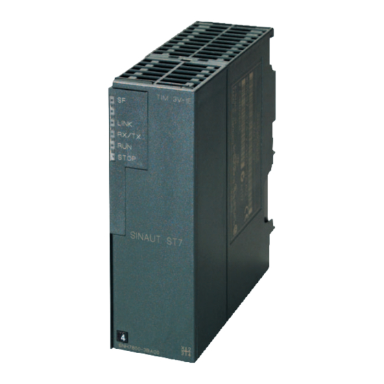
Page 16: Design Of The Tim 3V-Ie Variants
Introduction to the SINAUT ST7 system 1.3 SINAUT TIM communication modules Figure 1-1 SINAUT TIM 3V-IE communications module 1.3.3 Design of the TIM 3V-IE variants The TIM 3V-IE variants have all the advantages of the SIMATIC S7-300 system design: ● Compact design; single standard width of the SM modules of the SIMATIC S7-300 ●... -
Page 17: Technical Specifications Of The Tim 3V-Ie Variants
Introduction to the SINAUT ST7 system 1.3 SINAUT TIM communication modules RS232 interface (9-pin, male): WAN access point via external modem RJ45 interface: Ethernet access point 24 V Figure 1-2 Ports of the TIM 3V-IE or TIM 3V-IE Advanced 1.3.4... - Page 18 Introduction to the SINAUT ST7 system 1.3 SINAUT TIM communication modules TIM 3V-IE Permitted ambient conditions Operating temperature 0 °C through +60 °C • • Transport/storage temperature -40 °C through +70 °C • • Relative humidity Max. 95 % at +25 °C •...
- Page 19 Introduction to the SINAUT ST7 system 1.3 SINAUT TIM communication modules TIM 3V-IE Mode in dial-up network SINAUT ST7 protocol Spontaneous • • GPRS/MSC tunnel on the basis of the Spontaneous • • SINAUT ST7 protocol SINAUT ST1 protocol Spontaneous •...
- Page 20 Introduction to the SINAUT ST7 system 1.3 SINAUT TIM communication modules TIM 3V-IE Advanced Cable length RS-232 max. 6 m • • RS-485 max. 30 m • • RJ-45 max. 10 m • • Power supply 24 V DC; min. 20.4 V; max. 28.8 V...
- Page 21 Introduction to the SINAUT ST7 system 1.3 SINAUT TIM communication modules TIM 3V-IE Advanced Message memory on TIM Number of messages 32,000 messages • • Buffered • • Transmission protocols (RS-232) SINAUT ST7 Selectable protocols • SINAUT ST1 • Mode with dedicated line/wireless network...
-
Page 22: The Tim 4R-Ie
● This allows these devices to handle SINAUT communication: – Over any two classic SINAUT WAN networks with SINAUT partners – Over two IP-based networks (WAN or LAN) with SINAUT ST7 subscribers ● All four interfaces can be used at the same time for SINAUT communication. -
Page 23: Design Of The Tim 4R-Ie
Introduction to the SINAUT ST7 system 1.3 SINAUT TIM communication modules ● The SINAUT TD7 software is integrated on the TIM (TD7onTIM). It can be used when the TIM is installed as a CP in an S7-300. ● Modules can be replaced without a PG: –... -
Page 24: Technical Specifications Of The Tim 4R-Ie
Introduction to the SINAUT ST7 system 1.3 SINAUT TIM communication modules ● Can be operated without a fan ● A backup battery and a memory module (C-PLUG) can be installed as options. The following figure shows the ports of the TIM 4R-IE (schematic representation with front panel removed). - Page 25 Introduction to the SINAUT ST7 system 1.3 SINAUT TIM communication modules TIM 4R-IE Current consumption From backplane bus maximum 200 mA • • From 24 V DC typically 150 mA, max. 170 mA • • Power loss typically 4.6 W...
- Page 26 Introduction to the SINAUT ST7 system 1.3 SINAUT TIM communication modules TIM 4R-IE Local communication Over Ethernet interface with CPUs, PCs and Possible over TD7onCPU (for S7-400) and S7 • • other TIMs communication (for ST7cc/ST7sc and TIMs) When used in an S7-300 controller...
-
Page 27: The Tim 4 Variants
Introduction to the SINAUT ST7 system 1.3 SINAUT TIM communication modules TIM 4R-IE Asynchronous character format SINAUT ST7 protocol, polling or 10 or 11 bits • • spontaneous SINAUT ST7 protocol, 10 bits • • multi-master polling SINAUT ST1 protocol, polling 11 bits •... - Page 28 Introduction to the SINAUT ST7 system 1.3 SINAUT TIM communication modules ● This means that these devices can handle SINAUT communication over up to two SINAUT WAN networks. ● The two transmission paths can be different or identical. They can be operated independently or form a redundant transmission path.
-
Page 29: Design Of The Tim 4 Variants
Introduction to the SINAUT ST7 system 1.3 SINAUT TIM communication modules The following figure shows the ports of the two TIM 4R variants (schematic representation with covers removed). Combined RS232/RS485 interface (9-pin, male): First WAN access point via external modem... -
Page 30: Technical Specifications Of The Tim 4 Variants
Introduction to the SINAUT ST7 system 1.3 SINAUT TIM communication modules 1.3.10 Technical specifications of the TIM 4 variants Technical specifications of the TIM 4R / 4RD TIM 4R / TIM 4RD General Transmission rate 50 to 38,400 bps Interfaces... - Page 31 Introduction to the SINAUT ST7 system 1.3 SINAUT TIM communication modules TIM 4R / TIM 4RD Local communication in the rack of an S7-300 Over backplane bus with the S7-300-CPU Possible using TD7onCPU • • Over backplane bus with other TIMs in the Possible •...
-
Page 32: The Classic Sinaut St7 Modems
Introduction to the SINAUT ST7 system 1.4 The classic SINAUT ST7 modems The classic SINAUT ST7 modems The SINAUT ST7 MD2, MD3 and MD4 modems are built into an S7-300 housing just like the TIM modules. Figure 1-7 SINAUT MD modem 1.4.1... -
Page 33: Overview Of All Modem Variants And Accessories
Introduction to the SINAUT ST7 system 1.4 The classic SINAUT ST7 modems These modems can be attached to the serial modem port of a suitably equipped TIM module (TIM 3V-IE and all TIM 4 variants). Due to the design, the modems can be installed on an S7-300 standard rail just like the TIM modules. -
Page 34: Technical Specifications Of The Sinaut St7 Modems
Introduction to the SINAUT ST7 system 1.4 The classic SINAUT ST7 modems 1.4.3 Technical specifications of the SINAUT ST7 modems Technical specifications of the MD2 dedicated line modem Interfaces Attachment to dedicated line RJ-12 • • RS-232 attachment to DTE 9-pin D-sub male connector •... - Page 35 Introduction to the SINAUT ST7 system 1.4 The classic SINAUT ST7 modems Terminating resistor can be adjusted For 1200 and 2400 bps 600 ohms • • For 9600 and 19,200 bps 150 ohms • • For tapping point > 6 kilohms •...
- Page 36 Introduction to the SINAUT ST7 system 1.4 The classic SINAUT ST7 modems Permitted ambient conditions Operating temperature 0 °C through +60 °C • • Transport/storage temperature -40 °C through +70 °C • • Relative humidity Max. 95 % at +25 °C •...
- Page 37 Introduction to the SINAUT ST7 system 1.4 The classic SINAUT ST7 modems Compatible with SINAUT modems (as telephone modem) MD125 V.22 1200 bps, duplex • • V.22bis 2400 bps, duplex • MDM2425B DX • V.22bis 2400 bps, duplex • MD3 (hardware version < 4) •...
-
Page 38: Mobile Wireless Components
The latest SINAUT quadband mobile wireless modem makes operation in the GSM networks available worldwide(850, 900, 1800 and 1900 MHz range). SINAUT ST7 provides two options for data transmission over GSM mobile wireless: Station control system System Manual, 07/2009, C79000-G8976-C178-07... -
Page 39: Gsm Modem Md720-3
Introduction to the SINAUT ST7 system 1.5 Mobile wireless components 1. With the GSM modem MD720-3 – Data transmission on an "as necessary" basis by establishing a dial-up connection via a mobile wireless network (CSD: Circuit Switched Data) Dial-up connections are charged on a pay-by-time basis. - Page 40 1.5 Mobile wireless components Note The MD720-3 modem is used not only in SINAUT ST7 but also in SINAUT MICRO SC. In this case, S7-200 stations can transmit data over GPRS using the MD720-3. Along with the Ethernet TIMs as of firmware version V2.0, the MD720-3 can also transmit data via GPRS in SINAUT.
-
Page 41: Egprs/Gprs Modem Md741-1
Internet, for example DSL. A direct GPRS connection from GPRS modem to GPRS modem is not possible. Direct data exchange between two SINAUT ST7 stations that both communicate over GPRS is possible over a TIM module in the control center. - Page 42 Introduction to the SINAUT ST7 system 1.5 Mobile wireless components Figure 1-11 MD741-1 modem The following figure shows further details of the modem module. Figure 1-12 Connectors of the MD741-1 modem Station control system System Manual, 07/2009, C79000-G8976-C178-07...
-
Page 43: Ant794-4Mr Gsm/Gprs Antenna
Introduction to the SINAUT ST7 system 1.5 Mobile wireless components 1.5.4 ANT794-4MR GSM/GPRS antenna The ANT794-4MR GSM/GPRS antenna The quadband ANT794-4MR antenna is available for use in GSM/GPRS networks. To improve the field strength, it can be installed inside and outside buildings. - Page 44 Introduction to the SINAUT ST7 system 1.5 Mobile wireless components MD720-3 Transmit output power 850 MHz Max. 2 W • • 900 MHz Max. 2 W • • 1800 MHz Max. 1 W • • 1900 MHz Max. 1 W •...
- Page 45 Introduction to the SINAUT ST7 system 1.5 Mobile wireless components Technical specifications of the MD741-1 GPRS modem MD741-1 General Interfaces Application interface RJ-45 female (10/100 Mbps, TP, • • autocrossover) Service interface USB socket type A • • Antenna connector SMA female connector, •...
- Page 46 Introduction to the SINAUT ST7 system 1.5 Mobile wireless components MD741-1 Protocol IPSec (tunnel and transport mode) Encryption IPSec 3DES with 168 bits, IPSec AES with 128, 192 and 256 bits Internet Key Exchange (IKE) with main mode and quick mode...
-
Page 47: Ltop Overvoltage Protection Modules
Introduction to the SINAUT ST7 system 1.6 LTOP overvoltage protection modules Technical specifications of the ANT794-4MR GSM/GPRS antenna ANT794-4MR Mobile wireless networks GSM/GPRS Frequencies 850 MHz, 900 MHz, 1800 MHz, 1900 MHz, 2200 MHz Characteristics omnidirectional Antenna gain 0 dB <... -
Page 48: Technical Specifications Of The Ltop Overvoltage Protection Module
Introduction to the SINAUT ST7 system 1.6 LTOP overvoltage protection modules Figure 1-14 LTOP2 overvoltage protection module The LTOP overvoltage protection module is available in two variants: LTOP 1 Overvoltage protection module for use at the start or end of a 2-wire dedicated line. -
Page 49: Radio Clock Components
Introduction to the SINAUT ST7 system 1.7 Radio clock components LTOP Transmission range 300 Hz to 35 kHz Frequency-dependent attenuation Attenuation Frequency Transmission speed [bps] [dB] [Hz] MD100 MD124 1300 ... 3300 1200 1200 1200 2400 2400 5200 ... 8400 4800 10400 ... - Page 50 Introduction to the SINAUT ST7 system 1.7 Radio clock components The adapter cable is supplied with every TIM module with an integrated DCF77 radio clock. It can also be ordered as a spare part under the number listed in the following table.
-
Page 51: Gps Receiver
Introduction to the SINAUT ST7 system 1.7 Radio clock components If lightning protection 6NH9831-2AA is used, this should be installed whenever possible at the entrance to the building. To connect the lightning protection to the adapter cable of the TIM, use a separate antenna cable (BNC female connectors at both ends, similar to the antenna cable supplied with the indoor or outdoor antenna). - Page 52 Introduction to the SINAUT ST7 system 1.7 Radio clock components ● Software for configuring the GPS receiver (for Windows 95/98, NT, 2000, ME and XP) ● PC adapter cable, length 1.5 m ● Documentation Since the GPS antenna is an outdoor antenna, you should also install the available lightning protection device.
-
Page 53: Overview Of The Radio Clock Components
Introduction to the SINAUT ST7 system 1.7 Radio clock components adapter plug Adapter cable GPS outdoor antenna 6NH7 700-0AD15 for wall or mast mounting GPS kit incl. 25 m antenna cable 6NH9 831-8AA Complete GPS package for simulating the DCF77 time signal, comprising: - GPS receiver module - GPS outdoor antenna incl. -
Page 54: Technical Specifications Of The Radio Clock Components
Introduction to the SINAUT ST7 system 1.7 Radio clock components Short name Order no. Explanation GPS kit 6NH9831-8AA GPS complete package for simulating the DCF77 time signal, consisting of GPS receiver, GPS outdoor antenna including 25 m cable, BNC adapter connector, configuration software, PC adapter cable, and documentation. - Page 55 Introduction to the SINAUT ST7 system 1.7 Radio clock components DCF77 antennas Protection level at 6 kV 1.5/50 µs wave at input < 12 V Insertion loss for DCF77 signal Max. 3 dB Input / output BNC female / BNC female...
-
Page 56: Connecting Cables
Introduction to the SINAUT ST7 system 1.8 Connecting cables GPS receiver Outdoor antennas Type of antenna Micro-strip line with preamplifier Center frequency 1575.42 MHz Bandwidth 10 MHz View angle +10° above horizon Power supply (over antenna cable) 4.5 to 7 V DC... -
Page 57: Cable For Connecting Tim And Modem Modules
Cable for connecting two TIMs of the types TIM 3V-IE / TIM 4 over their RS-232 ports without modems (null modem). Cable length 6 m 6NH1701-7AN Cable for connecting a TIM 11 (RS-232) with one of the SINAUT ST7 MD2, MD3 or MD4 modems (RS-232). Cable length 2.5 m 6NH1701-7BK Cable for connecting a TIM011B (RS-232) with one of the SINAUT ST7 MD2, MD3 or MD4 modems (RS-232). -
Page 58: Wan Connecting Cables
Introduction to the SINAUT ST7 system 1.8 Connecting cables 1.8.2 WAN connecting cables A 6NH7700-xxx connecting cable ships with every MD modem. This can be used to connect the modem to the relevant WAN network. The connecting cables are also available as spares under the number shown. -
Page 59: The Sinaut St7 Standard Software Package
1.9 The SINAUT ST7 standard software package The SINAUT ST7 standard software package The SINAUT ST7 standard software package comes on a CD-ROM and is made up of two parts: 1. The SINAUT TD7 library that contains blocks for the S7 CPU 2. -
Page 60: Sinaut St7 Configuration Software For The Pg
● The SINAUT ST 7 configuration tool is used for project-wide functions such as SINAUT connection configuration and SINAUT subscriber management. ● The SINAUT ST7 diagnostics and service tool. In addition to the diagnostic functions familiar from STEP 7. Using the service tool, it is, for example, possible to load new software on a TIM. - Page 61 Introduction to the SINAUT ST7 system 1.9 The SINAUT ST7 standard software package SINAUT ST7 You can select the required TIM module from the folder and install it in the S7 rack. You can then open a properties dialog and assign the required parameters to the module.
- Page 62 The SINAUT ST7 configuration tool Unlike the two managers mentioned up to now, the SINAUT ST7 configuration tool does not expand one of the standard STEP 7 tools but is a separate configuration tool embedded in the STEP 7 environment.
- Page 63 Introduction to the SINAUT ST7 system 1.9 The SINAUT ST7 standard software package Connection configuration The first step is to use the tool to specify the SINAUT subscribers (ST7-CPU, ST7cc/ST7sc) between which a connection is necessary. The tool provides you with a selection of all theoretically possible connections in the right-hand pane of the split window.
- Page 64 Introduction to the SINAUT ST7 system 1.9 The SINAUT ST7 standard software package The following figure illustrates how SMS messages can be configured conveniently in subscriber administration. The configuration results in the automatic generation of data blocks containing texts and the corresponding function blocks that are saved in the block directory on the relevant CPUs.
- Page 65 Introduction to the SINAUT ST7 system 1.9 The SINAUT ST7 standard software package The SINAUT ST7 diagnostics and service tool In addition to the diagnostic functions familiar from STEP 7, you also have access here to SINAUT-specific diagnostic information. Using the service tool, it is, for example, possible to load new software on a TIM.
-
Page 66: Overview For Ordering Sinaut St7 Software
● The installed STEP 7 software must be version 5.4 SP4 or higher. Autorun If the feature is activated on your PC/PG, the SINAUT ST7 setup program starts automatically when you insert the CD. Otherwise, use the Explorer to open the root directory Setup.exe on the CD and click on the application. -
Page 67: Uninstalling Sinaut St7 Software Packages
During installation, the setup program will prompt you for any necessary information. The installation programs perform the following individual operations: ● The programs and data supplied with SINAUT ST7 are copied to the correct locations in the STEP 7 system. -
Page 68: Sinaut St7Cc, The Add-On For Wincc
Introduction to the SINAUT ST7 system 1.10 SINAUT ST7cc, the add-on for WinCC 1.10 SINAUT ST7cc, the add-on for WinCC 1.10.1 Area of application SINAUT ST7cc is the ideal control center system based on SIMATIC WinCC for SINAUT ST7. It is specially designed for event-driven and time-stamped data transmission in the SINAUT system. -
Page 69: The Special Properties Of Sinaut St7Cc
The special properties of SINAUT ST7cc Telecontrol master with user-friendly diagnostics ● Direct connection of SINAUT ST7 TIMs to ST7cc over MPI and Ethernet. A separate CPU as telecontrol master is not required. ● Availability of the most important status information of each SINAUT subscriber with visualization in WinCC using provided station typicals (picture typicals and faceplates) ●... -
Page 70: System Prerequisites
Introduction to the SINAUT ST7 system 1.10 SINAUT ST7cc, the add-on for WinCC ● Counted values – Overflow handling with absolute counters – Counted value scaling using factors – Calculation of correctly timed interval quantities – Entry of currently accumulating interval quantities in the assigned WinCC tags –... - Page 71 *) This can also be a runtime package if no configuration is necessary on the end computer. Connecting SINAUT stations One or more SINAUT ST7 TIM communications processors are connected either over the MPI S7 standard bus or Ethernet. ST7cc...
-
Page 72: Ordering Data For Sinaut St7Cc
Introduction to the SINAUT ST7 system 1.10 SINAUT ST7cc, the add-on for WinCC ● For TIMs (TIM 4x), connected to the ST7cc PC over MPI, time synchronization is possible only with a TIM equipped with a DCF77 receiver. This then serves as the central time synchronization source for the ST7cc PC and all other TIMs connected to MPI. -
Page 73: Technical Specifications Of Sinaut St7Cc
Introduction to the SINAUT ST7 system 1.11 SINAUT ST7sc SCADA Connect software 1.10.5 Technical specifications of SINAUT ST7cc SINAUT ST7cc Operating systems Windows XP Prof. SP1, SP2, Windows 2000 Prof. SP1, 2, 3, 4 Windows Server 2003 Standard Edition + SP1 WinCC versions WinCC V5.0 SP2 or higher... -
Page 74: The Special Properties Of Sinaut St7Sc
Introduction to the SINAUT ST7 system 1.11 SINAUT ST7sc SCADA Connect software Figure 1-27 Control center system and SINAUT ST7sc with attached SINAUT stations 1.11.1 The special properties of SINAUT ST7sc Acquiring process data The SINAUT station acquires the process data when it changes and transfers this to SINAUT ST7sc over the WAN. - Page 75 Introduction to the SINAUT ST7 system 1.11 SINAUT ST7sc SCADA Connect software client later, ST7sc includes the "item buffering" technique that helps to avoid data loss on the way to the OPC client, as follows: ● When the OPC "Data Access" interface that represents a process image is updated by the SINAUT stations more quickly than the client can read it.
-
Page 76: System Prerequisites
Ethernet, or they are installed on the same PC as SINAUT ST7sc. Connecting SINAUT stations One or more SINAUT ST7 TIM communications processors are connected either over the MPI S7 standard bus or Ethernet. Client... -
Page 77: Ordering Data For Sinaut St7Sc
Introduction to the SINAUT ST7 system 1.11 SINAUT ST7sc SCADA Connect software When supplying the current time of day, the following situations must be distinguished: ● For TIMs (TIM 4x), connected to the ST7sc PC over MPI, time synchronization is possible only with a TIM equipped with a DCF77 receiver. -
Page 78: Technical Specifications Of Sinaut St7Sc
Standards and approvals of SINAUT ST7 products 1.12.1 Standards and approvals for the TIM 3, TIM 4 and SINAUT modems 1.12.1.1 Notes on the CE marks of SINAUT ST7 products List of SINAUT ST7 products Short name Order no. TIM 4R... - Page 79 Introduction to the SINAUT ST7 system 1.12 Standards and approvals of SINAUT ST7 products EU Directive EMC 2004/108/EEC The products listed above comply with the requirements of the EU Directive 2004/108/EEC "Electromagnetic Compatibility" and the Harmonized European Standards (EN) published in this connection.
-
Page 80: Fm, Ul And Csa Approvals For All Sinaut St7 Products
FM, UL and CSA approvals for all SINAUT ST7 products FM approval The SINAUT ST7 products included in the "List of SINAUT ST7 products" are certified as follows: FM Approval according to Factory Mutual Approval Standard Class Number 3611, Class I,... - Page 81 Introduction to the SINAUT ST7 system 1.12 Standards and approvals of SINAUT ST7 products Approval for Europe Approval regulations The MD3 is intended for connection to the analog public telecommunication network. In Germany, the device is connected with the standard TAE6 connecting cable with N coding supplied with the device.
- Page 82 Introduction to the SINAUT ST7 system 1.12 Standards and approvals of SINAUT ST7 products advance. But if advance notice is not practical, you will be notified as soon as possible. You will be informed of your right to file a complaint with the FCC.
-
Page 83: Standards And Approvals For The Tim 3V-Ie Variants And The Tim 4R-Ie
Introduction to the SINAUT ST7 system 1.12 Standards and approvals of SINAUT ST7 products Note The Ringer Equivalence Number (REN) assigned to each terminal device provides an indication of the maximum number of terminals allowed to be connected to a telephone interface. - Page 84 Introduction to the SINAUT ST7 system 1.12 Standards and approvals of SINAUT ST7 products ● 2004/108/EEC "Electromagnetic Compatibility" (EMC Directive) ● 94/9/EC "Equipment and protective systems intended for use in potentially explosive atmospheres" (Explosion Protection Directive) You will find the EC Declaration of Conformity for this product on the Internet at the following address: http://support.automation.siemens.com/WW/view/en/10805878...
- Page 85 Introduction to the SINAUT ST7 system 1.12 Standards and approvals of SINAUT ST7 products Machinery directive The product remains a component in compliance with Article 4(2) of the EC Machinery Directive 98/37/EEC. According to the machinery directive, we are obliged to point out that the product described is intended solely for installation in a machine.
- Page 86 Introduction to the SINAUT ST7 system 1.12 Standards and approvals of SINAUT ST7 products CULus approval, hazardous location CULUS Listed 7RA9 IND. CONT. EQ. FOR HAZ. LOC. Underwriters Laboratories Inc. complying with ● UL 508 (Industrial Control Equipment) HAZ. LOC.
- Page 87 Introduction to the SINAUT ST7 system 1.12 Standards and approvals of SINAUT ST7 products FM approval Factory Mutual Approval Standard Class Number 3611, Class I, Division 2, Group A, B, C, WARNING Personal injury and property damage can occur. In hazardous areas, personal injury or property damage can result if you create or break an electrical circuit during operation of a SINAUT product (for example, by means of plug-in connections, fuses, switches).
-
Page 89: Network Structures And Topologies
The following overview shows you the network structures that can be implemented with SINAUT ST7 in a WAN and on Industrial Ethernet. For each network configuration, you will also see the protocols and modes with which SINAUT can handle communication over the network. -
Page 90: Configurations
Network structures and topologies 2.2 Configurations Configurations The symbols used in the following configurations represent the various modules with their LAN or WAN interfaces. Note Notes on TIM 4 / TIM 4R-IE • The two WAN interfaces of a TIM 4R / TIM 4RD can both have the same function (for example 2 x master) or different functions (for example node + master). - Page 91 Network structures and topologies 2.2 Configurations Wireless Ethernet communication Figure 2-2 Wireless Ethernet communication Wireless Ethernet communication with TIM 3V-IE in master stations and stations Figure 2-3 Wireless Ethernet communication with TIM 3V-IE in master stations and stations Station control system System Manual, 07/2009, C79000-G8976-C178-07...
- Page 92 Network structures and topologies 2.2 Configurations IP-based communication via DSL Figure 2-4 IP-based communication via DSL Station control system System Manual, 07/2009, C79000-G8976-C178-07...
- Page 93 Network structures and topologies 2.2 Configurations IP-based communication via GPRS with simple security (simple Internet communication) SINAUT ST7cc/sc 4R-IE router Dedicated line Industrial to Internet, e.g. Ethernet DSL connection with flat rate and preferably Control center fixed IP address VPN tunnel (MSC) VPN tunnel (MSC) Internet GPRS network...
- Page 94 Network structures and topologies 2.2 Configurations IP-based communication via GPRS with higher security SINAUT Security ST7cc/sc Module 4R-IE SCALANCE S DSL router Industrial Dedicated line Ethernet to Internet, e.g. DSL connection Control center with flat rate and Firewall preferably fixed IP address VPN tunnel VPN tunnel Internet...
-
Page 95: Configurations With Classic Wan
Network structures and topologies 2.2 Configurations 2.2.2 Configurations with classic WAN Dedicated line configurations Dedicated line configurations Notes Network type: Point-to-point Protocol: SINAUT ST7 and ST1 Mode: Polling Network type: Star Protocol: SINAUT ST7 and ST1 Mode: Polling Network type:... - Page 96 Network structures and topologies 2.2 Configurations Radio network configuration Radio network configurations Notes Network type: Point-to-point Protocol: SINAUT ST7 and ST1 Mode: Polling or Network type: Star Protocol: SINAUT ST7 and ST1 Mode: Polling or polling with time slot procedure...
- Page 97 Dial-up network configuration Dial-up network configurations Notes Network type: Analog telephone or digital ISDN *) Protocol: SINAUT ST7 and ST1 Mode: Spontaneous *) A combination of analog and ISDN connections is not possible if SINAUT modems are used. Special hybrid modems are required for this purpose.
- Page 98 Examples of redundant configurations Redundant network configurations (examples) Notes Network Redundant point-to-point type: connection via two dedicated lines Protocol: SINAUT ST7 and ST1 Mode: Polling Network Redundant star network via type: 2 dedicated lines each, mixed with non-redundantly connected stations...
-
Page 99: Installation Guide
Installation guide Horizontal and vertical installation Horizontal and vertical installation You can operate the SINAUT ST7 components both in horizontally and in vertically installed racks. Permitted ambient temperature The SINAUT ST7 components can be operated in the same temperature range specified for the S7-300. -
Page 100: Current Consumption And Power Loss Of The Sinaut St7 Components
SINAUT ST7 station control device. Current consumption and power loss The following table lists the current consumption and power loss of the SINAUT ST7 TIM and modem components. Table 3- 3... - Page 101 Installation guide 3.3 Current consumption and power loss of the SINAUT ST7 components Short module name Module order no. Current consumption Current consumption Power loss (nominal) from backplane bus from 24 V load power (max.) supply MD741-1 6NH9 741-1AA00 137...182 mA ***)
-
Page 102: Installing The Tim 3V-Ie Variants In An S7-300
Installation guide 3.4 Installing the TIM 3V-IE variants in an S7-300 Result The following results can be derived from the table above: 1. Current consumption from S7-300 backplane bus: The current consumption of the signal and TIM modules from the backplane bus amounts to a total of 270 mA. - Page 103 Installation guide 3.4 Installing the TIM 3V-IE variants in an S7-300 The following CPU lists also include older CPU types that can no longer be ordered as new devices but that nevertheless may still be in use in the field. These are shown in parentheses.
- Page 104 Installation guide 3.4 Installing the TIM 3V-IE variants in an S7-300 (C7-626/P DP) as of 6ES7 626-2DG02-0AB3 (C7-633/P) as of 6ES7 633-1DF00-0AB3 (C7-633/DP) as of 6ES7 633-2BF00-0AB3 (C7-634/P) as of 6ES7 634-1DF00-0AB3 (C7-634/DP) as of 6ES7 634-2BF00-0AB3 C7-635 Key as of 6ES7 635-2EC00-0AB3 C7-635 Touch as of 6ES7 635-2EB00-0AB3 C7-636 Key...
- Page 105 Installation guide 3.4 Installing the TIM 3V-IE variants in an S7-300 S7-300 with access to a classic WAN To implement classic WAN access for an S7-300, you can use either a TIM 3V-IE or a TIM 3V-IE Advanced. The following figure shows such a configuration. Figure 3-1 SIMATIC S7-300 with TIM 3V-IE with 1 connection to classic WAN over an external MDx modem...
- Page 106 Installation guide 3.4 Installing the TIM 3V-IE variants in an S7-300 ● DSL router ● Backbone transmission systems such as OTN, PCM30 Two examples are illustrated below. Figure 3-3 SIMATIC S7-300 with TIM 3V-IE connected to an FO cable over a SCALANCE X-200 Figure 3-4 SIMATIC S7-300 with TIM 3V-IE, 1 GPRS access via MD741-1 modem S7-300 with two WAN attachments...
- Page 107 Installation guide 3.4 Installing the TIM 3V-IE variants in an S7-300 Instead of the MDx SINAUT modem, other modems with an RS-232 interface can also be used, for example wireless devices or the SINAUT GSM modem MD720-3. S7-300 with maximum configuration A maximum of one (standard) TIM 3V-IE can be inserted in an S7-300.
- Page 108 Installation guide 3.4 Installing the TIM 3V-IE variants in an S7-300 Connection to ST7cc / ST7sc over MPI The following figure shows a configuration in which the TIM is connected to the PC over the MPI interface of its CPU. This is possible only when one of the CPU modules listed in the section "Installation of the TIM 4 as CP in an S7-300 (Page 121)"...
-
Page 109: Installing The Tim 4R-Ie In An S7-300
Installation guide 3.5 Installing the TIM 4R-IE in an S7-300 Connection to ST7cc / ST7sc over Ethernet The following figure shows a configuration in which the TIM is connected to the PC over its Ethernet interface. As of ST7cc V2.5 or ST7sc V1.1, the TIM can exchange data directly with ST7cc/ST7sc over its Ethernet interface. - Page 110 Installation guide 3.5 Installing the TIM 4R-IE in an S7-300 constraints that must be taken into account relating to the way in which data exchange between the TIM and the CPU in the rack is handled (the SINAUT program). For the TIM 4R-IE, there are two options: 1.
- Page 111 Installation guide 3.5 Installing the TIM 4R-IE in an S7-300 Compact CPU modules CPU 312C as of 6ES7 312-5BD00-0AB0 CPU 313C as of 6ES7 313-5BE00-0AB0 CPU 313C-2PtP as of 6ES7 313-6BE00-0AB0 CPU 313C-2DP as of 6ES7 313-6CE00-0AB0 CPU 314C-2PtP as of 6ES7 314-6BF00-0AB0 CPU 314C-2DP as of 6ES7 314-6CF00-0AB0 Instead of an S7-300 standard or compact CPU, one of the following C7 control systems...
- Page 112 Installation guide 3.5 Installing the TIM 4R-IE in an S7-300 NOTICE Since the SINAUT-Modems MD2, MD3 and MD4 do not have an S7-300 backplane bus, an S7-300 SM, FM or CP module that communicates with the CPU over this backplane bus must not be inserted to the right of the modem! Note In all of the sample configurations of the S7-300, it is assumed that a 24 V power supply is...
- Page 113 Installation guide 3.5 Installing the TIM 4R-IE in an S7-300 Figure 3-9 SIMATIC S7-300 with TIM 4R-IE, 1 connection to WAN and 1 connection to Ethernet as redundant routes to the stations and to the master station Standalone TIM 4R-IE as master station or node station The following figure shows the use of the TIM 4R-IE in a standalone configuration;...
- Page 114 Installation guide 3.5 Installing the TIM 4R-IE in an S7-300 Master station Node station Internet GPRS Station Figure 3-10 TIM 4R-IE in a master station or node station, redundant connection to subsidiary station; one path as dedicated line, the second over GPRS and Internet Station control system System Manual, 07/2009, C79000-G8976-C178-07...
- Page 115 Installation guide 3.5 Installing the TIM 4R-IE in an S7-300 Direct communication over TIM 4R-IE and other TIM modules As described above, with a TIM 4R-IE, direct communication is possible between all stations on all networks connected to the TIM. If there are other TIM modules on Ethernet or on the MPI bus in addition to the TIM 4R-IE, direct communication can also be extended to the networks of the other TIMs.
- Page 116 Installation guide 3.5 Installing the TIM 4R-IE in an S7-300 Figure 3-12 Direct communication over a TIM 4 (standalone), MPI and a TIM 4R-IE, installed in an S7-300; communication within the S7-300 over the backplane bus (direct communication paths are shown as dashed lines) A further example shows the path of direct communication between stations connected to a TIM 4R-IE and a TIM 4 or TIM 3.
- Page 117 Installation guide 3.5 Installing the TIM 4R-IE in an S7-300 Figure 3-13 Direct communication over a TIM 4R-IE and a TIM 3 or TIM 4 in an S7-300 rack; communication within the S7-300 over the backplane bus (direct communication paths are shown as dashed lines) In this example, the CPU of station 3 (not shown in figure) on WAN 3 communicates with the master station and one or more stations on WAN 1 over a TIM 3 or TIM 4 and the TIM 4R-IE.
-
Page 118: Standalone Tim 4R-Ie With An S7-400 Or Pc
Installation guide 3.6 Standalone TIM 4R-IE with an S7-400 or PC Standalone TIM 4R-IE with an S7-400 or PC Introduction In standalone mode, in other words, without an S7-300-CPU, the TIM 4R-IE is ideally suited as a SINAUT communications processor for an S7-400 or for the PC of the ST7cc or ST7sc control center. - Page 119 Installation guide 3.6 Standalone TIM 4R-IE with an S7-400 or PC TIM 4R-IE with SIMATIC S7-400 The TIM 4R-IE is connected to a SIMATIC S7-400 over one of the Ethernet ports of the TIM. With the S7-400, an Ethernet CP is used as the interface. Direct connection of the TIM 4R-IE to the PROFINET interface of an S7-400 CPU is also possible.
- Page 120 Installation guide 3.6 Standalone TIM 4R-IE with an S7-400 or PC the two other networks might be classic SINAUT networks such as dedicated line or telephone network. Figure 3-15 SINAUT ST7cc / ST7sc control center system with TIM 4R-IE connected over Ethernet, 1 connection to IP-based WAN or LAN, 2 classic connections to WAN, for example over SINAUT MDx modems Other modems with an RS-232 or RS-485 interface can be used instead of the SINAUT MDx...
-
Page 121: Installation Of The Tim 4 As Cp In An S7-300
Installation guide 3.7 Installation of the TIM 4 as CP in an S7-300 Figure 3-16 Redundant SINAUT ST7cc / ST7sc control center system with TIM 4R-IE connected over Ethernet, 1 connection to IP-based WAN or LAN, 2 classic connections to WAN, for example over SINAUT MDx modems Installation of the TIM 4 as CP in an S7-300 Introduction This section explains the installation of the various TIM 4 modules in an S7-300. - Page 122 Installation guide 3.7 Installation of the TIM 4 as CP in an S7-300 Standard CPU modules CPU 312 as of 6ES7 312-1AE13-0AB0 CPU 314 as of 6ES7 314-1AE02-0AB0 (CPU 314 IFM) as of 6ES7 314-5AE02-0AB0 (CPU 315) as of 6ES7 315-1AF01-0AB0 CPU 315-2 DP as of 6ES7 315-2AF01-0AB0 CPU 315F-2 DP...
- Page 123 Installation guide 3.7 Installation of the TIM 4 as CP in an S7-300 Installation in a rack With standard and compact CPU modules, the TIM can be inserted into any of the racks 0 to 3 but only in expansion racks 1 to 3 if these racks are connected to the CPU over the IM 360/IM 361 interface modules.
-
Page 124: Standalone Tim 4 With An S7-400 Or Pc
Installation guide 3.8 Standalone TIM 4 with an S7-400 or PC Figure 3-17 SIMATIC S7-300 with TIM 4, Two connections to WAN via external MDx modems The achieve greater clarity, the TIM 4 and MDx (1) modem are installed directly beside each other in rack 0. - Page 125 Installation guide 3.8 Standalone TIM 4 with an S7-400 or PC Installation When used as a standalone, the TIM 4 is normally installed on a separate S7-300 standard rail, when necessary along with a power supply module to supply the TIM with 24 V. If the SINAUT MD2, MD3 or MD4 modems are used, they can also be installed on the same rail.
- Page 126 Installation guide 3.8 Standalone TIM 4 with an S7-400 or PC S7-400 with one WAN attachment The following figure shows the simplest configuration for an S7-400 with one connection to a WAN over a TIM 4. Figure 3-18 SIMATIC S7-400 with TIM 4 on MPI bus, 1 connection a WAN A suitable modem or other transmission device can be connected to the combined RS- 232/RS-485 interface of the TIM 4.
- Page 127 Installation guide 3.8 Standalone TIM 4 with an S7-400 or PC S7-400 with two WAN attachments The TIM 4 and two MD2, MD3 or MD4 SINAUT modems are mounted on a separate S7-300 rail. The TIM 4 is connected to the CPU over its MPI interface. The following figure shows the configuration described.
- Page 128 Installation guide 3.8 Standalone TIM 4 with an S7-400 or PC S7-300 and S7-400 with common WAN attachment Since a TIM 4 can communicate not only with one CPU but with several over MPI, a SINAUT station can also be configured as shown in the following figure. Here, it does not matter whether these CPUs are of the type S7-400 or S7-300.
- Page 129 Installation guide 3.8 Standalone TIM 4 with an S7-400 or PC The following figure shows the simplest configuration for a SINAUT ST7cc or ST7sc control center system with one (1) connection to a WAN. Figure 3-21 SINAUT ST7cc / ST7sc control center systems with TIM 4 on MPI bus, 1 connection to WAN via MDx modem In much the same way as with an S7-400, ST7cc / ST7sc can also have two connections to a WAN.
- Page 130 Installation guide 3.8 Standalone TIM 4 with an S7-400 or PC telecontrol network. This controller could, for example, be used to display data received from the stations on a panel or console or for emergency input by an operator if ST7cc / ST7sc failed.
-
Page 131: Installing And Putting A Tim Into Operation
Installing and putting a TIM into operation Design of the TIM 3V-IE variants This section explains the design of the TIM 3V-IE variants. 4.1.1 Front view of the TIM 3V-IE variants with closed front panel Figure 4-1 Front view of a TIM 3V-IE variant with closed front panel Station control system System Manual, 07/2009, C79000-G8976-C178-07... -
Page 132: Front View Of The Tim 3V-Ie Variants With Front Panel Removed
Installing and putting a TIM into operation 4.1 Design of the TIM 3V-IE variants 4.1.2 Front view of the TIM 3V-IE variants with front panel removed Figure 4-2 Front view of a TIM 3V-IE variant with front panel removed For information on the RESET button, refer to "Default startup" in the section "Startup activities of the TIM 3V-IE variants". - Page 133 Installing and putting a TIM into operation 4.1 Design of the TIM 3V-IE variants LED no. Labeling Relevant TIM port Description LINK Ethernet Connection to Ethernet LED is lit when there is a physical connection to Ethernet. LED is off when there is no physical connection to Ethernet. RX/TX Ethernet Data flow over Ethernet...
-
Page 134: Pinout Of The Ports
Installing and putting a TIM into operation 4.1 Design of the TIM 3V-IE variants 4.1.4 Pinout of the ports RS-232 interface The connector for the RS-232 port is designed as a 9-pin D-sub miniature connector (male). The pinout is shown in the following table. As an RS-232 port, the pinout corresponds to that of a standardized PC connector. -
Page 135: Standard Connecting Cables For The Tim 3V-Ie Variants
6NH7701-4AL Cable for connecting the TIM 3V-IE (RS-232) to one of the SINAUT ST7 modems MD2, MD3 or MD4 (RS-232). Also suitable for linking these modems to a SIMATIC point- to-point CP such as the CP 340, CP 341 or CP 441 with RS-232 interface. - Page 136 Installing and putting a TIM into operation 4.1 Design of the TIM 3V-IE variants Figure 4-3 Assembly of the standard connecting cable 6NH7701-4AL Figure 4-4 Assembly of the standard connecting cable 6NH7701-5AN Figure 4-5 Assembly of the standard connecting cable 6NH7701-4BN Station control system System Manual, 07/2009, C79000-G8976-C178-07...
- Page 137 Installing and putting a TIM into operation 4.1 Design of the TIM 3V-IE variants Figure 4-6 Assembly of the standard connecting cable 6NH7701-0AR Connecting cables for connecting to Ethernet There is no standard connecting cable available in the SINAUT range to connect the TIM 4R-IE to Ethernet.
-
Page 138: Design Of The Tim 4R-Ie
Installing and putting a TIM into operation 4.2 Design of the TIM 4R-IE Design of the TIM 4R-IE 4.2.1 Front view of the TIM 4R-IE with closed front panel 6NH7800-4BA00 Figure 4-8 Front view of the TIM 4R-IE with closed front panel For information on the RESET button, refer to "Default startup"... -
Page 139: Front View Of The Tim 4R-Ie With Removed Front Panel
Installing and putting a TIM into operation 4.2 Design of the TIM 4R-IE 4.2.2 Front view of the TIM 4R-IE with removed front panel Figure 4-9 Front view of the TIM 4R-IE with removed front panel On the rear of the housing, there is an opening for the optional C-PLUG. The configuration data of the TIM 4R-IE can be stored on the C-PLUG. -
Page 140: Leds Of The Tim 4R-Ie
Installing and putting a TIM into operation 4.2 Design of the TIM 4R-IE 4.2.3 LEDs of the TIM 4R-IE The following table summarizes the meaning of the LEDs during normal operation. The display during startup is explained in the section "Startup activities of the TIM 4R-IE (Page 175)". -
Page 141: Pinout Of The Ports
Installing and putting a TIM into operation 4.2 Design of the TIM 4R-IE LED no. Labeling Relevant TIM port Type of WAN Description driver RXD2 RS-232 interface 2 Dedicated line Receive data As long as receive level (DCD) is detected, the LED is lit and goes off while a message is being received (RXD). - Page 142 Installing and putting a TIM into operation 4.2 Design of the TIM 4R-IE Table 4- 8 Pinout of the connector of the combined RS-232/RS-485 port Illustration Pin no. Signal name Signal direction Remark Input Input Switching over to RS-485 in the configuration Output Switching over to RS-485 in the configuration...
-
Page 143: Standard Connecting Cables For The Tim 4R-Ie
6NH7701-4AL Cable for connecting the TIM 3V-IE (RS-232) to one of the SINAUT ST7 modems MD2, MD3 or MD4 (RS-232). Also suitable for linking these modems to a SIMATIC point- to-point CP such as the CP 340, CP 341 or CP 441 with RS-232 interface. - Page 144 Installing and putting a TIM into operation 4.2 Design of the TIM 4R-IE Figure 4-10 Assembly of the standard connecting cable 6NH7701-4AL Figure 4-11 Assembly of the standard connecting cable 6NH7701-4DL Station control system System Manual, 07/2009, C79000-G8976-C178-07...
- Page 145 Installing and putting a TIM into operation 4.2 Design of the TIM 4R-IE Figure 4-12 Assembly of the standard connecting cable 6NH7701-5AN Figure 4-13 Assembly of the standard connecting cable 6NH7701-4BN Station control system System Manual, 07/2009, C79000-G8976-C178-07...
- Page 146 Installing and putting a TIM into operation 4.2 Design of the TIM 4R-IE Figure 4-14 Assembly of the standard connecting cable 6NH7701-0AR Connecting cables for connecting to Ethernet There is no standard connecting cable available in the SINAUT range to connect the TIM 4R-IE to Ethernet.
-
Page 147: Design Of The Tim 3 And Tim 4 Modules
Installing and putting a TIM into operation 4.3 Design of the TIM 3 and TIM 4 modules Design of the TIM 3 and TIM 4 modules Introduction This section explains the structure of the TIM 4R / TIM 4RD. The options for connecting up and settings are also included in the following sections. 4.3.1 Front view of the TIM 4 with closed front panels 6N H 7800-4AD 90... -
Page 148: Front View Of The Tim 4 With Removed Front Panels
Installing and putting a TIM into operation 4.3 Design of the TIM 3 and TIM 4 modules 4.3.2 Front view of the TIM 4 with removed front panels Figure 4-17 Front view of the TIM with removed front panels For information on the RESET button, refer to "Default startup" in the section "Startup activities of the TIM 4". -
Page 149: Leds Of The Tim 3 / Tim 4
Installing and putting a TIM into operation 4.3 Design of the TIM 3 and TIM 4 modules 4.3.3 LEDs of the TIM 3 / TIM 4 The following table summarizes the meaning of the six LEDs during normal operation. The display during startup is explained in the section "Startup activities of the TIM 3 and TIM 4 (Page 177)". - Page 150 Installing and putting a TIM into operation 4.3 Design of the TIM 3 and TIM 4 modules Table 4- 12 PIN assignment of the X1 connector for connecting and external modem Illustration Pin no. Signal name Signal direction Remark Input Input Pin with 8-pin DIL switch can be set to RS-485...
-
Page 151: Standard Connecting Cables That Can Be Connected To Connector X1
6NH7701-4AL Cable for connecting the TIM 3V-IE (RS-232) to one of the SINAUT ST7 modems MD2, MD3 or MD4 (RS-232). Also suitable for linking these modems to a SIMATIC point- to-point CP such as the CP 340, CP 341 or CP 441 with RS-232 interface. - Page 152 Installing and putting a TIM into operation 4.3 Design of the TIM 3 and TIM 4 modules If an MD2 or MD3 dedicated line modem is connected to the X1 connector, it is possible to operate several of these dedicated line modems connected in parallel over this connector (the port must then be switched to RS-485 functionality).
- Page 153 Installing and putting a TIM into operation 4.3 Design of the TIM 3 and TIM 4 modules Figure 4-20 Assembly of the standard connecting cable 6NH7701-5AN Figure 4-21 Assembly of the standard connecting cable 6NH7701-4BN Station control system System Manual, 07/2009, C79000-G8976-C178-07...
-
Page 154: View Of The Tim 4 From Above
Installing and putting a TIM into operation 4.3 Design of the TIM 3 and TIM 4 modules Figure 4-22 Assembly of the standard connecting cable 6NH7701-0AR 4.3.6 View of the TIM 4 from above Figure 4-23 View of the TIM from above Station control system System Manual, 07/2009, C79000-G8976-C178-07... -
Page 155: View Of The Tim 4 From Below
Installing and putting a TIM into operation 4.3 Design of the TIM 3 and TIM 4 modules 4.3.7 View of the TIM 4 from below Figure 4-24 View of the TIM from below DCF77 adapter cable An adapter cable is required to connect the integrated DCF77 radio clock to an indoor or outdoor antenna. -
Page 156: Options For Connecting Up And Settings For The Tim 4R Or Tim 4Rd
Installing and putting a TIM into operation 4.4 Options for connecting up and settings for the TIM 4R or TIM 4RD Table 4- 15 Adapter cable for a TIM 4 with integrated DCF77 radio clock Order no. Description Illustration 6NH7700-0AD15 Adapter cable for connecting a DCF77 radio clock integrated in a TIM, to adapt the internal connector to the external BNC connector. -
Page 157: Possible Attachments And Settings For The Tim 4R And Tim 4Rd
Installing and putting a TIM into operation 4.4 Options for connecting up and settings for the TIM 4R or TIM 4RD 4.4.1 Possible attachments and settings for the TIM 4R and TIM 4RD T X D R X D M P I / K T I M - B U S D C F 7 7 Figure 4-25... - Page 158 Installing and putting a TIM into operation 4.4 Options for connecting up and settings for the TIM 4R or TIM 4RD Pinout of the X3 RJ-45 Western jack for the RS-232/RS-485 port The X3 connector of the combined RS-232/RS-485 port is designed as an 8-pin RJ-45 Western jack.
- Page 159 Installing and putting a TIM into operation 4.4 Options for connecting up and settings for the TIM 4R or TIM 4RD Table 4- 19 Pinout of the RJ-45 module connector and the 9-pin D-sub connector RJ-45 Western plug Signal name 9-pin D-sub male connector Illustration Pin no.
-
Page 160: Installing A Tim
Installing and putting a TIM into operation 4.5 Installing a TIM Installing a TIM 4.5.1 Introduction Introduction All TIM types can be installed as a CP in an S7-300 device. With the exception of the TIM 3V-IE, every TIM variant can be operated with several other TIMs in an S7-300 rack. The TIM 4 or TIM 4R-IE can also be mounted as a standalone device on an S7-300 rail and then communicates with S7-400 or S7-300 CPU modules and/or a PC control center over its MPI interface (TIM 4) or over Ethernet (TIM 4R-IE). - Page 161 Installing and putting a TIM into operation 4.5 Installing a TIM General notices WARNING Safety extra low voltage The equipment is designed for operation with Safety Extra-Low Voltage (SELV) by a Limited Power Source (LPS). This means that only SELV / LPS complying with IEC 60950-1 / EN 60950-1 / VDE 0805-1 must be connected to the power supply terminals.
-
Page 162: Installing A Tim Module As Cp
Installing a TIM module as CP Note If you intend to install a SINAUT ST7 MD2, MD3 or MD4 modem to the right of the TIM, remember that the modem does not have an S7-300 backplane bus. There must therefore be no S7-300 module that communicates with the CPU over the backplane bus (SM, FM or CP) installed to the right of the modem. -
Page 163: Installing A Tim 4 / Tim 4R-Ie As A Standalone Device
Installing and putting a TIM into operation 4.5 Installing a TIM 3. If you want to install further modules to the right of the TIM, insert the bus module connector of the next module into the right backplane connector of the TIM. 4. -
Page 164: Horizontal And Vertical Installation
The TIM receives then its configuration data from the CPU during startup or takes it from the inserted C-PLUG. 4.5.5 Horizontal and vertical installation Horizontal and vertical installation You can operate the SINAUT ST7 components both in horizontally and in vertically installed racks. Station control system System Manual, 07/2009, C79000-G8976-C178-07... -
Page 165: Connecting The Tim To The Power Supply
Installing and putting a TIM into operation 4.5 Installing a TIM Permitted ambient temperature The SINAUT ST7 components can be operated in the same temperature range specified for the S7-300. Table 4- 20 Permitted ambient temperatures for the SINAUT TIM modules... - Page 166 The figure below shows the wiring diagram for one or more TIMs of the type TIM 4. Instead of a TIM, a SINAUT ST7 modem of the type MD2, MD3 or MD4 can also be installed. The same wiring diagram applies to these modules.
-
Page 167: Configuring A Tim And Setting Parameters
Configuring a TIM and setting parameters Introduction Configuration software for SINAUT ST7 The chapter contains a detailed description of configuring and setting the parameters for a TIM. The next sections provide you with a brief summary of this topic and explain which data generated during commissioning needs to be transferred to the TIM to make it operational. - Page 168 Figure 4-29 The catalog window with the SINAUT ST7 folder open You can select the TIM you want to install in a rack from this catalog. The following figure shows an S7-300 station with a TIM and various other modules installed.
- Page 169 Installing and putting a TIM into operation 4.6 Configuring a TIM and setting parameters Figure 4-30 S7-300 station with installed TIM and TIM parameter assignment dialog Setting parameters for networks and network nodes The next step is to connect the various stations in a WAN. This part of the configuration is NetPro done with the STEP 7 program.
- Page 170 Once the system is networked and the properties for the networks or network nodes have been specified, you can start the SINAUT ST7 configuration tool to complete parameter assignment. This tool is used, on the one hand, to automatically identify which connections are possible from the PC of the control center to the CPU and from CPU to CPU and to make them available for selection.
- Page 171 Installing and putting a TIM into operation 4.6 Configuring a TIM and setting parameters Figure 4-32 SINAUT ST7 configuration tool for connection configuration and subscriber administration Select the required connections from the right-hand pane of the connection configuration by transferring them to the left-hand pane.
-
Page 172: Startup Activities Of The Tim Module
Installing and putting a TIM into operation 4.7 Startup activities of the TIM module Figure 4-33 System data blocks (SDBs) in the program directory of the TIM The SDBs are transferred to a TIM as follows: ● Over the MPI interface of the TIM 4 if this is installed as a stand-alone device. ●... - Page 173 Installing and putting a TIM into operation 4.7 Startup activities of the TIM module exceptions are the LINK and RX/TX LEDs that have no significance during the startup of the TIM 3V-IE variants. LED displays during startup The following table summarizes the startup phases. Table 4- 22 LED activity on the TIM 3V-IE variants during the various startup phases Phase...
- Page 174 Installing and putting a TIM into operation 4.7 Startup activities of the TIM module Group error LED If a problem occurs during startup, the red group error LED (SF) lights up and a diagnostic interrupt is sent to the CPU. A message to this effect is also entered in the diagnostic buffer of the TIM.
-
Page 175: Startup Activities Of The Tim 4R-Ie
Installing and putting a TIM into operation 4.7 Startup activities of the TIM module 4.7.2 Startup activities of the TIM 4R-IE Introduction During startup, the LEDs on the front panel of the TIM 4R-IE have a different significance than during normal operation. They are optical indicators of the various startup phases and provide detailed information about any errors detected during startup. - Page 176 Installing and putting a TIM into operation 4.7 Startup activities of the TIM module Phase Activity STOP KBUS TXD1 RXD1 TXD2 RXD2 Startup aborted - No SDBs and no Flashes Flashes Flashes Flashes Flashes firmware loaded Default startup completed (see Flashe Flashes below)
-
Page 177: Startup Behavior Of The Tim 4
Installing and putting a TIM into operation 4.7 Startup activities of the TIM module 5. The TIM can then be supplied with its parameters over the MPI interface of the CPU or its own Ethernet interface. Note If the TIM 4R-IE is installed as a CP in an S7-300 and the CPU is of the type CPU 312, CPU 312-C, CPU 313-C, CPU 314, CPU 314-C, CPU 315-2 DP or CPU 315F-2 DP, the TIM is assigned the MPI address 3 following a default startup. - Page 178 Installing and putting a TIM into operation 4.7 Startup activities of the TIM module Table 4- 25 LED activity during software startup (startup phase 4) Phase Activity LED 2 LED 3 LED 4 LED 5 LED 6 Starting the RMOS operating system Starting the TIM firmware (On) Start normal startup...
- Page 179 Installing and putting a TIM into operation 4.7 Startup activities of the TIM module 5. The TIM can now have new parameters set over the MPI bus using default MPI address 3. Note If another subscriber on the MPI bus already has MPI address 3, a conflict will arise. You will then have to disconnect one of the two modules temporarily from the MPI bus to be able to transfer the parameters (including the correct MPI address) to the TIM.
-
Page 181: Installing And Putting A Sinaut Modem Into Operation
Installing and putting a SINAUT modem into operation Overview Introduction The following modem variants are available in the SINAUT ST7 range. MD720-3 GSM wireless modem for data transmission over the GSM mobile wireless network by establishing a dial-up connection (CSD, Circuit Switched Data) or for IP.based data transmission with the MSC protocol (GPRS) - Page 182 Installing and putting a SINAUT modem into operation 5.2 Important notes on using the device General notices WARNING Safety extra low voltage The equipment is designed for operation with Safety Extra-Low Voltage (SELV) by a Limited Power Source (LPS). This means that only SELV / LPS complying with IEC 60950-1 / EN 60950-1 / VDE 0805-1 must be connected to the power supply terminals.
- Page 183 Installing and putting a SINAUT modem into operation 5.2 Important notes on using the device General notices on use in hazardous areas according to ATEX WARNING Requirements for the cabinet/enclosure When used in hazardous environments corresponding to Class I, Division 2 or Class I, Zone 2, the device must be installed in a cabinet or a suitable enclosure.
-
Page 184: Gsm/Gprs Modem Md720-3
Installing and putting a SINAUT modem into operation 5.3 GSM/GPRS modem MD720-3 GSM/GPRS modem MD720-3 Introduction This section describes the design of the MD720-3 modem, its connectors and display elements. 5.3.1 Displays and connectors The following figure shows the front view of the MD720-3 modem. Connector for 24 V DC power supply SET button for service functions Antenna connector... - Page 185 Installing and putting a SINAUT modem into operation 5.3 GSM/GPRS modem MD720-3 Status Description Q (Quality) Flashes slowly Logging into GSM network Flashes once at intervals Field strength inadequate Flashes twice at intervals Field strength adequate Flashes three times at intervals Field strength good Always ON Field strength very good...
-
Page 186: Connecting The Md720-3 To The Tim And Antenna
Installing and putting a SINAUT modem into operation 5.3 GSM/GPRS modem MD720-3 Antenna connector The jack for connecting an antenna cable with an SMA connector is located at the top of the front panel. ● Impedance: Approx. 50 ohms CAUTION Only use antennas from the range of accessories SINAUT Telecontrol intended for the MD720-3 modem. -
Page 187: Prerequisites For Operation
Installing and putting a SINAUT modem into operation 5.3 GSM/GPRS modem MD720-3 Figure 5-2 Connecting the MD720-3 to a TIM over RS-232 and to an antenna 5.3.3 Prerequisites for operation Requirements depending on the transmission method ● Transmission using CSD (Circuit Switched Data) The following requirements must be met to use the SINAUT MD720-3 in terminal mode: –... -
Page 188: Further Documentation
Installing and putting a SINAUT modem into operation 5.4 GPRS/GSM wireless modem MD741-1 5.3.4 Further documentation You will find further information on the MD720-3 GSM modem on the SIMATIC NET Manual Collection (DVD ships with every product). The separate manual on the MD720-3 on this CD, includes among other things information on the following topics: ●... - Page 189 Installing and putting a SINAUT modem into operation 5.4 GPRS/GSM wireless modem MD741-1 LED displays of the MD741-1 The following tables summarize the meaning and activity of the LEDs on the front of the modem. Table 5- 5 Meaning of the LEDs (DC5V, STAT, LINK, VPN) on the front panel of the MD741-1 Color Status Meaning...
- Page 190 Installing and putting a SINAUT modem into operation 5.4 GPRS/GSM wireless modem MD741-1 Pinout of the X2 port The connector of the Ethernet port is designed as an 8-pin RJ-45 jack. The pinout is shown in the following table. Table 5- 7 Pinout of the RJ-45 Western jack for the Ethernet port Illustration Pin no.
-
Page 191: Connecting The Md741-1 To The Tim And Antenna
Installing and putting a SINAUT modem into operation 5.4 GPRS/GSM wireless modem MD741-1 Installation on a 35 mm standard rail The SINAUT MD741-1 is intended for installation on DIN rails complying with DIN EN 50022. There is a suitable fastener on the rear of the device. Table 5- 8 Dimensions of the MD741-1 modem MD741-1... -
Page 192: Further Documentation
Installing and putting a SINAUT modem into operation 5.4 GPRS/GSM wireless modem MD741-1 IP address of the partner To allow the MD741-1 to establish a VPN connection actively, the partner must have a fixed IP address. Many Internet Service Providers (ISPs), however, assign the IP addresses dynamically;... -
Page 193: Md2 Dedicated Line Modem
Installing and putting a SINAUT modem into operation 5.5 MD2 dedicated line modem MD2 dedicated line modem This section describes the design of the MD2 modem, its connectors, display elements and switches. 5.5.1 Displays and connectors accessible from the front The following figure shows the view of the MD2 modem with the front panel closed. - Page 194 Installing and putting a SINAUT modem into operation 5.5 MD2 dedicated line modem LED displays of the MD2 The following table summarizes the meaning and activity of the six green LEDs on the front of the modem. Table 5- 9 Meaning and activity of the LEDs on the front of the MD2 LED no.
- Page 195 Installing and putting a SINAUT modem into operation 5.5 MD2 dedicated line modem View of the MD2 modem with the front panel closed The following figure shows the front view of the MD2 modem with the front panel open to show the connectors located behind it.
- Page 196 Installing and putting a SINAUT modem into operation 5.5 MD2 dedicated line modem Table 5- 10 Pinout of the X1 RS-232 connector Illustration Pin no. Signal name Signal direction Remark Output Output Input Input Output Input Output RI / T Output The X2 RS-485 connector is designed as a 9-pin D-sub miniature female connector.
- Page 197 Installing and putting a SINAUT modem into operation 5.5 MD2 dedicated line modem Table 5- 12 Standard connecting cables for the RS-232 and RS-485 port Order no. Description Illustration 6NH7701-4AL Connecting cable to connect the MD2 modem (RS-232) to a TIM 3V-IE, TIM 4 or TIM 4R-IE (RS-232) or other DTE with a 9-pin RS-232 interface with an identical pin assignment.
- Page 198 Installing and putting a SINAUT modem into operation 5.5 MD2 dedicated line modem Figure 5-7 Assembly of the standard connecting cable 6NH7701-4AL Figure 5-8 Assembly of the standard connecting cable 6NH7701-4DL Figure 5-9 Assembly of the standard connecting cable 6NH7701-1CB Station control system System Manual, 07/2009, C79000-G8976-C178-07...
-
Page 199: Dil Switches Accessible From Above
Installing and putting a SINAUT modem into operation 5.5 MD2 dedicated line modem You will find examples of connecting the MD2 to a TIM, parallel connection of more than one MD2 to connect a star ring network to a TIM, or the interconnection of two MD2s to form a repeater below in the section Connecting the MD2 with TIM, LTOP and dedicated line (Page 208). - Page 200 Installing and putting a SINAUT modem into operation 5.5 MD2 dedicated line modem Figure 5-11 Possible settings with the DIL switches accessible from above When the MD2 modem ships, all DIL switches are in the OFF position. This corresponds to the following basic setting: ●...
- Page 201 Installing and putting a SINAUT modem into operation 5.5 MD2 dedicated line modem Table 5- 13 Settings on the 5-pin DIL switch Setting on Meaning DIL switch Transmit level –6 dB / -15 dB For more detailed information, refer to the description of the 10- pin DIL switch at switch 10.
- Page 202 Installing and putting a SINAUT modem into operation 5.5 MD2 dedicated line modem Setting on Meaning DIL switch Baud rate 9600 bps Baud rate 19200 bps Note The transmission speeds 1200 and 2400 bps are suitable for lines whose bandwidth is limited to the normal voice band (300 Hz –...
- Page 203 Character format: Message consisting of a series of asynchronous characters, each 10-bit (1 start bit, 8 data bits, 1 stop bit). This setting is required for transmitting SINAUT ST7 messages over dedicated lines with the optional FT 2 message format. This format is based on 10-bit asynchronous characters.
- Page 204 Installing and putting a SINAUT modem into operation 5.5 MD2 dedicated line modem Setting on DIL switch Meaning Squelch OFF *) This is a mandatory setting for the MD2 in conjunction with a TIM. Squelch ON *) This setting is not permitted for the MD2 in conjunction with a TIM. Reset "Test receive"...
-
Page 205: Dil Switches And Connectors Accessible From Below
Installing and putting a SINAUT modem into operation 5.5 MD2 dedicated line modem 5.5.3 DIL switches and connectors accessible from below The following figure shows the MD2 modem from below with the X3 RJ-12 Western jack, the DIL switch for activating the RS-232 or RS-485 port and the DIL switch for activating the WAN terminating resistors. - Page 206 Installing and putting a SINAUT modem into operation 5.5 MD2 dedicated line modem Figure 5-13 Possible settings on the 4-pin DIL switch to activate RS-232/RS-485 DIL switch for activating WAN terminating resistors On the bottom of the MD2 housing, a further 4-pin DIL switch is accessible. This switch activates terminating resistors at the WAN end.
- Page 207 Installing and putting a SINAUT modem into operation 5.5 MD2 dedicated line modem Pinout of the RJ-12 Western jack The X3 connector is designed as a 6-pin RJ-12 Western jack. The pinout is shown in the following table. Table 5- 16 Pinout of the X3 RJ-12 Western jack for the MD2 modem Illustration Pin no.
-
Page 208: Connecting The Md2 With Tim, Ltop And Dedicated Line
Installing and putting a SINAUT modem into operation 5.5 MD2 dedicated line modem The pinout of the two RJ-12 plugs is identical. Note It is best to hold the cable just below the RJ-12 plug. This makes it easier to insert the plug than if you hold the RJ-12 plug itself. - Page 209 Installing and putting a SINAUT modem into operation 5.5 MD2 dedicated line modem Connecting an MD2 with a TIM over the RS-232 port Only one (1) MD2 modem can be connected to a TIM over the RS-232 port. This allows the following end point and tapping point configurations.
- Page 210 Installing and putting a SINAUT modem into operation 5.5 MD2 dedicated line modem Figure 5-16 Connecting an MD2 to a TIM over RS-232, 2 x 2-wire end point and 2-wire tapping point variants Station control system System Manual, 07/2009, C79000-G8976-C178-07...
- Page 211 Installing and putting a SINAUT modem into operation 5.5 MD2 dedicated line modem Figure 5-17 Connecting an MD2 to a TIM over RS-232, 4-wire tapping point variant Note Any TIM with an RS-232 port can be used, in other words, the TIM 3V-IE variants, the TIM 4R-IE and all TIM 4 types.
- Page 212 Installing and putting a SINAUT modem into operation 5.5 MD2 dedicated line modem Connecting several MD2s with a TIM over the RS-485 port Several MD2 modems can be connected to a TIM over the RS-485 port. This type of configuration is necessary when several dedicated lines come together on one TIM; in other words when connecting a star network.
- Page 213 Installing and putting a SINAUT modem into operation 5.5 MD2 dedicated line modem Note Any TIM with an RS-485 port can be used, in other words, all TIM 4 types and the TIM 4R-IE. The TIM 3V-IE variants only have an RS-232 interface. If necessary, a commercially available RS-232/RS-485 converter would need to be used.
- Page 214 Installing and putting a SINAUT modem into operation 5.5 MD2 dedicated line modem Figure 5-20 Assembly of the standard connecting cable 6NH7701-4DL (parallel connection of the MD2) Station control system System Manual, 07/2009, C79000-G8976-C178-07...
- Page 215 Installing and putting a SINAUT modem into operation 5.5 MD2 dedicated line modem Connecting two MD2s to form a repeater Two MD2 modems can be connected to form a repeater when the distances to be covered are too great (2-wire or 4-wire repeater). The repeater amplifies the signal and regenerates the individual characters.
- Page 216 Installing and putting a SINAUT modem into operation 5.5 MD2 dedicated line modem Figure 5-22 Two MD2s as 4-wire repeater with simultaneous 4-wire tapping of a TIM (for example TIM 3V-IE) In most cases, a repeater is placed at a location where there is also an ST7 station that includes a TIM.
- Page 217 Installing and putting a SINAUT modem into operation 5.5 MD2 dedicated line modem Attenuation values of the MD2 modem Table 5- 19 Attenuation values dependent on the transmission speed and wire diameter Transmission Attenuation per km (dB) at wire diam. (mm) Attenuation Insertion speed (bps)
- Page 218 Installing and putting a SINAUT modem into operation 5.5 MD2 dedicated line modem NTP = number of tapping points *) not permitted with postal leased lines. Transmit level must be set to –9 dB. The values in the table are guidelines. When calculating the maximum range, a power margin of 4 dB was included.
-
Page 219: Ltop Line Transformer With Overvoltage Protection
Installing and putting a SINAUT modem into operation 5.6 LTOP line transformer with overvoltage protection Determining the receive level To determine the receive level, the test mode "Test f " must be set on the MD2 H constant modem at the beginning of the trunk line. This modem then sends the upper keying frequency of the set baud rate constantly on the trunk line. -
Page 220: Structure
Installing and putting a SINAUT modem into operation 5.6 LTOP line transformer with overvoltage protection 5.6.1 Structure The protection concept The protection concept involves a combination of components whose functions supplement each other: ● Overvoltage suppressors filled with inert gas providing protection against high voltage (G1, G2) ●... - Page 221 X2 + X3 Modem attachment 4-wire over screw terminals 2-wire/4-wire modem attachment over RJ-12 Western connector; for direct connection of the SINAUT ST7 MD2 modem over the standard connecting cable (RJ-12 – RJ-12) that ships with this modem. S1 + S2...
-
Page 222: Connecting Up The Md2 Modem
Installing and putting a SINAUT modem into operation 5.6 LTOP line transformer with overvoltage protection View from above Schematic 5.6.2 Connecting up the MD2 modem The following figures show the connection of the standard cable modem MD2. The connection to the LTOP1 or LTOP2 is via the standard cable that ships with the modem. This cable has RJ-12 Western plugs at both ends. - Page 223 Installing and putting a SINAUT modem into operation 5.6 LTOP line transformer with overvoltage protection Attachment to a 2-wire end point 2-wire end point over an LTOP 1 2-wire end point over an LTOP2 Attachment with a 4-wire end point or 2 x 2-wire end point 4-wire end point over an LTOP2 2 x 2-wire end point over an LTOP2 Station control system...
- Page 224 Installing and putting a SINAUT modem into operation 5.6 LTOP line transformer with overvoltage protection Attachment to a 2-wire tapping point 2-wire tapping point over an LTOP2 Station control system System Manual, 07/2009, C79000-G8976-C178-07...
- Page 225 Installing and putting a SINAUT modem into operation 5.6 LTOP line transformer with overvoltage protection Attachment to a 4-wire tapping point 4-wire tapping point over two LTOP2 Station control system System Manual, 07/2009, C79000-G8976-C178-07...
-
Page 226: Analog Dial-Up Modem Md3
Installing and putting a SINAUT modem into operation 5.7 Analog dial-up modem MD3 Analog dial-up modem MD3 This section describes the design of the MD3 modem, its connectors, display elements and switches. 5.7.1 Indicators and connectors accessible from the front The following figure shows the front view of the MD3 modem with the front panels closed. - Page 227 Installing and putting a SINAUT modem into operation 5.7 Analog dial-up modem MD3 LED displays of the MD3 The following table summarizes the meaning and activity of the six LEDs on the front of the modem for dial-up operation. Table 5- 22 Meaning of the LEDs on the front of the MD3 for dial-up operation LED no.
- Page 228 Installing and putting a SINAUT modem into operation 5.7 Analog dial-up modem MD3 The RTS and CTS signal names are irrelevant for the MD3. The following table summarizes the meaning and activity of the six LEDs on the front of the modem for dedicated line operation.
- Page 229 Installing and putting a SINAUT modem into operation 5.7 Analog dial-up modem MD3 Front view of the MD3 with removed front panels The following figure once again shows the front view of the MD3 modem, here, however, the front panels have been removed to show the connectors located behind them. Figure 5-26 Front view of the MD3 modem with removed front panels Pinout of the RS-232 and RS-485 ports...
- Page 230 Installing and putting a SINAUT modem into operation 5.7 Analog dial-up modem MD3 Illustration Pin no. Signal name Signal direction Remark Input Output Input Output RI / T Output The X2 RS-485 connector is designed as a 9-pin D-sub miniature female connector. The pinout is shown in the following table.
- Page 231 Installing and putting a SINAUT modem into operation 5.7 Analog dial-up modem MD3 Table 5- 26 Standard connecting cable for the RS-232 and RS-485 port Order no. Description Illustration 6NH7701-4AL Connecting cable to connect the MD3 modem (RS-232) to a TIM (RS-232) or other DTE with a 9-pin RS-232 interface with an identical pin assignment.
- Page 232 Installing and putting a SINAUT modem into operation 5.7 Analog dial-up modem MD3 Figure 5-28 Assembly of the standard connecting cable 6NH7701-4DL You will find an example of connecting the MD3 modem to a TIM and to a telephone outlet Connecting the MD3 to a TIM and telephone outlet below in the section Station control system...
-
Page 233: Configuration Switches Accessible From Above
Installing and putting a SINAUT modem into operation 5.7 Analog dial-up modem MD3 5.7.2 Configuration switches accessible from above The following figure shows the MD3 modem from above. It indicates the location of the SW1 (4-pin) and SW2 (10-pin) DIL switches that are accessible from above. Figure 5-29 View of the MD3 modem from above Settings with the DIL switches accessible from above... - Page 234 Installing and putting a SINAUT modem into operation 5.7 Analog dial-up modem MD3 ● 10-pin DIL switch SW2 – Setting one of the 16 standard profiles – Data format 11 bits or 10 bits – Tone or pulse dialing – Modem type A (originate) or B (answer) for dedicated line operation –...
- Page 235 Installing and putting a SINAUT modem into operation 5.7 Analog dial-up modem MD3 Note Reserved DIL switches must always be set to the OFF position. See also DIL switch setting as shipped. Setting the metering pulse filter The metering pulse filter can be set ●...
- Page 236 Installing and putting a SINAUT modem into operation 5.7 Analog dial-up modem MD3 Basic settings for dialing mode Certain basic settings must be made for the dialing mode. The settings relate to the data format, the dialing procedure, and line adjustment. You make the basic settings with the DIL switches SW2.1, SW2.5, SW2.6 and SW2.9.
- Page 237 Installing and putting a SINAUT modem into operation 5.7 Analog dial-up modem MD3 User- a terminal program before it can be put into operation (for details see section configurable profiles The procedure is as follows: Turn of the power supply and set the four switches SW2.1 to SW2.4 to the required position. When you turn on the power supply, the modem then adopts the selected standard dialing profile.
- Page 238 Installing and putting a SINAUT modem into operation 5.7 Analog dial-up modem MD3 Basic settings for dedicated line mode Certain basic settings must be made for the dedicated line mode. The settings relate to the data format, the modem type, and line adjustment. You make the basic settings with the DIL switches SW2.1, SW2.5, SW2.6 and SW2.9.
- Page 239 Installing and putting a SINAUT modem into operation 5.7 Analog dial-up modem MD3 Modem A and modem B for dedicated line mode When setting up a point-to-point link, remember that the two MD3 modems being used for the connection must have different parameter settings. To simplify matters, the modems with the difference settings are referred to as "modem A"...
- Page 240 Installing and putting a SINAUT modem into operation 5.7 Analog dial-up modem MD3 Table 5- 32 Setting standard dedicated line profiles Profile no. Meaning Setting on DIL switch 300 bps (direct) (suitable only for RS-232 port) 1200 bps (direct) (suitable only for RS-232 port) 2400 bps (direct) (suitable only for RS-232 port) 9600 bps (direct)
- Page 241 Installing and putting a SINAUT modem into operation 5.7 Analog dial-up modem MD3 Loudspeaker ON or OFF The MD3 modem is equipped with a loudspeaker. The loudspeaker allows you to hear all the signal tones during the connection phase and during data transmission. The loudspeaker can be turned on for test purposes or for normal operation.
-
Page 242: Connectors And Configuration Switches Accessible From Below
Installing and putting a SINAUT modem into operation 5.7 Analog dial-up modem MD3 When shipped, the switches are set as shown in the following figure. Figure 5-33 Default settings of the DIL switches SW1 and SW2 5.7.3 Connectors and configuration switches accessible from below The following figure shows the MD3 modem from below with the X3 RJ-12 Western jack and the DIL switch for activating the RS-232 or RS-485 interface Figure 5-34... - Page 243 Installing and putting a SINAUT modem into operation 5.7 Analog dial-up modem MD3 Settings with the DIL switches accessible from below A further 4-pin DIL switch on the bottom of the modem housing is accessible from below. This DIL switch is used to activate either the RS-232 or RS-485 interface. For RS-485 operation, you can also activate the terminating resistor.
- Page 244 Installing and putting a SINAUT modem into operation 5.7 Analog dial-up modem MD3 Table 5- 35 Standard connecting cable for the RJ-12 port of the MD3 modem Order no. Description Illustration 6NH7700-3BR60 Connecting cable with 2 x RJ-12 Western plug and snap-on TAE6N plug to connect an MD3 modem (RJ-12) to a telephone jack (TAE6N) or an LTOP overvoltage protection module (RJ-12) in dedicated line mode.
- Page 245 Installing and putting a SINAUT modem into operation 5.7 Analog dial-up modem MD3 Standard cable for dial-up mode For dial-up mode, cable 6NH7700-3BR60 is used to connect the MD3 modem to a TAE6 telephone outlet. The TAE6N plug is then clipped onto one of the RJ-12 Western plugs of the cable.
-
Page 246: Connecting The Md3 With A Tim And Tae6 Outlet
Installing and putting a SINAUT modem into operation 5.7 Analog dial-up modem MD3 5.7.4 Connecting the MD3 with a TIM and TAE6 outlet The following figure summarizes how the MD3 modem is connected to a TIM (over RS-232) and with the telephone outlet (TAE6N jack) in dialing mode using the specified standard connecting cables. -
Page 247: Connecting The Md3 With Tim, Ltop And Dedicated Line
Installing and putting a SINAUT modem into operation 5.7 Analog dial-up modem MD3 Figure 5-37 Connecting an MD3 and a telephone in parallel to a TAE6 outlet 5.7.5 Connecting the MD3 with TIM, LTOP and dedicated line Introduction The following figures illustrate the various options for connecting the MD3 modem to a TIM (over RS-232) or other MD3 modems (over RS-485) in dedicated line mode as well as to a dedicated line over an LTOP. - Page 248 Installing and putting a SINAUT modem into operation 5.7 Analog dial-up modem MD3 Figure 5-38 Connecting an MD3 to a TIM over RS-232, 2-wire end point variant Please follow the instructions in the figure above to ensure problem-free operation, Note Any TIM with an RS-232 port can be used, in other words, the TIM 3V-IE variants, the TIM 4R-IE and all TIM 4 types.
- Page 249 Installing and putting a SINAUT modem into operation 5.7 Analog dial-up modem MD3 Figure 5-39 Connecting several MD3s to one TIM over RS-485, star-shaped convergence of several dedicated lines Station control system System Manual, 07/2009, C79000-G8976-C178-07...
- Page 250 Installing and putting a SINAUT modem into operation 5.7 Analog dial-up modem MD3 For the connection from the TIM to the first MD3, the 6NH7701-4DL standard connecting cable is used. For the connection to the other modems, there is no preassembled connecting cable available.
- Page 251 Installing and putting a SINAUT modem into operation 5.7 Analog dial-up modem MD3 Figure 5-40 Setting parameters for "half duplex" mode in the properties dialog of the SINAUT dedicated line, "Network Settings" tab Figure 5-41 Setting the RTS/CTS delay time in the properties dialog for TIM WAN access, "Dedicated Line"...
- Page 252 Installing and putting a SINAUT modem into operation 5.7 Analog dial-up modem MD3 Figure 5-42 Assembly of the standard connecting cable 6NH7701-4DL from the TIM to the MD3 modems Station control system System Manual, 07/2009, C79000-G8976-C178-07...
-
Page 253: User-Configurable Profiles
HyperTerminal from WINDOWS. Connecting the PC and modem To transfer the AT commands, the PC and modem are connected using the SINAUT ST7 standard cable 6NH7701-4AL. If the standard cable is not available, a connecting cable with two 9-pin D-sub female connectors and the following pinout can be used. - Page 254 Installing and putting a SINAUT modem into operation 5.7 Analog dial-up modem MD3 Figure 5-43 Wiring diagram of a PC-modem cable User-configurable profile 7 for dialing mode If none of the standard profiles 0 to 6 is suitable for the required application, profile 7 can be configured by the user and stored in non-volatile memory.
- Page 255 Installing and putting a SINAUT modem into operation 5.7 Analog dial-up modem MD3 Table 5- 39 Configuration for use with the RS-485 port Description of the profile AT string 300 bps (buffered) AT\N0F1&D0%E0\Q0&C2&L1&W15 1200 bps (buffered) AT\N0F2&D0%E0\Q0&C2&L1&W15 2400 bps (buffered) AT\N0F3&D0%E0\Q0&C2&L1&W15 4800 bps (buffered) AT\N0F8&D0%E0\Q0&C2&L1&W15...
-
Page 256: Ltop Line Transformer With Overvoltage Protection
Installing and putting a SINAUT modem into operation 5.7 Analog dial-up modem MD3 3. Connect the modem to the PC over its RS-232 port. 4. Turn on the power supply to the modem. 5. Transfer the required AT strings to the MD 3 using the terminal program according to the tables. - Page 257 Installing and putting a SINAUT modem into operation 5.7 Analog dial-up modem MD3 Connecting up the MD3 modem The following figure shows how to connect the MD3 modem in dedicated line mode. The LTOP 1 is connected up over the standard cable 6NH7700-3BR60 that ships with the modem.
-
Page 258: Isdn Dial-Up Modem Md4
Installing and putting a SINAUT modem into operation 5.8 ISDN dial-up modem MD4 ISDN dial-up modem MD4 This section describes the design of the MD4 modem, its connectors, display elements and switches. 5.8.1 Indicators and connectors accessible from the front The following figure shows the front view of the MD4 modem with the front panels closed. - Page 259 Installing and putting a SINAUT modem into operation 5.8 ISDN dial-up modem MD4 LED displays of the MD4 The following table summarizes the meaning and activity of the six LEDs on the front of the modem for dial-up operation. Table 5- 41 Meaning of the LEDs on the front of the MD4 for dial-up operation LED no.
- Page 260 Installing and putting a SINAUT modem into operation 5.8 ISDN dial-up modem MD4 Front view of the MD4 with removed front panels The following figure once again shows the front view of the MD4 modem, here, however, the front panels have been removed to show the connectors located behind them. Figure 5-46 Front view of the MD4 modem with removed front panels Pinout of the RS-232 and RS-485 ports...
- Page 261 Installing and putting a SINAUT modem into operation 5.8 ISDN dial-up modem MD4 Illustration Pin no. Signal name Signal direction Remark Input Output Input Output RI / T Output The X2 RS-485 connector is designed as a 9-pin D-sub miniature female connector. The pinout is shown in the following table.
- Page 262 Installing and putting a SINAUT modem into operation 5.8 ISDN dial-up modem MD4 Table 5- 44 Standard connecting cables for the RS-232 port Order no. Description Illustration 6NH7701-4AL Connecting cable to connect the MD4 modem (RS-232) to a TIM 3V-IE / TIM 4 (RS-232) or other DTE with a 9-pin RS-232 interface with an identical pin assignment.
-
Page 263: Configuration Switches Accessible From Above
Installing and putting a SINAUT modem into operation 5.8 ISDN dial-up modem MD4 5.8.2 Configuration switches accessible from above Configuration switches accessible from above The following figure shows the MD4 modem from above. It shows the location of the 4-pin DIL switch that is accessible from above. - Page 264 Installing and putting a SINAUT modem into operation 5.8 ISDN dial-up modem MD4 Figure 5-49 Possible settings with the DIL switch accessible from above Note The MD4 modem adopts the settings at the DIL switch only when the 24 V DC power supply is turned on.
- Page 265 Installing and putting a SINAUT modem into operation 5.8 ISDN dial-up modem MD4 Table 5- 45 Overview of the configurable standard profiles for dialing mode Profile no. Description of the profile Profile setting on DIL switch SW1 (SW1.3 = ON) AT command set Data format: In the command phase: Self-adapting...
- Page 266 Installing and putting a SINAUT modem into operation 5.8 ISDN dial-up modem MD4 4. Power supply OFF, set switch 3 to OFF 5. Select basic setting for dedicated line mode or standard profile for dialing mode and then power ON Figure 5-50 Setting the DIL switch to reset the MD4 modem Note...
-
Page 267: Connectors And Configuration Switches Accessible From Below
Installing and putting a SINAUT modem into operation 5.8 ISDN dial-up modem MD4 5.8.3 Connectors and configuration switches accessible from below The following figure shows the MD4 modem from below with the X3 RJ-12 Western jack and the DIL switch for activating the RS-232 or RS-485 interface. Figure 5-52 View of the MD4 modem from below Settings with the DIL switches accessible from below... - Page 268 Installing and putting a SINAUT modem into operation 5.8 ISDN dial-up modem MD4 Pinout of the RJ-12 Western jack The X3 connector of the MD4 modem is designed as a 6-pin RJ-12 Western jack. The pinout is shown in the following table. Table 5- 46 Pinout of the X3 RJ-12 jack for the MD4 modem Illustration...
-
Page 269: Connecting The Md4 With A Tim And Isdn Outlet
Installing and putting a SINAUT modem into operation 5.8 ISDN dial-up modem MD4 Table 5- 48 Pinout of the RJ-12 and RJ-45 Western connectors RJ-12 Western plug Signal name RJ-45 Western plug Illustration Pin no. Pin no. Illustration 5.8.4 Connecting the MD4 with a TIM and ISDN outlet The following figure summarizes how the MD4 modem is connected to a TIM (over RS-232) and with the ISDN outlet (S ) using the specified standard connecting cables. -
Page 270: Installing And Putting A Sinaut Md2, Md3, Md4 Modem Into Operation
Installing and putting a SINAUT modem into operation 5.9 Installing and putting a SINAUT MD2, MD3, MD4 modem into operation Installing and putting a SINAUT MD2, MD3, MD4 modem into operation 5.9.1 Installation Introduction The MD2, MD3 and MD4 modems can be installed on a SIMATIC S7-300 rail or using the 6NH7760-0AA adapter (must be ordered separately) on a 35 mm standard rail. -
Page 271: Installation On A 35 Mm Standard Rail
Installing and putting a SINAUT modem into operation 5.9 Installing and putting a SINAUT MD2, MD3, MD4 modem into operation 6. To connect the modem to the TIM, the 9-pin D-sub connector of the mode and connecting cable must be plugged onto the X1 connector (RS-232 interface) or X2 connector (RS-485 interface) of the modem and screwed tight. -
Page 272: Horizontal And Vertical Installation
Installing and putting a SINAUT modem into operation 5.9 Installing and putting a SINAUT MD2, MD3, MD4 modem into operation 5.9.4 Horizontal and vertical installation Horizontal and vertical installation A SINAUT modem can be operated both in a horizontal and in a vertical installation. Permitted ambient temperature The SINAUT modems can be operated in the same temperature range specified for the S7- 300. - Page 273 Installing and putting a SINAUT modem into operation 5.9 Installing and putting a SINAUT MD2, MD3, MD4 modem into operation WARNING The power for the device (24 V DC) must be generated as a safe extra low voltage. This means it must be a SELV (Safety Extra Low Voltage) or PELV (Protective Extra Low Voltage) according to DIN VDE 0100 Part 410 (IEC 60364-4-41).
- Page 274 Installing and putting a SINAUT modem into operation 5.9 Installing and putting a SINAUT MD2, MD3, MD4 modem into operation Note The two TIM 3V-IE variants and the TIM 4R-IE do not have a 4-ping but a 2-pin terminal strip for connection of the 24 V DC power supply (L+ and M).
-
Page 275: Glossary
Glossary Analog value An analog value is an analog process variable such as pressure, temperature etc. It is acquired over an analog input as a current or voltage value and converted by this module to a binary-coded value. In total, the converted value occupies 1 word; in other words, 16 bits including sign bit. - Page 276 Glossary Even when using pay by volume transmission in a GPRS network, message prioritization "conditional spontaneous" can also be used. Such a message is not transmitted immediately, but is first buffered. In a GPRS network, the TIM stores "conditional spontaneous" messages in the following situations: ●...
- Page 277 Glossary DCF77 radio clock DCF77 is a time signal transmitted on the normal frequency 77.5 kHz as encoded time information. Reception of the time signal is restricted to Western Europe. Some TIM variants (TIM 4VD, TIM 42D, TIM 43D, TIM 44D, TIM 4RD) are equipped with a DCF77 receiver module that can receive the DCF77 time signal either over an indoor or outdoor antenna.
- Page 278 Glossary automatic general request, a general request can also be triggered at any time by the user program or from the control center. TD7onTIM does not support the general request. GPRS (General Packet Radio Service) GPRS is an expansion of GSM mobile wireless that adds packet-oriented data transmission. Network connections are established over GPRS either in the Internet or in private networks.
- Page 279 (Local Area Network) Local area network. Local data traffic is possible in the SINAUT ST7 system via the LAN types "MPI" and "Industrial Ethernet". In SINAUT, the LAN is also used as a "WAN", for example when communication via the Internet is required or when GPRS stations transfer their data onto the Internet to a master station via a GPRS network.
- Page 280 MPI interface (for example a TIM), can also communicate with each other (MPI bus). MSC protocol The MSC protocol is a proprietary protocol and is used in SINAUT ST7 for the data exchange between TCP/IP-compliant devices in Ethernet, landline or mobile wireless networks.
- Page 281 Glossary (OLE for Process Control) OPC includes a series of specifications for data exchange in automation engineering between controllers, alarm transmitters etc. and control systems. Organizational message Organizational messages are used to execute organizational system functions. These include, for example: ●...
- Page 282 Glossary has no stored data messages, it responds with an acknowledgment message and the polling cycle then continues by polling the next station. A station that has stored data sends a single data message or, if block transfer was configured, several messages in a block. In the reply, the station indicates whether it still has other stored data messages.
- Page 283 Neither the setpoint nor the command are transmitted. SIM card (Subscriber Identity Module) The SIM card is an identification card for a subscriber of a GSM mobile wireless network. SIMATIC S7 Siemens automation system Station control system System Manual, 07/2009, C79000-G8976-C178-07...
- Page 284 "worth" transferring. SINAUT ST7 protocol This protocol is used in the SINAUT ST7 system for data transmission via classic WAN networks and IP-based networks. It is a further development of the SINAUT ST1 protocol.
- Page 285 Glossary ● TD7onCPU Library with SINAUT blocks that are linked into the program of the CPU and are executed there. The library can be used with all TIM types and is suitable for all S7-300 and S7-400 CPUs (except the S7-400H CPUs). ●...
- Page 286 ST7 protocol. ST7 protocol This protocol is used in the SINAUT ST7 system for transmitting process data over WANs. ST7cc SINAUT ST7cc is the ideal control center system based on SIMATIC WinCC for SINAUT ST7.
- Page 287 The TIM 4 series also includes the older modules TIM 42/42D, TIM 43/43D, TIM 44/44D and TIM 4V/4VD, see release 05/2007 of the manual (http://support.automation.siemens.com/WW/view/en/22548697). ● Ethernet TIM – TIM 3V-IE variants with two WAN attachments: An RS-232 port and an RJ-45 Ethernet port, only for installation as a CP in S7-300.
- Page 288 RS-232 and over the Ethernet interfaces simultaneously. The TIM 3 series includes the older modules TIM 3V, TIM 32, TIM 33 and TIM 34, see release 05/2007 of the manual (http://support.automation.siemens.com/WW/view/en/22548697). Topology The topology describes the network structure. It specifies how a network (transmission medium and connectable devices or computers) is interconnected.
- Page 289 Glossary ● Classic WAN networks SINAUT communication is possible via the following networks: – Private or leased dedicated lines – Analog telephone network – Digital ISDN network – Private wireless networks (directional or omnidirectional wireless and private mobile wireless with time slots) –...
-
Page 291: Index
Index Ambient temperature Hazardous area, 161, 182 MD modem, 272 HW Config, 167 TIM, 99, 165 ANT794-4MR GSM/GPRS antenna, 43 ATEX, 85, 162, 183 Installation guide General, 99, 164 MD modem, 272 CE mark, 79 TIM 3 / TIM 4, 121 Configuration software, 167 TIM 3V-IE variants, 102 Configurations... - Page 292 TIM, 168 Power loss, 100 Power supply, 166, 273 Radio clock components DCF77 / GPS, 54 Safety notices, 160, 181 SINAUT ST7 software package, 60 SINAUT ST7cc, 69 SINAUT ST7sc, 74 Structure LTOP, 220 MD3 modem (hardware ≥ 4), 226...