Siemens SINAUT ST7 System Manual
Industrial remote communication -
telecontrol
Hide thumbs
Also See for SINAUT ST7:
- System manual (292 pages) ,
- Operating instructions manual (161 pages)
Table of Contents
Advertisement
Quick Links
Download this manual
See also:
System Manual
SIMATIC NET
Industrial Remote Communication -
TeleControl
SINAUT ST7 - Volume 1
System Manual
Volume 1: System and Hardware
11/2018
C79000-G8976-C178-12
___________________
Preface
___________________
The SINAUT ST7 system
Properties of the TIM
___________________
modules
Network structures,
configuration examples,
installation guidelines
Installation, connecting up,
___________________
commissioning
___________________
Technical specifications
___________________
Certifications and approvals
___________________
Accessories
___________________
References
1
2
3
4
5
6
A
B
Advertisement
Table of Contents

Related Manuals for Siemens SINAUT ST7


Summary of Contents for Siemens SINAUT ST7
- Page 1 Properties of the TIM ___________________ SIMATIC NET modules Network structures, configuration examples, Industrial Remote Communication - installation guidelines TeleControl Installation, connecting up, SINAUT ST7 - Volume 1 ___________________ commissioning ___________________ System Manual Technical specifications ___________________ Certifications and approvals ___________________ Accessories...
- Page 2 Note the following: WARNING Siemens products may only be used for the applications described in the catalog and in the relevant technical documentation. If products and components from other manufacturers are used, these must be recommended or approved by Siemens. Proper transport, storage, installation, assembly, commissioning, operation and maintenance are required to ensure that the products operate safely and without any problems.
-
Page 3: Preface
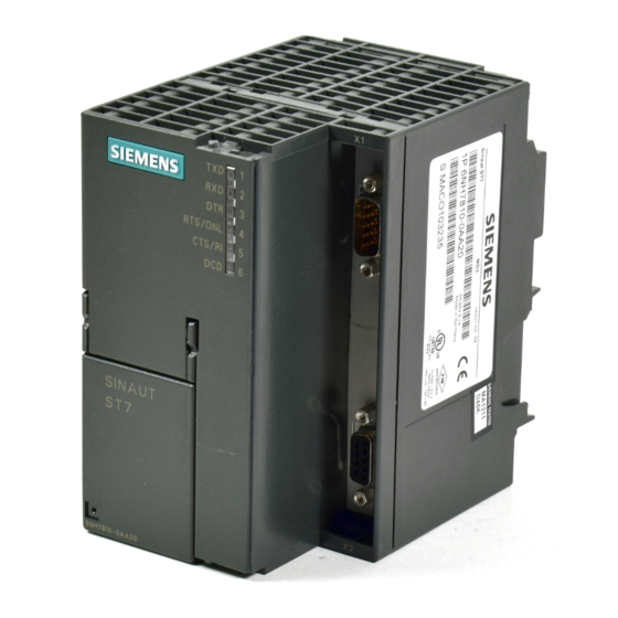
Article number, hardware revision level and MAC addresses are engraved on the enclosure. Figure 1 SIMATIC S7-300 with TIM 3V-IE Advanced (left) and TIM 4R-IE (right) The following communication modules of the SINAUT ST7 telecontrol system are not described in this system manual: ● TIM 1531 IRC ●... - Page 4 The SINAUT ST7 System Manual is divided into three volumes. ● Volume 1: System & Hardware Volume 1 introduces you to the SINAUT ST7 station control system and gives you an overview of the current hardware components. You will be supported during the planning of network structures and topologies and will see how to install and commission SINAUT components based on the installation guidelines.
- Page 5 – When using TD7onCPU, the SINAUT TD7 library for the V2.2 + SP4 + HF1 CPU must also be installed along with the SINAUT engineering software. You can find the description of the configuration in Volume 2 of the system manual. SINAUT ST7 - Volume 1 System Manual, 11/2018, C79000-G8976-C178-12...
- Page 6 Siemens’ products and solutions undergo continuous development to make them more secure. Siemens strongly recommends that product updates are applied as soon as they are available and that the latest product versions are used. Use of product versions that are no longer supported, and failure to apply the latest updates may increase customers’...
- Page 7 Read the product notifications about this on the Internet: Link: (https://support.industry.siemens.com/cs/ww/en/view/62607452) Documentation 09/2016 for TIM 4R / TIM 4RD and accessories This edition of the system manual no longer contains information on the TIM 4R and TIM 4RD modules. SINAUT ST7 - Volume 1 System Manual, 11/2018, C79000-G8976-C178-12...
- Page 8 Siemens contact. Keep to the local regulations. You will find information on returning the product on the Internet pages of Siemens Industry Online Support: Link: (https://support.industry.siemens.com/cs/ww/en/view/109479891)
- Page 9 A SINAUT-specific glossary can be found in the appendix of this manual. Training, Service & Support You will find information on training, service and support in the multilanguage document "DC_support_99.pdf" on the Internet pages of Siemens Industry Online Support: Link: (https://support.industry.siemens.com/cs/ww/en/view/38652101) Version history The previous versions of the manual described the innovations and versions listed below.
- Page 10 Validity of the manual: ● TIM 3V-IE, TIM 3V-IE Advanced, TIM 4R-IE, TIM 4R / 4RD ● SINAUT ST7 configuration and diagnostics software for the PG V5.4 ● SINAUT TD7 library for the CPU V2.2 SP2 ● SINAUT TIM firmware V4.4.0 for the TIM 4 ●...
- Page 11 Edition 09/2014 of the manual (C79000-G89xx-Cxxx-09) New functions: ● New version of the SINAUT ST7 configuration and diagnostics software V5.4 – Time-of-day synchronization of the TIM 4R-IE using NTP You will find the description in Volume 2 in section 3 (Configuration in STEP 7 >...
-
Page 12: System Manual, 11/2018, C79000-G8976-C178
Ethernet TIM to the Internet via a DSL modem. – The time slot method can now also be configured with the "SINAUT ST7 configuration software for the PG/PC" as of V5.0 for a master TIM without DCF7 receiver, if a TIM 4R-IE with an Ethernet connection to an ST7cc/ST7sc PC is used as the master TIM. - Page 13 Edition 10/2006 of the manual (C79000-G89xx-C178-05) New functions: ● New product versions – SINAUT ST7 configuration software for the PG/PC V4.0 – SINAUT TD7 library for the CPU V2.2 with new blocks for communication via P-bus ● New hardware for GSM and GPRS –...
- Page 14 Preface SINAUT ST7 - Volume 1 System Manual, 11/2018, C79000-G8976-C178-12...
-
Page 15: Table Of Contents
Table of contents Preface ..............................3 The SINAUT ST7 system ........................17 Area of application ........................17 Components in a SINAUT ST7 system .................. 18 1.2.1 Hardware components ......................18 1.2.2 Software components ......................21 Modules for new SINAUT projects and those to be expanded ..........22 Dedicated line and dial-up network modems ................ - Page 16 Technical specifications ........................101 Technical specifications of the TIM 3V-IE variants .............. 101 Technical specifications of the TIM 4R-IE ................107 Current consumption and power loss of the SINAUT ST7 components ......111 Interface allocation ....................... 113 Certifications and approvals ......................... 115 Accessories ............................
-
Page 17: The Sinaut St7 System
● SINAUT ST7cc, the PC control center (single or redundant) based on WinCC. This is a control center system for SINAUT ST7 specially tailored to the event-driven and time- stamped data transmission of the SINAUT system. -
Page 18: Components In A Sinaut St7 System
1.2 Components in a SINAUT ST7 system Local data storage One special characteristic of the TIM communications module used in the SINAUT ST7 system is the local storage of data (including time stamp) if there is a problem on the communication link, if a partner fails or to optimize costs on dial-up networks. - Page 19 The SINAUT ST7 system 1.2 Components in a SINAUT ST7 system ● GSM modem / mobile wireless Internet router – MODEM MD720 – Router SCALANCE M800 For details, see Appendix Accessories (Page 119). ● Connecting cables – Test cable for connecting two TIMS via RS-232 6NH7701-0AR –...
- Page 20 The SINAUT ST7 system 1.2 Components in a SINAUT ST7 system ● LTOP overvoltage protection modules – Overvoltage protection module 6NH9821-0BB00 – LTOP1 6NH9821-0BC11 – LTOP2 6NH9821-0BC12 ● Radio clock components – DCF7 antennas 6NH9831-0AA / -0BA / -0DA – Lightning protection for DCF7 antennas 6NH9831-2AA / -8LA ●...
-
Page 21: Software Components
● STEP 7 V5 - SINAUT Engineering Software SINAUT Engineering Software running under STEP 7 V5 contains: – SINAUT ST7 configuration and diagnostic software for the programming device – TD7onTIM: TD7 program blocks on the TIM (no memory required on the CPU) –... -
Page 22: Modules For New Sinaut Projects And Those To Be Expanded
STEP 7 Professional * STEP 7 V15.0: Firmware V1.0; STEP 7 V15.1: Firmware V2.0 Expansion of existing SINAUT ST7 projects in the TIA Portal SINAUT projects with TIM modules for the SIMATIC S7-300 and S7-400 series, which were configured in STEP 7 V5, can be extended with communications modules of the S7- 1200/1500 series which are configured in STEP 7 Basic or STEP 7 Professional in the TIA Portal. - Page 23 A TIM 4R-IE Stand-alone can only be created in new projects that are configured exclusively in STEP 7 Professional. You can find details on configuration in /1/ (Page 129). See system manual Volume 3. SINAUT ST7 - Volume 1 System Manual, 11/2018, C79000-G8976-C178-12...
-
Page 24: Dedicated Line And Dial-Up Network Modems
This is, of course, possible only when there is an adequately strong GSM signal at the relevant location. The latest SINAUT quadband mobile phone modem makes operation in the GSM networks available worldwide (850, 900, 1800 and 1900 MHz range). SINAUT ST7 - Volume 1 System Manual, 11/2018, C79000-G8976-C178-12... -
Page 25: Requirements For Gsm Mode
The SINAUT ST7 system 1.5 Mobile wireless modems and routers SINAUT ST7 provides two options for data transmission over mobile phone: ● MODEM MD720 – Data transmission on an "as necessary" basis by establishing a dial-up connection via a mobile network (CSD: Circuit Switched Data) Dial-up connections are charged on a pay-by-time basis. -
Page 26: Sinaut St7Cc, The Add-On For Wincc
Properties Telecontrol master with user-friendly diagnostics ● Direct connection of SINAUT ST7 TIMs to ST7cc over MPI and Ethernet. An upstream CPU as telecontrol master is not required. ● Availability of the most important status information of each SINAUT subscriber with visualization in WinCC using provided station typicals (picture typicals and faceplates) ●... - Page 27 The configuration of the entire system with ST7ccConfig is very user-friendly. Extra WinCC configuration for the tag management, and the archive and message system is restricted to a few preparations, such as creating message classes and types and archives in WinCC. SINAUT ST7 - Volume 1 System Manual, 11/2018, C79000-G8976-C178-12...
-
Page 28: Sinaut St7Sc Scada Connect Software
While ST7sc normally only creates one "memory cell" per item in which the latest status or value of the item is kept ready, with item buffering a buffer is created for each item in which SINAUT ST7 - Volume 1 System Manual, 11/2018, C79000-G8976-C178-12... - Page 29 ● It transfers data to be sent to the stations only once to one of the two ST7sc applications so that there is no duplicate transfer. Configuration ST7sc is configured using "ST7sc Config", which is included in the ST7sc software package. SINAUT ST7 - Volume 1 System Manual, 11/2018, C79000-G8976-C178-12...
- Page 30 The SINAUT ST7 system 1.7 SINAUT ST7sc SCADA Connect software SINAUT ST7 - Volume 1 System Manual, 11/2018, C79000-G8976-C178-12...
-
Page 31: Properties Of The Tim Modules
(Telecontrol Interface Module). This handles the data traffic for the S7-CPU or for the control center PC with the aid of the SINAUT ST7 protocol via the relevant SINAUT network. The TIM is housed in an S7-300 enclosure and is available in the following versions: TIM 3V-IE The TIM 3V-IE is a SINAUT communications module for the SIMATIC S7-300. -
Page 32: Communications Services
Overview: Connection to LAN / WAN (Page 36). The "SINAUT ST7" protocol For telecontrol communication via telecontrol networks the TIM uses the ST7 protocol on the application layer (OSI layer 7). SINAUT ST7 - Volume 1 System Manual, 11/2018, C79000-G8976-C178-12... - Page 33 ● Communication with the control center The TIM communicates via LAN or WAN with an application in the master station. You will find the supported master station types in the section The SINAUT ST7 system (Page 17). ● Direct communication In dial-up networks, mobile networks and Ethernet networks, there is direct communication between the subscribers.
-
Page 34: Security Functions
Key exchange interval. Further security functions of the TIM The TIM also supports the following security functions: ● NTP (secure) For secure transfer during time-of-day synchronization SINAUT ST7 - Volume 1 System Manual, 11/2018, C79000-G8976-C178-12... - Page 35 ● Log files To allow monitoring, events can be stored in log files that can be read out using STEP 7 Professional or can be sent automatically to a Syslog server. SINAUT ST7 - Volume 1 System Manual, 11/2018, C79000-G8976-C178-12...
-
Page 36: Overview: Connection To Lan / Wan
(modems, routers, switches). The table contains the information for the interfaces of the TIM and for the connection of the communication partner. The protocols or services used are listed. SINAUT ST7 - Volume 1 System Manual, 11/2018, C79000-G8976-C178-12... - Page 37 ● MODEM MD720 (Page 120) ● Connecting cables between TIM and modem: Connecting cables (Page 123) To connect a modem to the TIM a cable must be ordered. ● SCALANCE S: /8/ (Page 130) SINAUT ST7 - Volume 1 System Manual, 11/2018, C79000-G8976-C178-12...
-
Page 38: Tim 3V-Ie / Tim 3V-Ie Advanced
● With a TIM 3V-IE, an S7-300 CPU or a C7 control system can then handle SINAUT communication: – Via a classic SINAUT WAN with SINAUT partners – Over an IP-based network (WAN or LAN) with SINAUT ST7 subscribers ● It has two interfaces: – RS-232 interface for connection of required WAN transmission equipment (classic... - Page 39 ● Can be operated without a fan ● A backup battery or memory module are not required The following figure shows the connectors of the TIM 3V-IE or TIM 3V-IE Advanced (schematic representation with covers removed). SINAUT ST7 - Volume 1 System Manual, 11/2018, C79000-G8976-C178-12...
- Page 40 Front view of a TIM 3V-IE version with closed front door The hardware revision level of the device is printed as placeholder "X" (e.g. X 2 3 4). In this case, "X" would be the placeholder for hardware product version 1. SINAUT ST7 - Volume 1 System Manual, 11/2018, C79000-G8976-C178-12...
-
Page 41: Leds Of Tim 3V-Ie Versions
The following table summarizes the meaning of the nine LEDs during normal operation. For the LED pattern during the startup, refer to the section Startup of the TIM 3V-IE variants (Page 96). SINAUT ST7 - Volume 1 System Manual, 11/2018, C79000-G8976-C178-12... - Page 42 Dial-up network Receive data Lights up with an incoming call (RI), remains lit as long as receive level (DCD) is detected, and goes off while a telegram is being received (RXD). SINAUT ST7 - Volume 1 System Manual, 11/2018, C79000-G8976-C178-12...
-
Page 43: Tim 4R-Ie
● This allows these devices to handle SINAUT communication: – Over any two classic SINAUT WANs with SINAUT partners – Over two IP-based networks (WAN or LAN) with SINAUT ST7 subscribers ● All four interfaces can be used at the same time for SINAUT communication. - Page 44 I/O expansion cable. ● Can be operated without a fan ● A backup battery and a memory module (C-PLUG) can be installed as options. SINAUT ST7 - Volume 1 System Manual, 11/2018, C79000-G8976-C178-12...
- Page 45 Front view of the TIM 4R-IE with closed front panel The hardware revision level of the device is printed as placeholder "X" (e.g. X 2 3 4). In this case, "X" would be the placeholder for hardware product version 1. SINAUT ST7 - Volume 1 System Manual, 11/2018, C79000-G8976-C178-12...
-
Page 46: Leds Of Tim 4R-Ie
The following table summarizes the meaning of the LEDs during normal operation. For the LED pattern during the startup, refer to the section Startup activities of the TIM 4R-IE (Page 98). SINAUT ST7 - Volume 1 System Manual, 11/2018, C79000-G8976-C178-12... - Page 47 Dial-up network Receive data Lights up with an incoming call (RI), remains lit as long as receive level (DCD) is detected and goes off while a message is being received (RXD). SINAUT ST7 - Volume 1 System Manual, 11/2018, C79000-G8976-C178-12...
-
Page 48: Reset Button
Following the default startup, the TIM can be loaded again both over the MPI interface of the CPU and over its own Ethernet interface. The reset button can be used to force a default startup of the TIM. SINAUT ST7 - Volume 1 System Manual, 11/2018, C79000-G8976-C178-12... - Page 49 4. Wait until the startup of the TIM is completed and the default startup is signaled by the LEDs. For the relevant LED patterns see the following section: – Startup of the TIM 3V-IE variants (Page 96) – Startup activities of the TIM 4R-IE (Page 98) SINAUT ST7 - Volume 1 System Manual, 11/2018, C79000-G8976-C178-12...
- Page 50 MPI bus to be able to transfer the parameters (including the correct MPI address) to the TIM. For the "partyline", see Glossary (Page 131). 6. After loading the SDBs, restart the TIM. SINAUT ST7 - Volume 1 System Manual, 11/2018, C79000-G8976-C178-12...
-
Page 51: Network Structures, Configuration Examples, Installation Guidelines
The following overview shows you the network structures that can be implemented with SINAUT ST7 in a WAN and on Industrial Ethernet. For each network configuration, you will also see the protocols and modes with which SINAUT can handle communication over the network. -
Page 52: Configurations
• With redundant WAN connections, a TIM 4 or TIM 4R-IE with two interfaces must always be used because redundant paths always start and end on a TIM module. 3.2.1 Configurations with IP-based WAN IP-based network, linking via switches Figure 3-1 IP-based network, linking via switches SINAUT ST7 - Volume 1 System Manual, 11/2018, C79000-G8976-C178-12... - Page 53 Wireless Ethernet communication Figure 3-2 Wireless Ethernet communication Wireless Ethernet communication with TIM 3V-IE in master stations and stations Figure 3-3 Wireless Ethernet communication with TIM 3V-IE in master stations and stations SINAUT ST7 - Volume 1 System Manual, 11/2018, C79000-G8976-C178-12...
- Page 54 Network structures, configuration examples, installation guidelines 3.2 Configurations IP-based communication via DSL Figure 3-4 IP-based communication via DSL SINAUT ST7 - Volume 1 System Manual, 11/2018, C79000-G8976-C178-12...
- Page 55 Network structures, configuration examples, installation guidelines 3.2 Configurations IP-based communication via GPRS with simple security (simple Internet communication) Figure 3-5 IP-based communication (GPRS/DSL) with MSC protocol via MD720 modem SINAUT ST7 - Volume 1 System Manual, 11/2018, C79000-G8976-C178-12...
- Page 56 Network structures, configuration examples, installation guidelines 3.2 Configurations IP-based communication via GPRS with higher security Figure 3-6 GPRS with higher security via SCALANCE M874 router SINAUT ST7 - Volume 1 System Manual, 11/2018, C79000-G8976-C178-12...
-
Page 57: Configurations With Classic Wan
Network structures, configuration examples, installation guidelines 3.2 Configurations 3.2.2 Configurations with classic WAN Dedicated line configurations Figure 3-7 Dedicated line configurations SINAUT ST7 - Volume 1 System Manual, 11/2018, C79000-G8976-C178-12... - Page 58 Network structures, configuration examples, installation guidelines 3.2 Configurations Radio network configuration Figure 3-8 Radio network configurations SINAUT ST7 - Volume 1 System Manual, 11/2018, C79000-G8976-C178-12...
- Page 59 Network structures, configuration examples, installation guidelines 3.2 Configurations Dial-up network configuration Figure 3-9 Dial-up network configurations SINAUT ST7 - Volume 1 System Manual, 11/2018, C79000-G8976-C178-12...
- Page 60 3.2 Configurations Examples of redundant configurations Figure 3-10 Redundant configurations For further options for setting up redundant transmission paths, refer to section Installing the TIM 4R-IE in an S7-300 (Page 70). SINAUT ST7 - Volume 1 System Manual, 11/2018, C79000-G8976-C178-12...
-
Page 61: Installation Guidelines And Compatible Cpus
CPU 312 IFM 6ES7 312-5AC00-0AB0 6ES7 312-5AC02-0AB0 CPU 313 6ES7 313-1AD00-0AB0 6ES7 313-1AD01-0AB0 6ES7 313-1AD02-0AB0 6ES7 313-1AD03-0AB0 CPU 314 6ES7 314-1AE02-0AB0 6ES7 314-1AE03-0AB0 6ES7 314-1AE04-0AB0 6ES7 314-1AF10-0AB0 6ES7 314-1AF11-0AB0 6ES7 314-1AG13-0AB0 6ES7 314-1AG14-0AB0 SINAUT ST7 - Volume 1 System Manual, 11/2018, C79000-G8976-C178-12... - Page 62 6ES7 317-6FF03-0AB0 6ES7 317-6FF04-0AB0 CPU 317F-2 PN/DP 6ES7 317-2FJ10-0AB0 6ES7 317-2FK13-0AB0 6ES7 317-2FK14-0AB0 CPU 318-2 6ES7 318-2AJ00-0AB0 CPU 319-3 PN/DP 6ES7 318-3EL00-0AB0 6ES7 318-3EL01-0AB0 CPU 319F-3 PN/DP 6ES7 318-3FL00-0AB0 6ES7 318-3FL01-0AB0 SINAUT ST7 - Volume 1 System Manual, 11/2018, C79000-G8976-C178-12...
- Page 63 C7-613 6ES7 613-1CA00-0AE3 6ES7 613-1CA01-0AE3 6ES7 613-1CA02-0AE3 C7-621 6ES7 621-1AD02-0AE3 C7-623/P 6ES7 623-1DE00-0AE3 C7-626/P 6ES7 626-1DG02-0AB3 6ES7 626-1DG04-0AE3 C7-626/P DP 6ES7 626-2DG02-0AB3 6ES7 626-2DG03-0AE3 6ES7 626-2DG04-0AE3 C7-633/P 6ES7 633-1DF00-0AB3 6ES7 633-1DF02-0AE3 SINAUT ST7 - Volume 1 System Manual, 11/2018, C79000-G8976-C178-12...
- Page 64 S7-300 rail or on a 35 mm DIN rail (an adapter is available). To save space, it can also be installed in a free slot of racks 0 to 3. This modem is connected over the RS-232 interface of the TIM using a standard connecting cable, type 6NH7701-xxx. SINAUT ST7 - Volume 1 System Manual, 11/2018, C79000-G8976-C178-12...
- Page 65 SIMATIC S7-300 with TIM 3V-IE with 1 connection to classic WAN over an external modem. Other modems with an RS-232 interface can also be used, for example wireless devices or the MODEM MD720. SINAUT ST7 - Volume 1 System Manual, 11/2018, C79000-G8976-C178-12...
- Page 66 ● DSL router ● Backbone transmission systems such as OTN, PCM30 Two examples are illustrated below. Figure 3-13 SIMATIC S7-300 with TIM 3V-IE connected to an FO cable over a SCALANCE X-200 SINAUT ST7 - Volume 1 System Manual, 11/2018, C79000-G8976-C178-12...
- Page 67 CPU. This TD7 program runs either on the CPU (TD7onCPU) or on the TIM (TD7onTIM). SINAUT ST7 - Volume 1 System Manual, 11/2018, C79000-G8976-C178-12...
- Page 68 WAN. In this case, the maximum number of TIM modules is not restricted by the connection resources of the CPU because they are not required. The SINAUT ST7 - Volume 1 System Manual, 11/2018, C79000-G8976-C178-12...
- Page 69 TIM modules is not restricted by the connection resources of the CPU because they are not required. The maximum number of TIM modules is restricted by the number of connection resources of the CP in the control center PC. SINAUT ST7 - Volume 1 System Manual, 11/2018, C79000-G8976-C178-12...
-
Page 70: Installing The Tim 4R-Ie In An S7-300
6ES7 313-1AD01-0AB0 6ES7 313-1AD02-0AB0 6ES7 313-1AD03-0AB0 CPU 314 6ES7 314-1AE02-0AB0 6ES7 314-1AE03-0AB0 6ES7 314-1AE04-0AB0 6ES7 314-1AF10-0AB0 6ES7 314-1AF11-0AB0 6ES7 314-1AG13-0AB0 6ES7 314-1AG14-0AB0 CPU 314 IFM 6ES7 314-5AE02-0AB0 6ES7 314-5AE03-0AB0 6ES7 314-5AE10-0AB0 SINAUT ST7 - Volume 1 System Manual, 11/2018, C79000-G8976-C178-12... - Page 71 6ES7 317-6FF03-0AB0 6ES7 317-6FF04-0AB0 CPU 317F-2 PN/DP 6ES7 317-2FJ10-0AB0 6ES7 317-2FK13-0AB0 6ES7 317-2FK14-0AB0 CPU 318-2 6ES7 318-2AJ00-0AB0 CPU 319-3 PN/DP 6ES7 318-3EL00-0AB0 6ES7 318-3EL01-0AB0 CPU 319F-3 PN/DP 6ES7 318-3FL00-0AB0 6ES7 318-3FL01-0AB0 SINAUT ST7 - Volume 1 System Manual, 11/2018, C79000-G8976-C178-12...
- Page 72 C7-613 6ES7 613-1CA00-0AE3 6ES7 613-1CA01-0AE3 6ES7 613-1CA02-0AE3 C7-621 6ES7 621-1AD02-0AE3 C7-623/P 6ES7 623-1DE00-0AE3 C7-626/P 6ES7 626-1DG02-0AB3 6ES7 626-1DG04-0AE3 C7-626/P DP 6ES7 626-2DG02-0AB3 6ES7 626-2DG03-0AE3 6ES7 626-2DG04-0AE3 C7-633/P 6ES7 633-1DF00-0AB3 6ES7 633-1DF02-0AE3 SINAUT ST7 - Volume 1 System Manual, 11/2018, C79000-G8976-C178-12...
- Page 73 For all S7-300 racks the following applies: All slots designed for SM, FM or CP can also be used for the TIM. A bus module connector ships with every TIM. The TIM is connected to the module to its left by the bus module connector. SINAUT ST7 - Volume 1 System Manual, 11/2018, C79000-G8976-C178-12...
- Page 74 Ethernet interface connected over SCALANCE X-200 by FO cable Instead of the MDx SINAUT modem, other modems with an RS-232 or RS-485 interface can also be used, for example wireless devices or the MD720. SINAUT ST7 - Volume 1 System Manual, 11/2018, C79000-G8976-C178-12...
- Page 75 TIM and DSL router in order to establish a VPN tunnel to the MD741-1. A SCALANCE M874 router can be used instead of DSL router and SCALANCE S612 A. SINAUT ST7 - Volume 1 System Manual, 11/2018, C79000-G8976-C178-12...
- Page 76 TIMs. The first example shows the path of direct communication between stations connected to a standalone TIM 4R-IE and a TIM 3V-IE. The two TIMs are interconnected over Ethernet. SINAUT ST7 - Volume 1 System Manual, 11/2018, C79000-G8976-C178-12...
- Page 77 TIM 4R-IE is installed in an S7-300 so that it can communicate with the standalone TIM 4 over the MPI interface of the CPU. Within the S7-300, the direct communication path is via the backplane bus. SINAUT ST7 - Volume 1 System Manual, 11/2018, C79000-G8976-C178-12...
- Page 78 Within the S7-300, the direct communication path is via the backplane bus. In this example, this also applies to the data exchanged with the master station over the TIM 3/4 (see figure below). SINAUT ST7 - Volume 1 System Manual, 11/2018, C79000-G8976-C178-12...
-
Page 79: Standalone Tim 4R-Ie With An S7-400 Or Pc
In standalone mode, in other words, without an S7-300-CPU, the TIM 4R-IE is ideally suited as a SINAUT communications processor for an S7-400 or for the PC of the ST7cc or ST7sc control center. SINAUT ST7 - Volume 1 System Manual, 11/2018, C79000-G8976-C178-12... - Page 80 V6.0 6ES7 414-3FM07-0AB0 V7.0 CPU 414-4H 6ES7 414-4HJ00-0AB0 V3.1.4 6ES7 414-4HJ04-0AB0 V4.0.10 6ES7 414-4HM14-0AB0 V4.5.0 6ES7 414-4HR14-0AB0 V4.5.0 CPU 414-5H 6ES7 414-4HM06-0AB0 V6.0 CPU 416-1 6ES7 416-1XJ00-0AB0 6ES7 416-1XJ01-0AB0 6ES7 416-1XJ02-0AB0 SINAUT ST7 - Volume 1 System Manual, 11/2018, C79000-G8976-C178-12...
- Page 81 SINAUT MD2, MD3 or MD4 modems are used, they can also be installed on the same rail. The bus module connector supplied with every TIM is not required here since the TIM and modem are always interconnected over the 6NH7701-xxx connecting cable. SINAUT ST7 - Volume 1 System Manual, 11/2018, C79000-G8976-C178-12...
- Page 82 Ethernet card of the control center computer over one of its Ethernet ports. The following figure shows a configuration for a control center system SINAUT ST7cc or ST7sc with a TIM 4R-IE connected via Industrial Ethernet. SINAUT ST7 - Volume 1 System Manual, 11/2018, C79000-G8976-C178-12...
- Page 83 ST7cc / ST7sc and from the S7-400. The next figure shows a similar configuration. Here, a redundant SINAUT ST7cc or ST7sc control center system is connected over one of the Ethernet ports. SINAUT ST7 - Volume 1 System Manual, 11/2018, C79000-G8976-C178-12...
- Page 84 Redundant SINAUT ST7cc / ST7sc control center system with TIM 4R-IE connected over Ethernet, 1 connection to IP-based WAN or LAN, 2 classic connections to WAN, for example over SINAUT MDx modems SINAUT ST7 - Volume 1 System Manual, 11/2018, C79000-G8976-C178-12...
-
Page 85: Installation, Connecting Up, Commissioning
Coupling of extraneous voltages can be inductive or capacitive, for example due to the effects of lightning. Direct conductive coupling is also possible due to bad insulation. The overvoltage protection modules limit extraneous voltage and overvoltage to a non- critical level. SINAUT ST7 - Volume 1 System Manual, 11/2018, C79000-G8976-C178-12... -
Page 86: Notes On Use In Hazardous Areas
Replacing components may impair suitability for Class 1, Division 2 or Zone 2. WARNING The device may only be operated in an environment with pollution degree 1 or 2 (see IEC 60664-1). SINAUT ST7 - Volume 1 System Manual, 11/2018, C79000-G8976-C178-12... -
Page 87: Notes On Use In Hazardous Areas According To Atex / Iecex
Notes on use in hazardous areas according to ATEX / IECEx WARNING DIN rail In the ATEX and IECEx area of application only a Siemens DIN rail 6ES7590-1Axx0-0AB0 may be used to mount the TIM. WARNING Requirements for the cabinet To comply with EC Directive 2014/34 EU (ATEX) or the conditions of IECEx, this enclosure or cabinet must meet the requirements of at least IP54 in compliance with EN 60529. -
Page 88: Notes On Use In Hazardous Areas According To Ul Hazloc
This equipment is suitable for use in Class I, Zone 2, Group IIC or non-hazardous locations only. WARNING Substitution of components may impair suitability for Division 2. WARNING Substitution of components may impair suitability of the equipment. SINAUT ST7 - Volume 1 System Manual, 11/2018, C79000-G8976-C178-12... -
Page 89: Installation
Dimensions of the TIM Dimensions for installation The specifications for the installation dimensions of the components are required to design the mechanical structure of a SINAUT ST7 system. Table 4- 1 Dimensions for installation of the SINAUT ST7 components Module... -
Page 90: Mounting Position - Horizontal / Vertical Installation
• Above the TIM: At least 40 mm • Below the TIM: At least 40 mm Permitted ambient temperature The SINAUT ST7 components can be operated in the same temperature range specified for the S7-300. You can find the permitted temperature ranges in the section Technical specifications (Page 101). -
Page 91: Mounting Versions
TIM. 3. Place the TIM on the standard rail and push it in towards the bottom. 4. Screw the TIM securely into position. SINAUT ST7 - Volume 1 System Manual, 11/2018, C79000-G8976-C178-12... -
Page 92: Installing The Tim 4R-Ie As A Stand-Alone Device
The LED pattern of the TIM during startup differs from the one in productive operation. For the LED pattern during startup, refer to section Startup behavior of the TIM modules (Page 96). Then the configuration data (SDBs) must be loaded. SINAUT ST7 - Volume 1 System Manual, 11/2018, C79000-G8976-C178-12... -
Page 93: Connecting The Stand-Alone Tim 4R-Ie
The LED pattern of the TIM during startup differs from the one in productive operation. For the LED pattern during startup, refer to section Startup behavior of the TIM modules (Page 96). Then the configuration data (SDBs) must be loaded. SINAUT ST7 - Volume 1 System Manual, 11/2018, C79000-G8976-C178-12... -
Page 94: Connection Of The Md720 To The Tim And Antenna
The power for the device (24 V DC) must be generated as a safe extra low voltage. This means it must be a SELV (Safety Extra Low Voltage) or PELV (Protective Extra Low Voltage) according to DIN VDE 0100 Part 410 (IEC 60364-4-41). SINAUT ST7 - Volume 1 System Manual, 11/2018, C79000-G8976-C178-12... - Page 95 3. Close the front panels. Wiring diagram The figure below shows the wiring diagram for one or more TIM modules. Figure 4-2 Connecting TIM 3V-IE versions and TIM 4R-IE to the power supply SINAUT ST7 - Volume 1 System Manual, 11/2018, C79000-G8976-C178-12...
-
Page 96: Configuring And Downloading
The only exceptions are the LINK and RX/TX LEDs that have no significance during the startup of the TIM 3V-IE variants. SINAUT ST7 - Volume 1 System Manual, 11/2018, C79000-G8976-C178-12... - Page 97 (firmware does not match module type) 1) The LEDs KBus, TxD and RxD now operate in normal mode 2) The LEDs KBus, TxD and RxD remain in the phase in which the error occurred SINAUT ST7 - Volume 1 System Manual, 11/2018, C79000-G8976-C178-12...
-
Page 98: Startup Activities Of The Tim 4R-Ie
Loading the operating system from flash memory Starting VxWorks operating sys- Loading and starting TIM firmware Initializing flash file system and Flash- starting the start manager Loading and starting P bus driver Flash- SINAUT ST7 - Volume 1 System Manual, 11/2018, C79000-G8976-C178-12... - Page 99 TIM. In the section on the SINAUT Diagnostics and Service Tool in Volume 2 of the system manual, you can find all the error messages that cause the group error LED (SF) to light up. SINAUT ST7 - Volume 1 System Manual, 11/2018, C79000-G8976-C178-12...
- Page 100 Following the aborted startup, the LED pattern of the TIM appears as shown in row 13g of the table. Although the TIM 4R-IE can then be assessed for loading, it does not perform any further functions. SINAUT ST7 - Volume 1 System Manual, 11/2018, C79000-G8976-C178-12...
-
Page 101: Technical Specifications
With wire end ferrule 0.25 .. 1.5 mm / AWG 24 .. 16 • • With TWIN wire end ferrule 0.5 .. 1.0 mm / AWG 20 .. 17 • • SINAUT ST7 - Volume 1 System Manual, 11/2018, C79000-G8976-C178-12... - Page 102 Max. 1 (only as MSC station) • • PG communication Max. 2 • • Communication via Ethernet interface Protocol TCP/IP transport protocol Communication services SINAUT ST7 using S7 communication • PG communication • SINAUT ST7 - Volume 1 System Manual, 11/2018, C79000-G8976-C178-12...
- Page 103 5.1 Technical specifications of the TIM 3V-IE variants Technical specifications - TIM 3V-IE Communication via serial interface Selectable protocols SINAUT ST7 • SINAUT ST1 • Communications services SINAUT ST7 via MSC tunnel • PG communication • Mode with dedicated line/wireless With SINAUT ST7 protocol Polling • network Polling with time slots •...
- Page 104 Maximum cable length Power supply Design 2-pin plug-in terminal strip Power supply Type of voltage 24 VDC • • Permitted low limit 20.4 V • • Permitted high limit 28.8 V • • SINAUT ST7 - Volume 1 System Manual, 11/2018, C79000-G8976-C178-12...
- Page 105 Max. 24 • • pending on the interface used: MSC connections Max. 1 (only as MSC station) • • Total number of simultaneously op- Max. 25 erable productive connections (S7 + MSC) SINAUT ST7 - Volume 1 System Manual, 11/2018, C79000-G8976-C178-12...
- Page 106 Technical specifications - TIM 3V-IE Advanced PG communication Max. 4 • • Communication via Ethernet interface Protocol TCP/IP transport protocol Communication services SINAUT ST7 using S7 communication • PG communication • Communication via serial interface Selectable protocols SINAUT ST7 • SINAUT ST1 •...
-
Page 107: Technical Specifications Of The Tim 4R-Ie
Max. 100 m IE FC TP Standard Cable with IE FC RJ45 Plug 180 • Max. 90 m IE FC TP Standard Cable + 10 m TP Cord via IE FC RJ45 Outlet • SINAUT ST7 - Volume 1 System Manual, 11/2018, C79000-G8976-C178-12... - Page 108 During operation with the rack in- 0 °C ... +60 °C stalled horizontally During operation with the rack in- 0 °C ... +40 °C stalled vertically During storage -40 ℃ to +70 ℃ SINAUT ST7 - Volume 1 System Manual, 11/2018, C79000-G8976-C178-12...
- Page 109 PG communication Max. 2 • • Communication via Ethernet interface Protocol TCP/IP transport protocol Communication services SINAUT ST7 using S7 communication • SINAUT ST7 via MSC tunnel • PG communication • Communication via serial interface (RS-232 / RS-485) Selectable protocols SINAUT ST7 •...
- Page 110 On MMC of the S7-300 CPU • Work memory required on the S7 TD7onCPU At least 20 KB; actual requirements depend on the amounts of data and scope of func- tions TD7onTIM Best case, 0 bytes SINAUT ST7 - Volume 1 System Manual, 11/2018, C79000-G8976-C178-12...
-
Page 111: 5.3 Current Consumption And Power Loss Of The Sinaut St7 Components
Current consumption and power loss of the SINAUT ST7 components Introduction The SINAUT ST7 components obtain the current required for operation from an external power supply. When a TIM is installed in an S7-300, it also consumes electricity via the S7- 300 backplane bus. - Page 112 Technical specifications 5.3 Current consumption and power loss of the SINAUT ST7 components ● 2 digital input modules SM 321; DI 16 x DC 24 V ● 1 relay module SM 322; DO 8 x AC 230 V/5 A ● 1 analog input module SM 331; AI 8 x 12 bits ●...
-
Page 113: Interface Allocation
Pin assignment of the plug of the serial interface Illustration Pin no. Signal name Signal direction With TIM 4R-IE Input Input Switchover to RS-485 by configuration Output Switchover to RS-485 by configuration Output Output Input SINAUT ST7 - Volume 1 System Manual, 11/2018, C79000-G8976-C178-12... - Page 114 The Ethernet interfaces are designed as 8-pin RJ45 sockets. Table 5- 4 Pin assignment of the RJ45 socket of the Ethernet interface Illustration Pin no. Signal name Signal direction TXD+ Output TXD- Output RXD+ Input RXD- Input SINAUT ST7 - Volume 1 System Manual, 11/2018, C79000-G8976-C178-12...
-
Page 115: Certifications And Approvals
EC L174, 01/07/2011, page 88-110 The EC Declaration of Conformity is available for all responsible authorities at: Siemens Aktiengesellschaft Division Process Industries and Drives Process Automation DE-76181 Karlsruhe Germany SINAUT ST7 - Volume 1 System Manual, 11/2018, C79000-G8976-C178-12... - Page 116 Applied standards: – EN 60079-0 - Explosive atmospheres - Part 0: Equipment - General requirements – EN 60079-15 - Explosive atmospheres - Part 15: Equipment protection by type of protection 'n' SINAUT ST7 - Volume 1 System Manual, 11/2018, C79000-G8976-C178-12...
- Page 117 ● IEC/UL 61010-2-201 (Safety requirements for electrical equipment for measurement, control and laboratory use. Particular requirements for control equipment) ● Canadian Standards Association: CSA C22.2 No. 142 (Process Control Equipment) Certificate Number: NRAQ7.E85972 SINAUT ST7 - Volume 1 System Manual, 11/2018, C79000-G8976-C178-12...
- Page 118 SIMATIC NET products are regularly submitted to the relevant authorities and approval centers for approvals relating to specific markets and applications. If you require a list of the current approvals for individual devices, consult your Siemens contact or get the information on the Internet.
-
Page 119: Accessories
3G router for wireless IP communication via 3G mobile phone HSPA+, VPN, firewall, NAT, 1 RJ45 Ethernet interface with 2-port switch, SMA antenna connector, 1 digital input, 1 digital output Article number: 6GK5874-3AA00-2AA2 SINAUT ST7 - Volume 1 System Manual, 11/2018, C79000-G8976-C178-12... -
Page 120: Modem Md720
1 digital input, 1 digital output – Version for Europe Article number: 6GK5876-4AA00-2BA2 – Version for North America Article number: 6GK5876-4AA00-2DA2 Information on the devices can be found on the Internet pages of Siemens Industry Online Support: Link: (https://support.industry.siemens.com/cs/ww/en/ps/15982) MODEM MD720 MODEM MD720... -
Page 121: Mobile Wireless Antennas
Text mode Mobile wireless antennas GSM/GPRS antennas The following antennas are available for use in GSM/GPRS networks and can be installed both indoors and outdoors. The antennas must be ordered separately. SINAUT ST7 - Volume 1 System Manual, 11/2018, C79000-G8976-C178-12... - Page 122 Accessories A.3 Mobile wireless antennas Quadband antenna ANT794-4MR You will find detailed information in the device manual. You will find this on the Internet on the pages of Siemens Industry Online Support: Link: (https://support.industry.siemens.com/cs/ww/en/view/23119005) Figure A-1 ANT794-4MR GSM/GPRS antenna Short name...
-
Page 123: Dedicated Line And Dialup Network Modems
Connecting cables A series of standard connecting cables is available to connect individual SINAUT components with each other and to WANs. The following connecting cables can be ordered as required. SINAUT ST7 - Volume 1 System Manual, 11/2018, C79000-G8976-C178-12... - Page 124 Cable for connecting two TIMs via their RS-232 interface without modems (null modem). Cable length 6 m 6NH7701-4AL Cable for connecting a TIM (RS-232) to a SINAUT ST7 MDx modem (RS-232). Cable length 1.5 m 6NH7701-4BN Cable with one end without connector for connection of a TIM to a third-party modem or wireless device (RS-232).
- Page 125 Accessories A.5 Connecting cables Figure A-4 Assembly of the standard connecting cable 6NH7701-4AL Figure A-5 Assembly of the standard connecting cable 6NH7701-4BN Figure A-6 Assembly of the standard connecting cable 6NH7701-5AN SINAUT ST7 - Volume 1 System Manual, 11/2018, C79000-G8976-C178-12...
-
Page 126: Accessories For Rs-485 Connection
Connector assignment in RS-485 operation Observe the connector assignment specified by the modem manufacturer. When the serial interface is connected to a Siemens modem MDx in RS-485 operation, the following assignment applies: Figure A-7 Assignment of the RS-485 interfaces of the TIM 1531 IRC and an MDx modem... -
Page 127: Ethernet Cables
The following C-PLUGs are available: ● C-PLUG 32 Article number: 6GK1 900-0AB00 Memory: – Total capacity: 32 MB – Free capacity available: 30 MB Number of write cycles: Max. approx. 100000 SINAUT ST7 - Volume 1 System Manual, 11/2018, C79000-G8976-C178-12... - Page 128 Number of write cycles: Max. approx. 200000 Recommendation: Avoid writing data cyclically. The flash area allows a limited number of write cycles. You can find additional details in the Siemens Industry Mall: Link: (https://mall.industry.siemens.com) SINAUT ST7 - Volume 1 System Manual, 11/2018, C79000-G8976-C178-12...
-
Page 129: References
References Where to find Siemens documentation ● Article numbers You will find the article numbers for the Siemens products of relevance here in the following catalogs: – SIMATIC NET - Industrial Communication / Industrial Identification, catalog IK PI – SIMATIC - Products for Totally Integrated Automation and Micro Automation, catalog... - Page 130 Link: (https://support.industry.siemens.com/cs/ww/en/ps/15929/man) SIMATIC NET Industrial Ethernet Security Security basics and applications Configuration manual Siemens AG Link: (https://support.industry.siemens.com/cs/ww/en/ps/15326/man) SIMATIC NET Industrial Ethernet Security SCALANCE S Commissioning and Installation Manual Siemens AG Link: (https://support.industry.siemens.com/cs/ww/en/ps/15327/man) SINAUT ST7 - Volume 1 System Manual, 11/2018, C79000-G8976-C178-12...
-
Page 131: Glossary
Spontaneous / conditional spontaneous / unconditional spontaneous frame → Communications processor Module for expanded communications tasks that provides the CPU with additional interface types or communications options. Central Processing Unit Main processor of a SIMATIC controller SINAUT ST7 - Volume 1 System Manual, 11/2018, C79000-G8976-C178-12... - Page 132 See also "Inter-station communication" Context: Telecontrol / SINAUT Distributed Network Protocol Digital Subscriber Line Standards for transmission of telephone and Internet data with transmission speeds up to 1000 Mbps. EGPRS Enhanced GPRS SINAUT ST7 - Volume 1 System Manual, 11/2018, C79000-G8976-C178-12...
- Page 133 Each data frame is saved exactly one time in the image memory. New values of a data point overwrite the existing value in the image memory. See also send buffer Context: TeleControl SINAUT ST7 - Volume 1 System Manual, 11/2018, C79000-G8976-C178-12...
- Page 134 J/L/P services. The data of various services can be transferred simultaneously. Telephone connections normally operate at transmission speeds of 56 to 64 Kbps. Local Area Network Local network, usually "Industrial Ethernet". SINAUT ST7 - Volume 1 System Manual, 11/2018, C79000-G8976-C178-12...
- Page 135 MNC - Mobile Network Code PLMN → Multi Point Interface MPI is the programming device interface of the SIMATIC S7-300/400. Devices such as the TIM can communicate with each other via the MPI interface. SINAUT ST7 - Volume 1 System Manual, 11/2018, C79000-G8976-C178-12...
- Page 136 See also Partyline. The MSC transmission protocol is a proprietary protocol on OSI layer 3 for the secure communication via Ethernet, landline or mobile wireless networks in SINAUT ST7. The MSC protocol provides an authentication mechanism and simple encryption of data.
- Page 137 Polled data frames are data frames of a station or node TIM with a special identifier indicating that they were sent in response to a general request from the master station. Polling Polling mode → SINAUT ST7 - Volume 1 System Manual, 11/2018, C79000-G8976-C178-12...
- Page 138 The connection is multipoint-compliant; in other words, up to 32 subscribers can be connected. Request to send Signal in the data flow control SINAUT ST7 - Volume 1 System Manual, 11/2018, C79000-G8976-C178-12...
- Page 139 The SIM card is an identification card for a subscriber of a mobile wireless service. Simple Internet communication In SINAUT ST7, simple Internet communication means data exchange between TCP/IP- compliant devices in Ethernet, landline or mobile networks using the MSC protocol.
- Page 140 (SMSC) using a store-and-forward technique. They are buffered there and then forwarded to the recipient. The sender can query the status of the message in the SMS center or can request acknowledgment of delivery. SINAUT ST7 - Volume 1 System Manual, 11/2018, C79000-G8976-C178-12...
- Page 141 IP-based networks. For transmission in a dial-up network and in IP-based networks (for example GPRS), the data to be sent is assigned different priorities during configuration ("high" / "normal"). SINAUT ST7 - Volume 1 System Manual, 11/2018, C79000-G8976-C178-12...
- Page 142 SINAUT TD7 Library → Telecontrol Interface Module Communications module that handles all data transmission functions provided by the SINAUT system independently. Unconditional spontaneous frame Spontaneous / conditional spontaneous / unconditional spontaneous frame → SINAUT ST7 - Volume 1 System Manual, 11/2018, C79000-G8976-C178-12...
- Page 143 Internet using services such as DSL, GPRS, UMTS or LTE or via broadband systems such as OTN and PCM30. An IP-based WAN is normally connected to an RJ45 interface of a module via an Ethernet-capable module. SINAUT ST7 - Volume 1 System Manual, 11/2018, C79000-G8976-C178-12...
- Page 144 Glossary SINAUT ST7 - Volume 1 System Manual, 11/2018, C79000-G8976-C178-12...
-
Page 145: Index
Encryption, 34 Spare parts, 19 STEP 7 - version, 5 Firewall, 35 Firmwareversions, 3 Terminating resistor, 93, 94 Training, 9 Glossary, 8 VPN, 35 Inter-station communication, 33 IPsec, 35 MSC, 34 SINAUT ST7 - Volume 1 System Manual, 11/2018, C79000-G8976-C178-12... - Page 146 Index SINAUT ST7 - Volume 1 System Manual, 11/2018, C79000-G8976-C178-12...
Need help?
Do you have a question about the SINAUT ST7 and is the answer not in the manual?
Questions and answers