Table of Contents
Advertisement
Advertisement
Table of Contents

Related Manuals for Supermicro X10DSC+


Summary of Contents for Supermicro X10DSC+
- Page 1 X10DSC+ USER’S MANUAL Revision 1.0a...
- Page 2 This product, including software and docu- mentation, is the property of Supermicro and/or its licensors and is supplied only under a license. Any use or reproduction of this product is not allowed, except as expressly permitted by the terms of said license.
-
Page 3: About This Motherboard
RAID configuration, and SIOM networking option support. This motherboard is ideal for database storage and virtualization server platforms. Please refer to our website (http://www.supermicro.com) for CPU and memory support updates. Manual Organization Chapter 1 describes the features, specifications, and performance of the mother- board. -
Page 4: Conventions Used In The Manual
X10DSC+ Motherboard User’s Manual Conventions Used in the Manual Pay special attention to the following symbols for proper system installation: Warning: Important information given to ensure proper system installation or to prevent damage to the components or injury to yourself; Note: Additional information given to differentiate between models or instructions provided for proper system setup. -
Page 5: Contacting Supermicro
Super Micro Computer, Inc. 980 Rock Ave. San Jose, CA 95131 U.S.A. Tel: +1 (408) 503-8000 Fax: +1 (408) 503-8008 Email: marketing@supermicro.com (General Information) support@supermicro.com (Technical Support) Website: www.supermicro.com Europe Address: Super Micro Computer B.V. Het Sterrenbeeld 28, 5215 ML... -
Page 6: Table Of Contents
ACPI Features ....................1-13 Power Supply ....................1-13 Advanced Power Management ..............1-14 Intel Intelligent Power Node Manager (NM) (Available when the Supermicro ® Power Manager [SPM] is installed)............... 1-14 Management Engine (ME) ................1-14 Introduction to the AOM-S3108M-H8L Mezzanine Card (Optional) ..... 1-15 Introduction to the AOC-MTG-i4S SIOM Card (Optional) ...... - Page 7 Table of Contents Power LED ....................2-24 HDD LED/Front UID Switch ..............2-25 NIC1 & NIC2 LED Indicators..............2-25 Overheat (OH)/Fan Fail/PWR Fail/UID LED ..........2-26 Power Fail LED ..................2-26 Reset Button ................... 2-27 Power Button ................... 2-27 Connecting Cables ..................2-28 Power Connectors ...................
- Page 8 X10DSC+ Motherboard User’s Manual Battery Removal and Installation ..............3-6 Frequently Asked Questions ................3-7 Returning Merchandise for Service..............3-8 Chapter 4 BIOS Introduction ...................... 4-1 Main Setup ...................... 4-2 Advanced Setup Configurations..............4-4 Event Logs ....................4-30 IPMI .......................4-32 Security Settings ................... 4-34 Boot Settings ....................
-
Page 9: Chapter 1 Overview
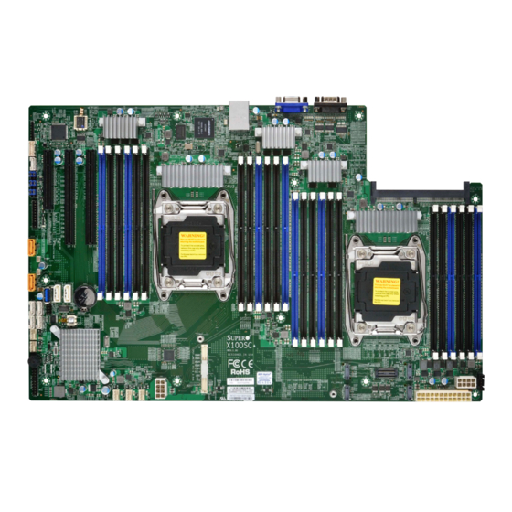
Overview Congratulations on purchasing your computer motherboard from an acknowledged leader in the industry. Supermicro boards are designed with the utmost attention to detail to provide you with the highest standards in quality and performance. This motherboard was designed to be used with a Supermicro-proprietary chassis as an integrated server platform. - Page 10 X10DSC+ Motherboard User’s Manual Motherboard Image Note: All graphics shown in this manual were based upon the latest PCB revision available at the time of publication of the manual. The mother- board you received may or may not look exactly the same as the graphics shown in this manual.
-
Page 11: Motherboard Layout
PCI-E 3.0 CPU2 HDD_LED1 LED2 CPU1 JSD2 JSD1 JBAT1 BIOS Battery S-SGPIO1 X10DSC+ REV:1.01 JITP1 JPW2 BIOS JPW3 IPMI CODE CPU-XDP LICENSE JPW1 BAR CODE JTPM1 Note: For the latest CPU/Memory updates, please refer to our website at http://www.supermicro.com/products/motherboard/ for details. - Page 12 X10DSC+ Motherboard User’s Manual X10DSC+ Quick Reference COM1 USB0/1(3.0) LED1 IPMI_LAN CPU2_MEMORY_LED CPU1_MEMORY_LED BMC_HB_LED1 CPU1 SIOM PCI-E 3.0 CPU2 HDD_LED1 LED2 CPU1 JSD2 JSD1 JBAT1 BIOS Battery S-SGPIO1 X10DSC+ REV:1.01 JITP1 JPW2 BIOS JPW3 IPMI CODE CPU-XDP LICENSE JPW1 BAR CODE JTPM1 Notes: •...
- Page 13 Chapter 1: Overview X10DSC+ Jumpers Jumper Description Default Setting JBT1 Clear CMOS/Reset BIOS Configuration See Chapter 2 JPB1 BMC Enable Pins 1-2 (Enabled) JPG1 VGA Enable Pins 1-2 (Enabled) JPME2 Manufacture (ME) Mode Select Pins 1-2 (Normal) JWD1 Watch Dog Timer Enable Pins 1-2 (Reset) X10DSC+ Connectors Connectors...
- Page 14 X10DSC+ Motherboard User’s Manual (BP) USB 0/1 (3.0) Backpanel USB 3.0 ports 0/1 USB 2 (3.0) Type A USB 3.0 connection header for front access (USB 2) Backpanel VGA port X10DSC+ Onboard LED Indicators Description State Status BMC_HB_LED1 BMC Heartbeat LED Green: Blinking BMC Normal HDD_LED1...
-
Page 15: Motherboard Features
Chapter 1: Overview Motherboard Features • Dual Intel® E5-2600v3/v4 Series processors (Socket R3-LGA 2011); each processor supports dual full- width Intel QuickPath Interconnect (QPI) links (of up to 9.6 GT/s one direction per QPI) Note 1: Both CPUs need to be installed for full access to the PCI-E slots, DIMM slots, and onboard controllers. -
Page 16: Peripheral Devices
• Power-on mode for AC power recovery • Intel® Intelligent Power Node Manager 3.0 (avail- able when the Supermicro Power Manager [SPM] is installed and a special power supply is used. See the note on Page 1-14.) • Management Engine (ME) - Page 17 CPU TDP sizing. Note 2: For IPMI configuration instructions, please refer to the Embedded IPMI Configuration User's Guide available at http://www.supermicro.com/ support/manuals/. Note 3: It is strongly recommended that you change BMC log-in informa- tion upon initial system power-on.
-
Page 18: System Block Diagram
X10DSC+ Motherboard User’s Manual X10DSC+ Block Diagram NCSI DDR3 DDR3 NCSI AST2400 IPMI LAN RTL8211E 32MB BMC UART COM1 SPI Flash SPI USB 16MB BMC SPI Flash SPI USB 2.0 [6/7] PE[3] TPM Header 8~11 SATA Gen3 [2/3] SATA_DOM1 SATA_DOM2 12~15 SATA Gen3 [0/1] port 3... -
Page 19: Processor And Chipset Overview
Chapter 1: Overview Processor and Chipset Overview Built upon the functionality and capability of the Intel E5-2600v3/v4 Series proces- sors (Socket R3) and the Intel C612 PCH, the X10DSC+ motherboard provides system performance, power efficiency, and feature sets to address the needs of next-generation computer users. -
Page 20: Special Features
X10DSC+ Motherboard User’s Manual Special Features Recovery from AC Power Loss The Basic I/O System (BIOS) provides a setting that determines how the system will respond when AC power is lost and then restored to the system. You can choose for the system to remain powered off (in which case you must press the power switch to turn it back on) or for it to automatically return to the power-on state. -
Page 21: Acpi Features
Chapter 1: Overview ACPI Features ACPI stands for Advanced Configuration and Power Interface. The ACPI specifi- cation defines a flexible and abstract hardware interface that provides a standard way to integrate power management features throughout a system, including its hardware, operating system, and application software. This enables the system to automatically turn on and off peripherals such as network cards, hard-disk drives, and printers. -
Page 22: Advanced Power Management
Intel Intelligent Power Node Manager (NM) (Available ® when the Supermicro Power Manager [SPM] is installed) The Intel Intelligent Power Node Manager 3.0 (IPNM) provides your system with ® real-time thermal control and power management for maximum energy efficiency. -
Page 23: Introduction To The Aom-S3108M-H8L Mezzanine Card (Optional)
This mezzanine card can directly support eight SSD devices and delivers SAS data transfer rates of up to 12Gb/s. Designed for use on a Supermicro propri- etary motherboard, the AOM-S3108M-H8L also supports CacheVault Flash Cache, MegaRAID, and can run on Windows and Linux operating systems. -
Page 24: Introduction To The Aoc-Mtg-I4S Siom Card (Optional)
Introduction to the AOC-MTG-i4S SIOM Card (Optional) The Supermicro AOC-MTG-i4S is the most advanced, intelligent SFP+ SIOM (Su- per I/O Module) card on the market today. This card supports Intel® XL710-AM1 LAN controller, quad SFP+ connectors (with a speed of up to 10 Gbps per port), Time Sync (IEEE 1588), Intel®... -
Page 25: Chapter 2 Installation
The following statements are industry-standard warnings, provided to warn the user of situations which might result in bodily injury. Should you have any questions or experience difficulty, contact Supermicro's Technical Support Department for as- sistance. Only certified technicians should attempt to install/change components or configure system settings. - Page 26 X10DSC+ Motherboard User’s Manual Attention Danger d'explosion si la pile n'est pas remplacée correctement. Ne la remplacer que par une pile de type semblable ou équivalent, recommandée par le fabricant. Jeter les piles usagées conformément aux instructions du fabricant. ¡Advertencia! Existe peligro de explosión si la batería se reemplaza de manera incorrecta.
-
Page 27: Product Disposal
Chapter 2: Installation Product Disposal Warning! Ultimate disposal of this product should be handled according to all national laws and regulations. 製品の廃棄 この製品を廃棄処分する場合、 国の関係する全ての法律 ・ 条例に従い処理する必要が あります。 警告 本产品的废弃处理应根据所有国家的法律和规章进行。 警告 本產品的廢棄處理應根據所有國家的法律和規章進行。 Warnung Die Entsorgung dieses Produkts sollte gemäß allen Bestimmungen und Gesetzen des Landes erfolgen. -
Page 28: Static-Sensitive Devices
X10DSC+ Motherboard User’s Manual القىانين واللىائح الىطنية جميع وفقا ل ينبغي التعامل معه هذا المنتج من التخلص النهائي عند 경고! 이 제품은 해당 국가의 관련 법규 및 규정에 따라 폐기되어야 합니다. Waarschuwing De uiteindelijke verwijdering van dit product dient te geschieden in overeenstemming met alle nationale wetten en reglementen. -
Page 29: Motherboard Installation
Chapter 2: Installation Motherboard Installation All motherboards have standard mounting holes to fit different types of chassis. Make sure that the locations of all mounting holes for both motherboard and chassis match. Although a chassis may have both plastic and metal mounting fasteners, metal ones are recommended because they ground the motherboard to the chas- sis. -
Page 30: Installing The Motherboard
X10DSC+ Motherboard User’s Manual Installing the Motherboard Note: Always connect the power cord last, and always remove it before adding, removing, or changing any hardware components. 1. Locate the mounting holes on the motherboard. X10DSC+ REV:1.01 2. Locate the matching mounting holes on the chassis. Align the mounting holes on the motherboard against the mounting holes on the chassis. -
Page 31: Processor And Heatsink Installation
CPU socket cap is in place and that none of the socket pins are bent; otherwise, contact your retailer immediately. Refer to the Supermicro website for updates on CPU support. Installing the LGA2011 Processor 1. There are two load levers on the LGA2011 socket. To open the socket cover, first press and release the load lever labeled "Open 1st."... - Page 32 X10DSC+ Motherboard User’s Manual 2. Press the second load lever labeled "Close 1st" to release the load plate that covers the CPU socket from its locking position. Press down on load Pull lever away from lever "Close 1st" socket 3. With the lever labeled "Close 1st" fully retracted, gently push down on the lever labeled "Open 1st"...
- Page 33 Chapter 2: Installation 4. Use your thumb and index finger to loosen the lever and open the load plate. 5. Using your thumb and index finger, hold the CPU by its edges. Align the CPU keys, which are semicircle notches, against the socket keys. Socket Keys CPU Keys 6.
- Page 34 X10DSC+ Motherboard User’s Manual 7. With the CPU inside the socket, inspect the four corners of the CPU to make sure that the CPU is properly installed. Gently close Push down and lock the the load plate lever labeled "Close 1st" 8.
-
Page 35: Installing A Passive Cpu Heatsink
Chapter 2: Installation Installing a Passive CPU Heatsink 1. Do not apply any thermal grease to the heatsink or the CPU die -- the re- quired amount has already been applied. 2. Place the heatsink on top of the CPU so that the four mounting holes are aligned with those on the motherboard and the heatsink bracket underneath. -
Page 36: Removing The Cpu And The Heatsink
X10DSC+ Motherboard User’s Manual Removing the CPU and the Heatsink Warning: We do not recommend that the CPU or the heatsink be removed. However, if you do need to uninstall the CPU or the heatsink, please follow the instructions below to uninstall the heatsink to avoid damaging the CPU or the motherboard. -
Page 37: Installing And Removing The Memory Modules
Chapter 2: Installation Installing and Removing the Memory Modules Note: Check Supermicro's website for a list of recommended memory modules. CAUTION Exercise extreme care when installing or removing DIMM modules to avoid damaging the DIMM modules or the motherboard. Installing & Removing DIMMs 1. - Page 38 (max.) in 24 slots. Memory speed support depends on the CPUs installed in the motherboard. For the latest memory updates, please refer to our website at http:// www.supermicro.com/products/motherboard. Processor & Memory Module Population Configuration For the memory to work properly, follow the tables below for memory installation.
- Page 39 Chapter 2: Installation Populating RDIMM/LRDIMM DDR4 Memory Modules for the E5- 2600v3-based Motherboard Speed (MT/s) Voltage (V) Speed (MT/s); Voltage (V); Slot Per Channel (SPC) and DIMM Per Channel (DPC) DIMM Capacity Ranks Per 1 Slot Per (GB) DIMM and 2 Slots Per Channel 3 Slots Per Channel Type...
-
Page 40: Mezzanine Card Installation (Optional)
X10DSC+ Motherboard User’s Manual Mezzanine Card Installation (Optional) For SAS 3.0 support, be sure to follow the instructions below to install the mezzanine card on the CPU JMEZZ1-PCI-E 3.0 located on the motherboard. Image of the Mezzanine Card 1. After installing the motherboard in the chassis, align the mezzanine card with the AOM PCI-E 3.0 slot (J35) on the motherboard. - Page 41 Chapter 2: Installation 3. With the mezzanine card securely placed in the slot, insert Pan Head #6 screws into the three standoff holes and tighten them with a Phillips screw- driver. Screw #2 Screw #1 Screw #3 2-17...
-
Page 42: Control Panel Connectors And I/O Ports
X10DSC+ Motherboard User’s Manual Control Panel Connectors and I/O Ports The I/O ports are color-coded in conformance with the industry standards. See the picture below for the colors and locations of the various I/O ports. Back Panel Connectors and I/O Ports COM1 USB0/1(3.0) LED1... -
Page 43: Serial Port
Chapter 2: Installation Serial Port One COM connection (COM1) is located on the I/O back panel on the motherboard. Refer to the board layout below for the location. Video Connection A Video (VGA) port is located next to COM Port 1 on the I/O back panel. Refer to the board layout below for the location. -
Page 44: Universal Serial Bus (Usb)
X10DSC+ Motherboard User’s Manual Universal Serial Bus (USB) Back Panel USB 0/1 (3.0) Type A USB 2 (3.0) Two USB 3.0 ports (USB 0/1) are located Pin Definitions on the I/O backpanel. In addition, a Pin# Description Type A USB connector (USB 2), located VBUS close to the onboard battery, also pro- SSRX-... -
Page 45: Ipmi-Dedicated Lan Port
Chapter 2: Installation IPMI-Dedicated LAN Port An IPMI-dedicated LAN, supported by the ASpeed AST2400 Baseboard Controller (BMC), is located above the USB 0/1 ports on the I/O backpanel. Connect a RJ45 cable here for IPMI LAN support. Please refer to the LED Indicator section for LAN LED information. -
Page 46: Unit Identifier Switches/Uid Led Indicators
X10DSC+ Motherboard User’s Manual Unit Identifier Switches/UID LED UID Switch Indicators Pin# Definition A rear Unit Identifier (UID) switch (JUIDB2) Ground and a rear UID LED (LED1) are located next Ground to the USB ports on the motherboard. A front Button In UID switch and its UID LED are both located Ground... -
Page 47: Front Control Panel
These connectors are designed specifically for use with Supermicro's server chassis. See the figure below for the descriptions of the various control panel buttons and LED indicators. Refer to the following section for descriptions and pin definitions. -
Page 48: Front Control Panel Pin Definitions
X10DSC+ Motherboard User’s Manual Front Control Panel Pin Definitions NMI Button NMI Button Pin Definitions (JF1) The non-maskable interrupt button Pin# Definition header is located on pins 19 and 20 Control of JF1. Refer to the table on the right Ground for pin definitions. -
Page 49: Hdd Led/Front Uid Switch
Chapter 2: Installation HDD LED/Front UID Switch HDD LED/UID Switch Pin Definitions (JF1) The HDD LED and UID switch con- Pin# Definition nections are located on pins 13 and UID Switch 14 of JF1. Attach a cable to pin 14 HD Active to show the HDD activity status. -
Page 50: Overheat (Oh)/Fan Fail/Pwr Fail/Uid Led
X10DSC+ Motherboard User’s Manual Overheat (OH)/Fan Fail/PWR Fail/ OH/Fan Fail/ PWR Fail/Blue_UID UID LED LED Pin Definitions (JF1) Pin# Definition Connect an LED cable to pins 7 and Blue UID LED 8 of the front control panel to use the Overheat/Fan Fail/Power Fail and OH/Fan Fail/Power Fail UID LED connections. -
Page 51: Reset Button
Chapter 2: Installation Reset Button Reset Button Pin Definitions (JF1) The Reset Button connection is located Pin# Definition on pins 3 and 4 of JF1. Attach it to a Reset hardware reset switch on the computer Ground case to support system reset. Refer to the table on the right for pin definitions. -
Page 52: Connecting Cables
X10DSC+ Motherboard User’s Manual Connecting Cables Power Connectors ATX Power 24-pin Connector Pin Definitions A 24-pin main power supply connector Pin# Definition Pin # Definition (JPW1) and two 8-pin CPU power connec- +3.3V +3.3V tors (JPW2/JPW3) on the motherboard. -12V (NC) +3.3V These power connectors meet the SSI EPS 12V specification and must be con-... -
Page 53: Fan Headers
Chapter 2: Installation Fan Headers Fan Header Pin Definitions This motherboard has five system/CPU Pin# Definition fan headers (Fans 1-5) on the mother- Ground board. All these 4-pin fans headers are +12V backward-compatible with the traditional Tachometer 3-pin fans. However, fan speed control is PWR Modulation available for 4-pin fans only by Thermal Management via the IPMI 2.0 interface. -
Page 54: Internal Speaker
X10DSC+ Motherboard User’s Manual Internal Speaker Internal Buzzer Pin Definition The Internal Speaker (SP1) can be Pin# Definitions used to provide audible notifications Pin 1 Pos. (+) Beep In using various beep codes. See the Pin 2 Neg. (-) Alarm table on the right for pin definitions. -
Page 55: Power Smb
Chapter 2: Installation Power SMB (I C) Connector PWR SMB Pin Definitions The Power System Management Bus Pin# Definition C) connector (JPI C1) monitors Clock power supply, fan, and system tem- Data peratures. See the table on the right PMBUS_Alert for pin definitions. -
Page 56: S-Sgpio 1 Header
X10DSC+ Motherboard User’s Manual S-SGPIO 1 Header S-SGPIO Header Pin Definitions An SGPIO (Serial Link General Purpose Pin# Definition Definition Input/Output) header is located on the motherboard. S-SGPIO 1 supports on- Ground Data board S-SATA 3.0 ports (I-SATA 0-3). See Load Ground the table on the right for pin definitions. -
Page 57: Smb (I 2 C) For Sas3 Backplanes Connectors
Chapter 2: Installation SMB (I C) for SAS3 Backplanes Connectors C_EXP1/2 connectors are used for System Management Bus (I C) for the devices installed on the SAS3 backplanes. Connect appropriate cables to these connec- tors for SAS3 health monitoring and system management. See the layout below for the locations. -
Page 58: Smb (I 2 C) For Nvme Connectors
X10DSC+ Motherboard User’s Manual SMB (I C) for NVME Connectors The System Management Bus (I C) for NVME connectors are located at JNVI C1/2. These connectors provides system management for onboard NVME devices. See the layout below for the locations. A. -
Page 59: Jumper Settings
Chapter 2: Installation Jumper Settings Explanation of Jumpers Connector Pins To modify the operation of the mother- board, jumpers can be used to choose between optional settings. Jumpers create Jumper shorts between two pins to change the function of the connector. Pin 1 is identified with a square solder pad on the printed circuit board. -
Page 60: Cmos Clear
X10DSC+ Motherboard User’s Manual CMOS Clear JBT1 is used to clear the CMOS. Instead of pins, this "jumper" consists of contact pads to prevent accidental clearing of the CMOS. To clear the CMOS, use a metal object such as a small screwdriver to touch both pads at the same time to short the connection. -
Page 61: Manufacturer Mode Select
Chapter 2: Installation Manufacturer Mode Select ME Mode Select Jumper Settings Close pin 2 and pin 3 of Jumper JPME2 Jumper Setting Definition to bypass SPI flash security and force the Normal (Default) system to operate in the manufacturer Manufacture Mode mode, which will allow the user to flash the system firmware from a host server for system setting modifications. -
Page 62: 2-10 Onboard Led Indicators
X10DSC+ Motherboard User’s Manual 2-10 Onboard LED Indicators IPMI LAN Link LED Activity LED IPMI-Dedicated LAN LEDs An IPMI LAN is located on the I/O backpanel. IPMI LAN Link LED (Left) & Activity LED (Right) The amber LED on the right indicates activ- Color/State Definition ity, while the green LED on the left indicates... -
Page 63: Onboard Power Led
Chapter 2: Installation Onboard Power LED Onboard PWR LED Indicator LED States The Onboard Power LED is located at LED Color Definition LED2 on the motherboard. When this System Off (PWR cable not connected) LED is on, the system is on. Be sure to Green System On turn off the system and unplug the power... -
Page 64: Onboard Memory_Fault Led Indicators
X10DSC+ Motherboard User’s Manual Onboard Memory_Fault LED Memory-Fault LED Indicators & Corresponding Memory Modules Indicators LED Indicator Corresponding DIMM Module The memory-fault LED indicators are lo- LED_A1 - LED_A3 P1DIMM_A1 -P1_DIMMA3 cated at LED_A1 - LED_H3 on the moth- LED_B1 - LED_B3 P1DIMM_B1 -P1_DIMMB3 erboard. -
Page 65: 2-11 Sata Connections
Four S-SATA 3.0 connections are located on the motherboard. S-SATA (0-3) ports are supported by the Intel PCH chip. In addition, S-SATA 0/1, colored in yellow, are used with Supermicro SuperDOM (Disk-on-Module) connectors with power-pins built in. The SuperDOM connectors are backward-compatible with regular SATA HDDs and SATA DOMs. - Page 66 X10DSC+ Motherboard User’s Manual Notes 2-42...
-
Page 67: Chapter 3 Troubleshooting
Chapter 3: Troubleshooting Chapter 3 Troubleshooting Troubleshooting Procedures Use the following procedures to troubleshoot your system. If you have followed all of the procedures below and still need assistance, refer to the "Technical Support Procedures" and/or "Returning Merchandise for Service" section(s) in this chapter. Note: Always disconnect the power cord before adding, changing, or installing any hardware components. -
Page 68: System Boot Failure
X10DSC+ Motherboard User’s Manual No Video 1. If the power is on but you have no video, remove all add-on cards and cables. 2. Use the speaker to determine if any beep codes are present. Refer to Ap- pendix A for details on beep codes. System Boot Failure If the system does not display POST or does not respond after the power is turned on, check the following:... -
Page 69: Memory Errors
2. Memory support: Make sure that the memory modules are supported by test- ing the modules using memtest86 or a similar utility. Note: Refer to the product page on our website @ http:\\www.supermicro. com for memory and CPU support and updates. - Page 70 X10DSC+ Motherboard User’s Manual settings in the IPMI to make sure that the CPU and system temperatures are within the normal range. Also check the front panel Overheat LED and make sure that it is not on. 5. Adequate power supply: Make sure that the power supply provides adequate power to the system.
-
Page 71: Technical Support Procedures
Technical Support Procedures Before contacting Technical Support, please take the following steps. Also, please note that as a motherboard manufacturer, Supermicro also sells motherboards through its channels, so it is best to first check with your distributor or reseller for troubleshooting services. -
Page 72: Battery Removal And Installation
X10DSC+ Motherboard User’s Manual Battery Removal and Installation Battery Removal To remove the onboard battery, follow the steps below: 1. Power off your system and unplug your power cable. 2. Locate the onboard battery as shown below. 3. Using a tool such as a pen or a small screwdriver, push the battery lock out- wards to unlock it. -
Page 73: Frequently Asked Questions
Note: The SPI BIOS chip used on this motherboard cannot be removed. Send your motherboard back to our RMA Department at Supermicro for repair. For BIOS Recovery instructions, please refer to the AMI BIOS Recovery Instructions posted at http://www.supermicro.com. -
Page 74: Returning Merchandise For Service
Shipping and handling charges will be applied for all orders that must be mailed when service is complete. For faster service, You can also request a RMA authorization online (http://www.supermicro.com/RmaForm/). This warranty only covers normal consumer use and does not cover damages in- curred in shipping or from failure due to the alternation, misuse, abuse or improper maintenance of products. -
Page 75: Chapter 4 Bios
When an option is selected in the left frame, it is highlighted in white. Often a text message will accompany it. Note: the AMI BIOS has default text messages built in. Supermicro retains the option to include, omit, or change any of these text messages. -
Page 76: Main Setup
Flashing the wrong BIOS can cause irreparable damage to the system. In no event shall Supermicro be liable for direct, indirect, special, incidental, or consequential damages arising from a BIOS update. If you have to update the BIOS, do not shut down or reset the system while the BIOS is updating to avoid possible boot failure. - Page 77 MM/DD/YYYY format. The time is entered in HH:MM:SS format. Note: The time is in the 24-hour format. For example, 5:30 P.M. appears as 17:30:00. Supermicro X10DSC+ BIOS Version: This item displays the version of the BIOS ROM used in the system.
-
Page 78: Advanced Setup Configurations
X10DSC+ Motherboard User’s Manual Advanced Setup Configurations Use the arrow keys to select Advanced setup and press <Enter> to access the submenu items: Warning: Take Caution when changing the Advanced settings. An incorrect value, a very high DRAM frequency or an incorrect BIOS timing setting may cause the system to malfunction. -
Page 79: Power Configuration
Chapter 4: AMI BIOS Wait For 'F1' If Error Select Enabled to force the system to wait until the <F1> key is pressed when an error occurs. The options are Disabled and Enabled. INT19 Trap Response Interrupt 19 is the software interrupt that handles the boot disk function. When this item is set to Immediate, the ROM BIOS of the host adaptors will "capture"... -
Page 80: Cpu Configuration
X10DSC+ Motherboard User’s Manual CPU Configuration This submenu displays the following CPU information as detected by the BIOS. It also allows the user to configure CPU settings. • Processor Socket • Processor ID • Processor Frequency • Processor Max Ratio •... - Page 81 Chapter 4: AMI BIOS illegal codes to overwhelm the processor to damage the system during an attack. The options are Enable and Disable. (Refer to Intel's and Microsoft's websites for more information.) PPIN Control Select Unlock/Enable to use the Protected-Processor Inventory Number (PPIN) control in the system.
-
Page 82: Advanced Power Management Configuration
X10DSC+ Motherboard User’s Manual AES-NI Select Enable to use the Intel Advanced Encryption Standard (AES) New Instruc- tions (NI) to ensure data security. The options are Enable and Disable. Intel Virtualization Technology Select Enable to use Intel Virtualization Technology for Direct I/O VT-d support by reporting the I/O device assignments to the VMM (Virtual Machine Monitor) through the DMAR ACPI tables. - Page 83 Chapter 4: AMI BIOS *If the option is set to Custom, the following items will display: CPU P State Control (Available when Power Technology is set to Custom) EIST (P-states) EIST (Enhanced Intel SpeedStep Technology) allows the system to automatically adjust processor voltage and core frequency to reduce power consumption and heat dissipation.
-
Page 84: Chipset Configuration
X10DSC+ Motherboard User’s Manual Enhanced Halt State (C1E) Select Enable to use the "Enhanced Halt State" feature, which will significantly reduce the CPU's power consumption by reducing CPU's clock cycle and voltage during a "Halt State." The options are Disable and Enable. ... - Page 85 Chapter 4: AMI BIOS IOU0 (IIO1 PCIe Port 2) This item configures the PCI-E port Bifuraction setting for a PCI-E port specified by the user. The options are x4x4x4x4, x4x4x8, x8x4x4, x8x8, x16, and Auto. IIO1 Port 2A Link Speed This item configures the link speed of a PCI-E port specified by the user.
- Page 86 X10DSC+ Motherboard User’s Manual IOU1 (IIO2 PCIe Port 3) This item configures the PCI-E port Bifuraction setting for a PCI-E port specified by the user. The options are x4x4x4x4, x4x4x8, x8x4x4, x8x8, x16, and Auto. IIO2 Port 3A Link Speed This item configures the link speed of a PCI-E port specified by the user.
- Page 87 Chapter 4: AMI BIOS QPI (Quick Path Interconnect) Configuration QPI General Configuration QPI Status The following information will display: • Number of CPU • Number of II0 • Current QPI Link Speed • Current QPI Link Frequency • QPI Global MMIO Low Base/Limit •...
-
Page 88: Memory Configuration
X10DSC+ Motherboard User’s Manual Isoc Mode Select Enable for Isochronous support to meet QoS (Quality of Service) require- ments. This feature is especially important for Intel's Virtualization Technology. The options are Enable and Disable. Memory Configuration This submenu allows the user to configure Integrated Memory Controller (IMC) settings. - Page 89 Chapter 4: AMI BIOS Memory RAS (Reliability_Availability_Serviceability) Configuration Use this submenu to configure the following Memory RAS settings. RAS Mode When Independent is selected, all memory modules operate independently. When Mirror is selected, the motherboard maintains two identical copies of all data in memory for data backup.
-
Page 90: South Bridge Configuration
X10DSC+ Motherboard User’s Manual South Bridge Configuration The following South Bridge information will display: USB Configuration • USB Module Version • USB Controllers • USB Devices Legacy USB Support Select Enabled to support onboard legacy USB devices. Select Auto to disable legacy support when there are no legacy USB devices present. -
Page 91: Ssata Configuration
Chapter 4: AMI BIOS EHCI2 Select Enabled to enable EHCI (Enhanced Host Controller Interface) support on USB 2.0 connector #2 (-at least one USB 2.0 connector should be enabled for EHCI support.) The options are Disabled and Enabled. XHCI Pre-Boot Driver Select Enabled to load Intel XHCI pre-boot driver. - Page 92 X10DSC+ Motherboard User’s Manual sSATA Port 0 ~ Port 3 Hot Plug Select Enabled to enable hot-plugging support for a port specified by the user, which will allow the user to replace a sSATA disk drive installed on this port without shutting down the system.
- Page 93 Chapter 4: AMI BIOS note that the option-Both is not supported by the Windows Server 2012/R2 OS. The options are Both, SATA Controller, and sSATA Controller. sSATA Port 0 ~ Port 3 Hot Plug Select Enabled to enable hot-plugging support for a port specified by the user, which will allow the user to replace a sSATA disk drive installed on this port without shutting down the system.
- Page 94 X10DSC+ Motherboard User’s Manual • PCI Devices Common Settings PCI PERR/SERR Support Select Enabled to support PERR (PCI/PCI-E Parity Error)/SERR (System Error) runtime error reporting for a PCI/PCI-E slot. The options are Enabled and Disabled. Above 4G Decoding (Available if the system supports 64-bit PCI decoding) Select Enabled to decode a PCI device that supports 64-bit in the space above 4G Address.
-
Page 95: Super Io Configuration
Chapter 4: AMI BIOS PCI Devices Option ROM Settings CPU2 PCI-E 3.0x8 Slot1 OPROM/CPU2 PCI-E 3.0x16 Slot2 OPROM/CPU2 PCI-E 3.0x16 Slot3 OPROM/CPU1 SAS AOM1 (Add-On Module#1) Slot4 OPROM/CPU1 SIOM Card Slot5 OPROM Select Enabled to enable Option ROM support to boot the computer using a de- vice installed on the slot specified by the user. -
Page 96: Serial Port Console Redirection
X10DSC+ Motherboard User’s Manual Device Settings This item displays the base I/O port address and the Interrupt Request address for a serial port specified by the user. The default setting for Serial Port 1 is IO=3F8h IRQ=4. Change Port 1 Settings This feature specifies the base I/O port address and the Interrupt Request address of Serial Port 1. - Page 97 Chapter 4: AMI BIOS Parity A parity bit can be sent along with regular data bits to detect data transmission errors. Select Even if the parity bit is set to 0, and the number of 1's in data bits is even. Select Odd if the parity bit is set to 0, and the number of 1's in data bits is odd.
- Page 98 X10DSC+ Motherboard User’s Manual Redirection After BIOS Post Use this item to enable or disable legacy Console Redirection after BIOS POST (Power-On Self-Test). When "Bootloader" is selected, legacy Console Redirec- tion is disabled before booting the OS. When "Always Enable" is selected, legacy Console Redirection remains enabled while the OS boots up.
- Page 99 Chapter 4: AMI BIOS the data bits. Select Space to add a Space as a parity bit to be sent with your data bits. The options are None, Even, Odd, Mark and Space. Stop Bits A stop bit indicates the end of a serial data packet. Select 1 Stop Bit for standard serial data communication.
- Page 100 X10DSC+ Motherboard User’s Manual Serial Port for Out-of-Band Management/Windows Emergency Management Services (EMS) The submenu allows the user to configure Console Redirection settings to support Out-of-Band Serial Port management. (EMS) Console Redirection Select Enabled to use a COM port selected by the user for EMS Console Redirec- tion.
- Page 101 Chapter 4: AMI BIOS the receiving buffer is empty. The options are None, Hardware RTS/CTS, and Software Xon/Xoff. The following settings will be displayed: Data Bits, Parity, Stop Bits Enabling TPM in the BIOS The steps below describe the proper procedure on how to enable the TPM in the BIOS.
-
Page 102: Acpi Settings
EV DFX (Device Function On-Hide) support for the system to work properly. (EV DFX is under "IIO Configuration" in the "Chipset/North Bridge" submenu on Page 4-10). For more information on TPM, please refer to the TPM manual at http://www.supermicro.com/manuals/other/ TPM.pdf. ACPI Settings ... -
Page 103: Iscsi Configuration
Chapter 4: AMI BIOS iSCSI Configuration This item displays iSCSI configuration information: iSCSI Initiator Name Use this item to enter the name of the iSCSI Initiator, which is a unique name used in the world. The name must in the IQN format. The following submenu will be available for configuration: ... -
Page 104: Event Logs
X10DSC+ Motherboard User’s Manual Event Logs This submenu allows the user to configure Event Log settings. Change SMBIOS Event Log Settings This feature allows the user to configure SMBIOS Event settings. Enabling/Disabling Options SMBIOS Event Log Select Enabled to enable SMBIOS (System Management BIOS) Event Logging during system boot. -
Page 105: View Smbios Event Log
Chapter 4: AMI BIOS SMBIOS Event Log Standard Settings Log System Boot Event Select Enabled to log system boot events. The options are Disabled and Enabled. MECI (Multiple Event Count Increment) Enter the increment value for the multiple event counter. Enter a number between 1 to 255. -
Page 106: Ipmi
X10DSC+ Motherboard User’s Manual IPMI This submenu allows the user to configure IPMI settings. The following items will be displayed: • BMC (Baseboard Management Controller) Firmware Revision • IPMI Status System Event Log Enabling/Disabling Options SEL Components Select Enabled to enable all system event logging support at bootup. The options are Enabled and Disabled. -
Page 107: Bmc Network Configuration
Chapter 4: AMI BIOS When SEL is Full This feature allows the user to determine what the AMI BIOS should do when the system event log is full. Select Erase Immediately to erase all events in the log when the system event log is full. The options are Do Nothing and Erase Immediately. Note: After making changes on a setting, be sure to reboot the system for the changes to take effect. -
Page 108: Security Settings
X10DSC+ Motherboard User’s Manual VLAN Select Enabled to enable onboard LAN connections to be used for Intel Virtualization Technology. The options are Enable and Disable. Security Settings This submenu allows the user to configure the following security settings for the system. -
Page 109: Secure Boot Menu
Chapter 4: AMI BIOS Secure Boot Menu The following items will display: • System Mode • Secure Boot • Vendor Keys Secure Boot Select Enable for secure boot support to ensure system security at bootup. The options are Enabled and Disabled. Secure Boot Mode This item allows the user to select the desired secure boot mode for the system. -
Page 110: Boot Settings
X10DSC+ Motherboard User’s Manual Key Exchange Key This feature allows the user to configure and save Key-Exchange-Key settings. Authorized Signatures This feature allows the user to set and save authorized signatures and grant access to those whose names appear on the list. Forbidden Signatures ... -
Page 111: Boot Configuration
Chapter 4: AMI BIOS Boot Configuration Setup Prompt Timeout Use this item to enter the number of seconds for the system to wait for the setup activation key before entering the Setup utility. Enter 65535 (0xFFFF) to wait indefinitely. Boot Mode Select Use this item to select the type of device to be used for system boot. -
Page 112: Save & Exit
X10DSC+ Motherboard User’s Manual Delete Boot Option Use this item to select a boot device to delete from the boot priority list. Delete Boot Option Select the target boot device to delete from the boot priority list. Hard Disk Drive BBS Priorities •... - Page 113 Chapter 4: AMI BIOS Discard Changes and Exit Select this item to exit from the BIOS setup without making any permanent changes to the system configuration, and reboot the computer. Save Changes and Reset When you have completed the system configuration changes, select this item to leave the BIOS setup utility and reboot the computer for the new system configura- tion parameters to take effect.
- Page 114 X10DSC+ Motherboard User’s Manual Notes 4-40...
-
Page 115: Appendix A Bios Post Error Beep Codes
Appendix A: BIOS POST Error Beep Codes Appendix A BIOS POST Error Beep Codes During the POST (Power-On Self-Test) routines, which are performed upon each system boot, errors may occur. Non-fatal errors are those which, in most cases, allow the system to continue to boot. - Page 116 X10DSC+ Motherboard User’s Manual Notes...
-
Page 117: Appendix B Software Installation Instructions
Appendix B Software Installation Instructions B-1 Installing Software Programs The Supermicro FTP site contains drivers and utilities for your system at ftp://ftp. supermicro.com. Some of these must be installed, such as the chipset driver. After accessing the FTP site, go into the CDR_Images directory and locate the ISO file for your motherboard. -
Page 118: B-2 Installing Superdoctor5
X10DSC+ Motherboard User’s Manual B-2 Installing SuperDoctor5 The Supermicro SuperDoctor® 5 is a hardware monitoring program that functions in a command-line or web-based interface in Windows and Linux operating systems. The program monitors system health information, such as CPU temperature, system voltages, system power consumption, and fan speed, and provides alerts via email or the Simple Network Management Protocol (SNMP). -
Page 119: Appendix C Uefi Bios Recovery Instructions
Flashing the wrong BIOS can cause irreparable damage to the system. In no event shall Supermicro be liable for direct, indirect, special, incidental, or consequential damages arising from a BIOS update. If you need to update the BIOS, do not shut down or reset the system while the BIOS is updating to avoid possible boot failure. - Page 120 Root "\" Directory of a USB device or a writeable CD/DVD. Note: If you cannot locate the "Super.ROM" file in your driver disk, visit our website at www.supermicro.com to download the BIOS image into a USB flash device and rename it "Super.ROM" for BIOS recovery use.
- Page 121 Appendix C: UEFI BIOS Recovery 4. After locating the new BIOS binary image, the system will enter the BIOS Recovery menu as shown below. Note: At this point, you may decide if you want to start with BIOS recovery. If you decide to proceed with BIOS recovery, follow the procedures below. 5.
- Page 122 X10DSC+ Motherboard User’s Manual 6. After the process of BIOS recovery is completed, press any key to reboot the system. 7. Using a different system, extract the BIOS package into a bootable USB flash drive. 8. When a DOS prompt appears, enter FLASH.BAT BIOSname.### at the prompt.
- Page 123 (Disclaimer Continued) The products sold by Supermicro are not intended for and will not be used in life support systems, medical equipment, nuclear facilities or systems, aircraft, aircraft devices, aircraft/emergency com- munication devices or other critical systems whose failure to perform be reasonably expected to result in significant injury or loss of life or catastrophic property damage.
Need help?
Do you have a question about the X10DSC+ and is the answer not in the manual?
Questions and answers