Table of Contents
Advertisement
Quick Links
Advertisement
Table of Contents

Related Manuals for Supermicro X10DSN-TS


Summary of Contents for Supermicro X10DSN-TS
- Page 1 X10DSN-TS USER’S MANUAL Revision 1.0...
- Page 2 This product, including software and docu- mentation, is the property of Supermicro and/or its licensors and is supplied only under a license. Any use or reproduction of this product is not allowed, except as expressly permitted by the terms of said license.
-
Page 3: About This Motherboard
(QPI) speeds of up to 9.6 GT/s, delivering system performance, power efficiency, and feature sets that are required for next-generation storage platforms. With the PCH C612 built in, the X10DSN-TS motherboard offers up to 1 TB of DDR4 2400 MHz DIMM memory, and two 10G_LAN (TLAN) connections. This motherboard provides high-performance computing (HPC) and SIOM networking option support, and is optimized for virtualization server platforms. -
Page 4: Conventions Used In The Manual
Super X10DSN-TS Motherboard User’s Manual Conventions Used in the Manual Pay special attention to the following symbols for proper system installation: Warning: Important information given to ensure proper system installation or to prevent damage to the components or injury to yourself;... -
Page 5: Contacting Supermicro
Super Micro Computer, Inc. 980 Rock Ave. San Jose, CA 95131 U.S.A. Tel: +1 (408) 503-8000 Fax: +1 (408) 503-8008 Email: marketing@supermicro.com (General Information) support@supermicro.com (Technical Support) Website: www.supermicro.com Europe Address: Super Micro Computer B.V. Het Sterrenbeeld 28, 5215 ML... -
Page 6: Table Of Contents
System Resource Alert ................. 1-12 ACPI Features ....................1-13 Power Supply ....................1-13 Advanced Power Management ..............1-14 Intel Intelligent Power Node Manager (NM) (Available when the Supermicro ® Power Manager [SPM] is installed)............... 1-14 Management Engine (ME) ................1-14 Chapter 2 Installation Standardized Warning Statements .............. - Page 7 Table of Contents Removing the CPU and the Heatsink ............2-12 Installing and Removing the Memory Modules ..........2-13 Installing & Removing DIMMs ............... 2-13 Removing Memory Modules ................. 2-13 Control Panel Connectors and I/O Ports ............2-16 Back Panel Connectors and I/O Ports ............2-16 Back Panel I/O Port Locations and Definitions ...........
- Page 8 Super X10DSN-TS Motherboard User’s Manual Battery Installation ................... 3-6 Battery Removal and Installation ..............3-6 Battery Removal ....................3-6 Proper Battery Disposal .................. 3-6 Frequently Asked Questions ................3-7 Returning Merchandise for Service..............3-9 Chapter 4 BIOS Introduction ...................... 4-1 Starting BIOS Setup Utility ................
-
Page 9: Chapter 1 Overview
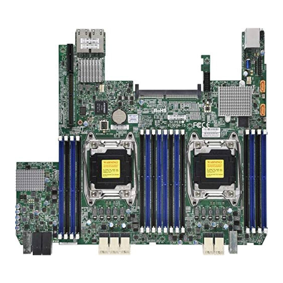
Overview Congratulations on purchasing your computer motherboard from an acknowledged leader in the industry. Supermicro boards are designed with the utmost attention to detail to provide you with the highest standards in quality and performance. This motherboard was designed to be used with a Supermicro-proprietary chassis as an integrated server platform. - Page 10 Super X10DSN-TS Motherboard User’s Manual Motherboard Image Note: All graphics shown in this manual were based upon the latest PCB revision available at the time of publication of the manual. The mother- board you received may or may not look exactly the same as the graphics...
- Page 11 JBT1 FAN2 CPU2_PORT2D X10DSN-TS Battery CPU2_PORT2C Rev. 1.00 CPU2_PORT2B BIOS CPU2_PORT2A MAC CODE LICENSE JSLOT1 SAN MAC IPMI CODE BAR CODE CPU2 CPU1 PM1 PM2 Note: For the latest CPU/Memory updates, please refer to our website at http://www.supermicro.com/products/motherboard/ for details.
-
Page 12: X10Dsn-Ts Quick Reference
Super X10DSN-TS Motherboard User’s Manual X10DSN-TS Quick Reference USB0/1(3.0) SXB1 (Reserved) LAN1 LAN2 LAN CTRL JTPM1 CPU2_PORT1B CPU2_PORT1A JSIOM JBT1 FAN2 CPU2_PORT2D X10DSN-TS Battery CPU2_PORT2C Rev. 1.00 CPU2_PORT2B BIOS CPU2_PORT2A MAC CODE LICENSE JSLOT1 SAN MAC IPMI CODE BAR CODE... - Page 13 (BP) USB 0/1 (3.0) Backpanel USB 3.0 ports 0/1 USB 2 (3.0) Type A USB 3.0 connection header for front access (USB 2) VGA (JVGA1) VGA connection header X10DSN-TS Onboard LED Indicators Description State Status LEDH (Top LED) BMC Heartbeat LED...
- Page 14 Super X10DSN-TS Motherboard User’s Manual Notes...
-
Page 15: Motherboard Features
Chapter 1: Overview Motherboard Features Dual Intel E5-2600v3/v4 series processors (Socket ® R3-LGA 2011) w/dual full-width Intel QuickPath Inter- connect (QPI) links (9.6 GT/s max. one direction per QPI) support Notes: 1. E5-2600v4 requires Revision 2.0 BIOS (or higher). 2. E5-2600v3 is fully back- compatible with all BIOS revisions. - Page 16 • Power-on mode for AC power recovery • Intel® Intelligent Power Node Manager 3.0 (avail- able when the Supermicro Power Manager [SPM] is installed and a special power supply is used. See the note on Page 1-14.) • Management Engine (ME)
- Page 17 CPU TDP sizing. Note 2: For IPMI configuration instructions, please refer to the Embedded IPMI Configuration User's Guide available at http://www.supermicro.com/ support/manuals/. Note 3: It is strongly recommended that you change BMC log-in informa- tion upon initial system power-on.
- Page 18 Super X10DSN-TS Motherboard User’s Manual #1-8 #2-8 #1-7 #2-7 #1-6 #2-6 #1-5 #2-5 #1-4 #2-4 #1-3 #2-3 #1-2 CPU1 CPU0 #2-2 #1-1 #2-1 SNB CORE SNB CORE 9.6G DDR4 DDR4 9.6G DMI2 #3 #2 #1A #1B DMI2 PVCCIO PCI-E X16 G3 (1.05/0.95)
-
Page 19: Processor And Chipset Overview
Processor and Chipset Overview Built upon the functionality and capability of the Intel E5-2600 v3/v4 series proces- sors (Socket R3) and the Intel C612 PCH, the X10DSN-TS motherboard provides system performance, power efficiency, and feature sets required for 40-bay stor- age and virtualization platforms. -
Page 20: Special Features
Super X10DSN-TS Motherboard User’s Manual Special Features Recovery from AC Power Loss The Basic I/O System (BIOS) provides a setting that determines how the system will respond when AC power is lost and then restored to the system. You can choose for the system to remain powered off (in which case you must press the power switch to turn it back on) or for it to automatically return to the power-on state. -
Page 21: Acpi Features
Chapter 1: Overview ACPI Features ACPI stands for Advanced Configuration and Power Interface. The ACPI specifi- cation defines a flexible and abstract hardware interface that provides a standard way to integrate power management features throughout a system, including its hardware, operating system, and application software. This enables the system to automatically turn on and off peripherals such as network cards, hard-disk drives, and printers. -
Page 22: Advanced Power Management
Intel Intelligent Power Node Manager (NM) (Available ® when the Supermicro Power Manager [SPM] is installed) The Intel Intelligent Power Node Manager 3.0 (IPNM) provides your system with ® real-time thermal control and power management for maximum energy efficiency. -
Page 23: Chapter 2 Installation
The following statements are industry-standard warnings, provided to warn the user of situations which might result in bodily injury. Should you have any questions or experience difficulty, contact Supermicro's Technical Support Department for as- sistance. Only certified technicians should attempt to install/change components or configure system settings. - Page 24 Super X10DSN-TS Motherboard User’s Manual Attention Danger d'explosion si la pile n'est pas remplacée correctement. Ne la remplacer que par une pile de type semblable ou équivalent, recommandée par le fabricant. Jeter les piles usagées conformément aux instructions du fabricant.
-
Page 25: Product Disposal
Chapter 2: Installation Product Disposal Warning! Ultimate disposal of this product should be handled according to all national laws and regulations. 製品の廃棄 この製品を廃棄処分する場合、 国の関係する全ての法律 ・ 条例に従い処理する必要が あります。 警告 本产品的废弃处理应根据所有国家的法律和规章进行。 警告 本產品的廢棄處理應根據所有國家的法律和規章進行。 Warnung Die Entsorgung dieses Produkts sollte gemäß allen Bestimmungen und Gesetzen des Landes erfolgen. -
Page 26: Static-Sensitive Devices
Super X10DSN-TS Motherboard User’s Manual القىانين واللىائح الىطنية جميع وفقا ل ينبغي التعامل معه هذا المنتج من التخلص النهائي عند 경고! 이 제품은 해당 국가의 관련 법규 및 규정에 따라 폐기되어야 합니다. Waarschuwing De uiteindelijke verwijdering van dit product dient te geschieden in overeenstemming met alle nationale wetten en reglementen. -
Page 27: Motherboard Installation
• Panhead screws (11 pieces) • Standoffs (11 pieces, if needed) Location of Mounting Holes There are eleven (11) mounting holes on this motherboard as indicated by the arrows. X10DSN-TS Rev. 1.00 BIOS MAC CODE LICENSE SAN MAC IPMI CODE... -
Page 28: Installing The Motherboard
Super X10DSN-TS Motherboard User’s Manual Installing the Motherboard Note: Always connect the power cord last, and always remove it before adding, removing, or changing any hardware components. 1. Locate the mounting holes on the motherboard. X10DSN-TS Rev. 1.00 BIOS MAC CODE... -
Page 29: Processor And Heatsink Installation
CPU socket cap is in place and that none of the socket pins are bent; otherwise, contact your retailer immediately. Refer to the Supermicro website for updates on CPU support. Installing the LGA2011 Processor 1. There are two load levers on the LGA2011 socket. To open the socket cover, first press and release the load lever labeled "Open 1st."... - Page 30 Super X10DSN-TS Motherboard User’s Manual 2. Press the second load lever labeled "Close 1st" to release the load plate that covers the CPU socket from its locking position. Press down on load Pull lever away from lever "Close 1st" socket 3.
- Page 31 Chapter 2: Installation 4. Use your thumb and index finger to loosen the lever and open the load plate. 5. Using your thumb and index finger, hold the CPU by its edges. Align the CPU keys, which are semicircle notches, against the socket keys. Socket Keys CPU Keys 6.
- Page 32 Super X10DSN-TS Motherboard User’s Manual 7. With the CPU inside the socket, inspect the four corners of the CPU to make sure that the CPU is properly installed. Gently close Push down and lock the the load plate lever labeled "Close 1st"...
-
Page 33: Installing A Passive Cpu Heatsink
Chapter 2: Installation Installing a Passive CPU Heatsink 1. Do not apply any thermal grease to the heatsink or the CPU die -- the re- quired amount has already been applied. 2. Place the heatsink on top of the CPU so that the four mounting holes are aligned with those on the motherboard and the heatsink bracket underneath. -
Page 34: Removing The Cpu And The Heatsink
Super X10DSN-TS Motherboard User’s Manual Removing the CPU and the Heatsink Warning: We do not recommend that the CPU or the heatsink be removed. However, if you do need to uninstall the CPU or the heatsink, please follow the instructions below to uninstall the heatsink or the CPU without damaging the CPU or the motherboard. -
Page 35: Installing And Removing The Memory Modules
Chapter 2: Installation Installing and Removing the Memory Modules Note: Check Supermicro's website for a list of recommended memory modules. CAUTION Exercise extreme care when installing or removing DIMM modules to avoid damaging the DIMM modules or the motherboard. Installing & Removing DIMMs 1. - Page 36 Super X10DSN-TS Motherboard User’s Manual Memory Support for the X10DSN-TS Motherboard The X10DSN-TS motherboard supports up to 1 TB of Load Reduced (LRDIMM), Registered (RDIMM) or Non-volatile (NV-DIMM) DDR4 (288-pin) ECC 2400/2133/1866/1600/1333 modules in 16 slots. Memory speed support depends on the CPUs installed in the motherboard.
- Page 37 Chapter 2: Installation Populating RDIMM/LRDIMM DDR4 Memory Modules on the Motherboard Populating RDIMM/LRDIMM DDR4 Memory Modules Speed (MT/s); Voltage (V); Slots per Channel (SPC) and DIMMs per Channel (DPC) Ranks DIMM Capacity 2 Slots per Channel Per DIMM (GB) Type 1 DPC 2 DPC and Data...
-
Page 38: Control Panel Connectors And I/O Ports
Super X10DSN-TS Motherboard User’s Manual Control Panel Connectors and I/O Ports The I/O ports are color-coded in conformance with the industry standards. See the picture below for the colors and locations of the various I/O ports. Back Panel Connectors and I/O Ports USB0/1(3.0) -
Page 39: Universal Serial Bus (Usb)
(Cables are not included.) See the table on the right for pin definitions. 1. Back Panel USB0 (USB3.0) 2. Back Panel USB1 (USB3.0) 3. Type A USB 2 (USB3.0) X10DSN-TS Rev. 1.00 BIOS MAC CODE LICENSE SAN MAC... -
Page 40: Lan Port 1/Lan Port 2
Super X10DSN-TS Motherboard User’s Manual LAN Port 1/LAN Port 2 Two 10_Gigabit Ethernet LAN ports (LAN1, LAN2) are located on the I/O backplane on the motherboard. Both ports accept RJ45 type cables. Please refer to the LED Indicator Section for LAN LED information. -
Page 41: Connecting Cables
USB0/1(3.0) SXB1 B. Fan 2 (Reserved) LAN1 LAN2 C. VGA LAN CTRL JTPM1 CPU2_PORT1B CPU2_PORT1A JSIOM JBT1 FAN2 CPU2_PORT2D X10DSN-TS Battery CPU2_PORT2C Rev. 1.00 CPU2_PORT2B BIOS CPU2_PORT2A MAC CODE LICENSE JSLOT1 SAN MAC IPMI CODE BAR CODE CPU2 CPU1 PM1 PM2... -
Page 42: Dom Power Connectors
Super X10DSN-TS Motherboard User’s Manual DOM Power Connectors DOM PWR Pin Definitions Two power connectors for SATA Pin# Definition DOM (Disk_On_Module) devices are located at JSD1/JSD2. Connect Ground appropriate cables here to provide Ground power supply for your Serial Link DOM devices. -
Page 43: Jumper Settings
A. VGA Enable USB0/1(3.0) SXB1 (Reserved) LAN1 LAN2 LAN CTRL JTPM1 CPU2_PORT1B CPU2_PORT1A JSIOM JBT1 FAN2 CPU2_PORT2D X10DSN-TS Battery CPU2_PORT2C Rev. 1.00 CPU2_PORT2B BIOS CPU2_PORT2A MAC CODE LICENSE JSLOT1 SAN MAC IPMI CODE BAR CODE CPU2 CPU1... -
Page 44: Cmos Clear
Super X10DSN-TS Motherboard User’s Manual CMOS Clear JBT1 is used to clear the CMOS. Instead of pins, this "jumper" consists of contact pads to prevent accidental clearing of the CMOS. To clear the CMOS, use a metal object such as a small screwdriver to touch both pads at the same time to short the connection. -
Page 45: Manufacturer Mode Select
A. Manufacture Mode Select USB0/1(3.0) SXB1 B. BMC Enable (Reserved) LAN1 LAN2 LAN CTRL JTPM1 CPU2_PORT1B CPU2_PORT1A JSIOM JBT1 FAN2 CPU2_PORT2D X10DSN-TS Battery CPU2_PORT2C Rev. 1.00 CPU2_PORT2B BIOS CPU2_PORT2A MAC CODE LICENSE JSLOT1 SAN MAC IPMI CODE BAR CODE CPU2 CPU1... -
Page 46: Onboard Led Indicators
Super X10DSN-TS Motherboard User’s Manual Onboard LED Indicators Link LED Activity LED LAN LEDs There are two LAN ports on the I/O backpanel. These L AN por ts suppor t LAN Activity Indicator (Right) LED Settings 10-Gigabit LAN connections. Each LAN... -
Page 47: Bmc Heartbeat Led
A. BMC Heatbeat LED USB0/1(3.0) B. System Heatbeat LED SXB1 (Reserved) LAN1 LAN2 LAN CTRL JTPM1 CPU2_PORT1B CPU2_PORT1A JSIOM JBT1 FAN2 CPU2_PORT2D X10DSN-TS Battery CPU2_PORT2C Rev. 1.00 CPU2_PORT2B BIOS CPU2_PORT2A MAC CODE LICENSE JSLOT1 SAN MAC IPMI CODE BAR CODE CPU2 CPU1... -
Page 48: 2-10 Sata Connections
S-SATA 3.0 Ports Two S-SATA 3.0 ports (S-SATA0/S-SATA1), supported by the Intel PCH chip, are located on the motherboard. These SATA ports are used with Supermicro SuperDOM (Disk-on-Module) connectors, which are yellow SATA connectors with power-pins built-in, and are backward-compatible with regular SATA HDDs and SATA DOMs. -
Page 49: Chapter 3 Troubleshooting
Chapter 3: Troubleshooting Chapter 3 Troubleshooting Troubleshooting Procedures Use the following procedures to troubleshoot your system. If you have followed all of the procedures below and still need assistance, refer to the "Technical Support Procedures" and/or "Returning Merchandise for Service" section(s) in this chapter. Note: Always disconnect the power cord before adding, changing, or installing any hardware components. -
Page 50: No Video (Available Only When An Internal Speaker Is Installed Onboard)
Super X10DSN-TS Motherboard User’s Manual No Video (Available only when an internal speaker is installed Onboard) 1. If the power is on but you have no video, remove all add-on cards and cables. 2. Use the speaker to determine if any beep codes are present. Refer to Appen- dix A for details on beep codes. -
Page 51: Memory Errors
2. Memory support: Make sure that the memory modules are supported by test- ing the modules using memtest86 or a similar utility. Note: Refer to the product page on our website @ http:\\www.supermicro. com for memory and CPU support and updates. - Page 52 Super X10DSN-TS Motherboard User’s Manual 3. HDD support: Make sure that all hard disk drives (HDDs) work properly. Re- place the bad HDDs with good ones. 4. System cooling: Check the system cooling to make sure that all heatsink fans and CPU/system fans, etc., work properly.
-
Page 53: Technical Support Procedures
Technical Support Procedures Before contacting Technical Support, please take the following steps. Also, please note that as a motherboard manufacturer, Supermicro also sells motherboards through its channels, so it is best to first check with your distributor or reseller for troubleshooting services. -
Page 54: Battery Installation
Super X10DSN-TS Motherboard User’s Manual Battery Removal and Installation Battery Removal To remove the onboard battery, follow the steps below: 1. Power off your system and unplug your power cable. 2. Locate the onboard battery as shown below. 3. Using a tool such as a pen or a small screwdriver, push the battery lock out- wards to unlock it. -
Page 55: Frequently Asked Questions
Note: The SPI BIOS chip used on this motherboard cannot be removed. Send your motherboard back to our RMA Department at Supermicro for repair. For BIOS Recovery instructions, please refer to the AMI BIOS Recovery Instructions posted at http://www.supermicro.com. - Page 56 Super X10DSN-TS Motherboard User’s Manual 3. Insert the USB stick into a USB port, boot to the Build-In UEFI Shell, and type the following commands to start the BIOS update: Shell> fs0: fs0:\> cd UEFI fs0:\UEFI> flash.nsh X11DPDx-xx.xxx 4. The FLASH.NSH script will compare the Flash Descriptor Table (FDT) code in the new BIOS with the existing one in the motherboard: a.
-
Page 57: Returning Merchandise For Service
Shipping and handling charges will be applied for all orders that must be mailed when service is complete. For faster service, You can also request a RMA authorization online (http://www.supermicro.com/RmaForm/). This warranty only covers normal consumer use and does not cover damages in- curred in shipping or from failure due to the alternation, misuse, abuse or improper maintenance of products. -
Page 58: Chapter 4 Bios
When an option is selected in the left frame, it is highlighted in white. Often a text message will accompany it. Note: the AMI BIOS has default text messages built in. Supermicro retains the option to include, omit, or change any of these text messages. -
Page 59: How To Start The Setup Utility
Flashing the wrong BIOS can cause irreparable damage to the system. In no event shall Supermicro be liable for direct, indirect, special, incidental, or consequential damages arising from a BIOS update. If you have to update the BIOS, do not shut down or reset the system while the BIOS is updating to avoid possible boot failure. - Page 60 Chapter 4: AMI BIOS The following Main menu items will be displayed: System Date/System Time Use this option to change the system date and time. Highlight System Date or System Time using the arrow keys. Enter new values using the keyboard. Press the <Tab>...
-
Page 61: Advanced Setup Configurations
Super X10DSN-TS Motherboard User’s Manual Advanced Setup Configurations Use the arrow keys to select Advanced setup and press <Enter> to access the submenu items: Warning: Take Caution when changing the Advanced settings. An incorrect value, a very high DRAM frequency or an incorrect BIOS timing setting may cause the system to malfunction. - Page 62 Chapter 4: AMI BIOS Wait For 'F1' If Error Select Enabled to force the system to wait until the <F1> key is pressed when an error occurs. The options are Disabled and Enabled. INT19 Trap Response Interrupt 19 is the software interrupt that handles the boot disk function. When this item is set to Immediate, the ROM BIOS of the host adaptors will "capture"...
- Page 63 Super X10DSN-TS Motherboard User’s Manual Restore on AC Power Loss Use this feature to set the power state after a power outage. Select Power Off for the system power to remain off after a power loss. Select Power On for the system power to be turned on after a power loss.
- Page 64 Chapter 4: AMI BIOS Cores Enabled This feature allows the user to determine the number of CPU cores to be enabled. Enter "0" to enable all cores. The default setting is 0, which enables all CPU cores in the system. Monitor/Mwait Select Enabled to enable the Monitor/MWait instructions which monitor a region of memory for writes, and will instruct the CPU to stop operation until the monitored...
- Page 65 Super X10DSN-TS Motherboard User’s Manual DCU IP Prefetcher If set to Enable, the IP prefetcher in the DCU (Data Cache Unit) will prefetch IP addresses to improve network connectivity and system performance. The options are Enable and Disable. Direct Cache Access (DCA) Select Enable to use Intel DCA (Direct Cache Access) Technology to improve the efficiency of data transferring and accessing.
- Page 66 Chapter 4: AMI BIOS Energy Performance Bias Setting (Available when Power Technology is set to Custom or Energy Efficient) Use this feature to select an appropriate power setting and performance level for the system. Select Performance to maximize system performance by using maximum amount of power.
- Page 67 Super X10DSN-TS Motherboard User’s Manual CPU HWPM (Hardware Power Management) State Control (Available when Power Technology is set to Custom) Enable CPU HWPM (Hardware Power Management) Select HWPM Native Mode to use hardware power management native mode for CPU power management. Select HWPM OOB Mode to use hardware power management out-of-band mode for CPU power management.
- Page 68 Chapter 4: AMI BIOS Chipset Configuration Warning! Please set the correct settings for the items below. A wrong configuration setting may cause the system to malfunction. North Bridge This feature allows the user to configure the settings for the Intel North Bridge. IIO Configuration EV DFX (Device Function On-Hide) Features When this feature is set to Enable, the EV_DFX Lock Bits that are located on a...
- Page 69 Super X10DSN-TS Motherboard User’s Manual IOU1 (IIO1 PCIe Port 3) This item configures the PCI-E port Bifuraction setting for a PCI-E port specified by the user. The options are x4x4x4x4, x4x4x8, x8x4x4, x8x8, x16, and Auto. IIO1 Port 3A Link Speed This item configures the link speed of a PCI-E port specified by the user.
- Page 70 Chapter 4: AMI BIOS IIO2 Port 3A Link Speed This item configures the link speed of a PCI-E port specified by the user. The options are Gen 1 (Generation 1) (2.5 GT/s), Gen 2 (Generation 2) (5 GT/s), and Gen 3 (Generation 3) (8 GT/s). IOAT Configuration Enable IOAT Select Enable to enable Intel I/OAT (I/O Acceleration Technology), which signifi-...
- Page 71 Super X10DSN-TS Motherboard User’s Manual QPI (Quick Path Interconnect) Configuration QPI General Configuration QPI Status The following information will display: • Number of CPU • Number of II0 • Current QPI Link Speed • Current QPI Link Frequency •...
- Page 72 Chapter 4: AMI BIOS Home Dir Snoop with IVT-Style OSB (Available when the OS and the CPU support this feature) Select Enable for Home-Direct Snoop with IVT-Style_OSB support to enhance system performance. The options are Enable, Disable, and Auto. Isoc Mode Select Enable for Isochronous support to meet QoS (Quality of Service) require- ments.
- Page 73 Super X10DSN-TS Motherboard User’s Manual A7 Mode Select Enable to support A7 (Addressing) mode to improve memory performance. The options are Enable and Disable. DIMM Information This item displays the status of a DIMM module as detected by the AMI BIOS.
- Page 74 Chapter 4: AMI BIOS demand-read command, and the read data from memory turns out to be a correctable error, the error is corrected and sent to the requestor (the original source). Memory is updated as well. Select Enable to use Demand Scrubbing for ECC memory correction.
- Page 75 Super X10DSN-TS Motherboard User’s Manual USB 3.0 Support Select Enabled for USB 3.0 support. The options are Smart Auto, Auto, Enabled, and Disabled. EHCI1 Select Enabled to enable EHCI (Enhanced Host Controller Interface) support on USB 2.0 connector #1 (-at least one USB 2.0 connector should be enabled for EHCI support.) The options are Disabled and Enabled.
- Page 76 Chapter 4: AMI BIOS sSATA Configuration When this submenu is selected, AMI BIOS automatically detects the presence of the s-SATA devices that are supported by the PCH-sSATA controller and displays the following items: sSATA Controller This item enables or disables the onboard SATA controller supported by the Intel PCH chip.
- Page 77 Super X10DSN-TS Motherboard User’s Manual Port 0 ~ Port 3 sSATA Device Type Use this item to specify if the sSATA port specified by the user should be con- nected to a Solid State drive or a Hard Disk Drive. The options are Hard Disk Drive and Solid State Drive.
- Page 78 Chapter 4: AMI BIOS sSATA Port 0 ~ Port 3 Spin Up Device On an edge detect from 0 to 1, set this item to allow the PCH to start a COMRE- SET initialization to the device. The options are Enabled and Disabled. Port 0 ~ Port 3 sSATA Device Type Use this item to specify if the sSATA port specified by the user should be con- nected to a Solid State drive or a Hard Disk Drive.
- Page 79 Super X10DSN-TS Motherboard User’s Manual Above 4G Decoding (Available if the system supports 64-bit PCI decoding) Select Enabled to decode a PCI device that supports 64-bit in the space above 4G Address. The options are Enabled and Disabled. SR-IOV (Available if the system supports Single-Root Virtualization) Select Enabled for Single-Root IO Virtualization support.
- Page 80 Chapter 4: AMI BIOS PCI/PCIX/PCI-E Slot1 OPROM/PCI/PCIX/PCI-E Slot2 OPROM/PCI/PCIX/PCI-E Slot3 OPROM Select Enabled to enable Option ROM support to boot the computer using a de- vice installed on the slot specified by the user. The options are Disabled, Legacy, and EFI. Onboard LAN Option ROM Type Select Enabled to enable Option ROM support to boot the computer using a device installed on the slot specified by the user.
- Page 81 Super X10DSN-TS Motherboard User’s Manual Super IO Configuration Super IO Chip AST2400 Serial Port 1 Configuration Serial Port 1 Select Enabled to enable the onboard serial port specified by the user. The options are Enabled and Disabled. Device Settings This item displays the base I/O port address and the Interrupt Request address for a serial port specified by the user.
- Page 82 Chapter 4: AMI BIOS Console Redirection Settings COM 1 Terminal Type Use this item to select the target terminal emulation type for Console Redirec- tion. Select VT100 to use the ASCII Character set. Select VT100+ to add color and function key support. Select ANSI to use the Extended ASCII Character set. Select VT-UTF8 to use UTF8 encoding to map Unicode characters into one or more bytes.
- Page 83 Super X10DSN-TS Motherboard User’s Manual Recorder Mode Select Enabled to capture the data displayed on a terminal and send it as text messages to a remote server. The options are Disabled and Enabled. Resolution 100x31 Select Enabled for extended-terminal resolution support. The options are Dis- abled and Enabled.
- Page 84 Chapter 4: AMI BIOS Bits Per second Use this feature to set the transmission speed for a serial port used in Console Redirection. Make sure that the same speed is used in the host computer and the client computer. A lower transmission speed may be required for long and busy lines.
- Page 85 Super X10DSN-TS Motherboard User’s Manual Legacy OS Redirection Resolution Use this feature to select the number of rows and columns used in Console Redirection for legacy OS support. The options are 80x24 and 80x25. Putty KeyPad This feature selects Function Keys and KeyPad settings for Putty, which is a terminal emulator designed for the Windows OS.
- Page 86 Chapter 4: AMI BIOS Select VT-UTF8 to use UTF8 encoding to map Unicode characters into one or more bytes. The options are ANSI, VT100, VT100+, and VT-UTF8. Bits Per Second This item sets the transmission speed for a serial port used in Console Redirec- tion.
- Page 87 EV DFX (Device Function On-Hide) support for the system to work properly. (EV DFX is under "IIO Configuration" in the "Chipset/North Bridge" submenu on Page 4-10). For more information on TPM, please refer to the TPM manual at http://www.supermicro.com/manuals/other/ AOM-TPM-9655V_9655H.pdf 4-30...
- Page 88 Chapter 4: AMI BIOS ACPI Settings WHEA Support Select Enabled to support the Windows Hardware Error Architecture (WHEA) plat- form and provide a common infrastructure for the system to handle hardware errors within the Windows OS environment to reduce system crashes and to enhance system recovery and health monitoring.
- Page 89 Super X10DSN-TS Motherboard User’s Manual attached to the adaptors to function as bootable devices at bootup. The options are Immediate and Postponed. Boot Option Filter Use this feature to set the priority for Legacy/UEFI ROMs. The options are UEFI and Lagacy, Legacy only, and UEFI Only.
-
Page 90: Event Logs
Chapter 4: AMI BIOS Event Logs This submenu allows the user to configure Event Log settings. Change SMBIOS Event Log Settings This feature allows the user to configure SMBIOS Event settings. Enabling/Disabling Options SMBIOS Event Log Select Enabled to enable SMBIOS (System Management BIOS) Event Logging during system boot. - Page 91 Super X10DSN-TS Motherboard User’s Manual SMBIOS Event Log Standard Settings Log System Boot Event Select Enabled to log system boot events. The options are Disabled and Enabled. MECI (Multiple Event Count Increment) Enter the increment value for the multiple event counter. Enter a number between 1 to 255.
-
Page 92: Ipmi
Chapter 4: AMI BIOS IPMI This submenu allows the user to configure IPMI settings. The following items will be displayed: • BMC (Baseboard Management Controller) Firmware Revision • IPMI Status System Event Log Enabling/Disabling Options SEL Components Select Enabled to enable all system event logging support at bootup. The options are Enabled and Disabled. - Page 93 Super X10DSN-TS Motherboard User’s Manual When SEL is Full This feature allows the user to determine what the AMI BIOS should do when the system event log is full. Select Erase Immediately to erase all events in the log when the system event log is full.
- Page 94 Chapter 4: AMI BIOS VLAN Select Enabled to enable onboard LAN connections to be used for Intel Virtualization Technology. The options are Enable and Disable. 4-37...
-
Page 95: Security Settings
Super X10DSN-TS Motherboard User’s Manual Security Settings This submenu allows the user to configure the following security settings for the system. Password Check Select Setup for the system to prompt for a password upon entering the BIOS setup utility. Select Always for the system to prompt for a password at bootup and upon entering the BIOS Setup utility. - Page 96 Chapter 4: AMI BIOS • Vendor Keys Secure Boot Select Enable for secure boot support to ensure system security at bootup. The options are Enabled and Disabled. Secure Boot Mode This item allows the user to select the desired secure boot mode for the system. The options are Standard and Custom.
-
Page 97: Boot Settings
Super X10DSN-TS Motherboard User’s Manual Forbidden Signatures This feature allows the user to set and save the forbidden signatures and deny the access to those whose names appear on the list. Authorized TimeStamps This feature allows the user to set and save the timestamps for authorized signa- tures to indicate when these signatures were entered into the system. - Page 98 Chapter 4: AMI BIOS When the item above -"Boot Mode Select" is set to Dual (default), the following items will be displayed for configuration: • Boot Option #1 - Boot Option #15 When the item above -"Boot Mode Select" is set to Legacy, the following items will be display for configuration: •...
-
Page 99: Save & Exit
Super X10DSN-TS Motherboard User’s Manual USB Key Drive BBS Priorities • Legacy Boot Order #1 UEFI USB Key Drive BBS Priorities • UEFI Boot Order #1 Save & Exit This submenu allows the user to configure the following Save & Exit settings:... - Page 100 Chapter 4: AMI BIOS Discard Changes and Exit Select this item to exit from the BIOS setup without making any permanent changes to the system configuration, and reboot the computer. Save Changes and Reset When you have completed the system configuration changes, select this item to leave the BIOS setup utility and reboot the computer for the new system configura- tion parameters to take effect.
-
Page 101: Appendix A Software Installation Instructions
Appendix A Software Installation Instructions A-1 Installing Software Programs The Supermicro FTP site contains drivers and utilities for your system at ftp://ftp. supermicro.com. Some of these must be installed, such as the chipset driver. After accessing the FTP site, go into the CDR_Images directory and locate the ISO file for your motherboard. -
Page 102: A-2 Installing Superdoctor5
Super X10DSN-TS Motherboard User’s Manual A-2 Installing SuperDoctor5 The Supermicro SuperDoctor® 5 is a hardware monitoring program that functions in a command-line or web-based interface in Windows and Linux operating systems. The program monitors system health information, such as CPU temperature, system voltages, system power consumption, and fan speed, and provides alerts via email or the Simple Network Management Protocol (SNMP). -
Page 103: Logging Into The Bmc (Baseboard Management Controller
When logging in to the BMC for the first time, please use the unique password provided by Supermicro to log in. You can change the unique password to a user name and password of your choice for subsequent logins. -
Page 104: Appendix B Uefi Bios Recovery Instructions
Flashing the wrong BIOS can cause irreparable damage to the system. In no event shall Supermicro be liable for direct, indirect, special, incidental, or consequential damages arising from a BIOS update. If you need to update the BIOS, do not shut down or reset the system while the BIOS is updating to avoid possible boot failure. - Page 105 Root "\" Directory of a USB device or a writeable CD/DVD. Note: If you cannot locate the "Super.ROM" file in your driver disk, visit our website at www.supermicro.com to download the BIOS image into a USB flash device and rename it "Super.ROM" for BIOS recovery use.
- Page 106 Appendix B: UEFI BIOS Recovery 4. After locating the new BIOS binary image, the system will enter the BIOS Recovery menu as shown below. Note: At this point, you may decide if you want to start with BIOS recovery. If you decide to proceed with BIOS recovery, follow the procedures below. 5.
- Page 107 Super X10DSN-TS Motherboard User’s Manual 6. After the process of BIOS recovery is completed, press any key to reboot the system. 7. Using a different system, extract the BIOS package into a bootable USB flash drive. 8. When a DOS prompt appears, enter FLASH.BAT BIOSname.### at the prompt.
- Page 108 (Disclaimer Continued) The products sold by Supermicro are not intended for and will not be used in life support systems, medical equipment, nuclear facilities or systems, aircraft, aircraft devices, aircraft/emergency com- munication devices or other critical systems whose failure to perform be reasonably expected to result in significant injury or loss of life or catastrophic property damage.
Need help?
Do you have a question about the X10DSN-TS and is the answer not in the manual?
Questions and answers