Table of Contents
Advertisement
Quick Links
Advertisement
Table of Contents

Related Manuals for Supermicro X10DRX


Summary of Contents for Supermicro X10DRX
- Page 1 X10DRX USER’S MANUAL Revision 1.0...
- Page 2 This product, including software and docu- mentation, is the property of Supermicro and/or its licensors, and is supplied only under a license. Any use or reproduction of this product is not allowed, except as expressly permitted by the terms of said license.
-
Page 3: About This Motherboard
It provides information for the installation and use of the X10DRX motherboard. About This Motherboard The Super X10DRX motherboard supports dual Intel E5-2600v3 series processors (Socket R3) that offer new Intel Microarchitecture 22nm Process Technology, de- livering the best balanced solution of performance, power efficiency, and features to address the diverse needs of next-generation data centers. -
Page 4: Conventions Used In The Manual
X10DRX Motherboard User’s Manual Conventions Used in the Manual Pay special attention to the following symbols for proper system installation: Warning: Important information given to ensure proper system installation or to avoid damaging the components or causing bodily injuries; Note: Additional information given to differentiate between models or... -
Page 5: Contacting Supermicro
Super Micro Computer, Inc. 980 Rock Ave. San Jose, CA 95131 U.S.A. Tel: +1 (408) 503-8000 Fax: +1 (408) 503-8008 Email: marketing@supermicro.com (General Information) support@supermicro.com (Technical Support) Web Site: www.supermicro.com Europe Address: Super Micro Computer B.V. Het Sterrenbeeld 28, 5215 ML... -
Page 6: Table Of Contents
System Resource Alert ................. 1-12 ACPI Features ....................1-13 Power Supply ....................1-13 Advanced Power Management ..............1-14 Intel Intelligent Power Node Manager (NM) (Available when the Supermicro ® Power Manager "SPM" is Installed) .............. 1-14 Management Engine (ME) ................1-14 Chapter 2 Installation Standardized Warning Statements .............. - Page 7 Table of Contents Removing the Passive Heatsink ..............2-12 Installing and Removing the Memory Modules ..........2-13 Installing & Removing DIMMs ............... 2-13 Removing Memory Modules ................. 2-13 Control Panel Connectors and I/O Ports ............2-16 Back Panel Connectors and I/O Ports ............2-16 Serial Ports ....................
- Page 8 X10DRX Motherboard User’s Manual BMC Enable .................... 2-35 LAN Enable/Disable ................. 2-36 C Bus to PCI-Exp. Slots ................ 2-36 Onboard LED Indicators ................2-37 LAN 1/2 LEDs ..................2-37 IPMI-dedicated LAN LEDs ............... 2-37 Onboard Power LED ................2-38 BMC Heartbeat LED ................2-38 2-10 SATA Connections ..................
- Page 9 Table of Contents Appendix A BIOS POST Error Beep Codes BIOS POST Error Beep Codes ...............A-1 Appendix B Software Installation Instructions Installing Software Programs ................B-1 Installing SuperDoctor5 ...................B-2 Appendix C UEFI BIOS Recovery Instructions An Overview to the UEFI BIOS ..............C-1 How to Recover the UEFI BIOS Image (-the Main BIOS Block)....C-1 To Recover the Main BIOS Block Using a USB-Attached Device....C-1...
-
Page 10: Chapter 1 Overview
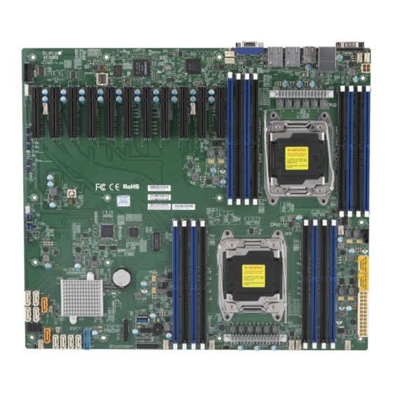
Checklist Congratulations on purchasing your computer motherboard from an acknowledged leader in the industry. Supermicro boards are designed with the utmost attention to detail to provide you with the highest standards in quality and performance. Please check that the following items have all been included with your motherboard. - Page 11 X10DRX Motherboard User’s Manual X10DRX Motherboard Image Note: All graphics shown in this manual were based upon the latest PCB Revision available at the time of publishing of the manual. The motherboard you've received may or may not look exactly the same as the graphics...
- Page 12 Rev. 100 BIOS FAN7 CPU2 CPU1 JBAT1 Battery JBT1 USB 6 (3.0) S-SATA2 S-SATA1 S-SATA0 USB 2/3 (2.0) FAN6 CPU1 FANB Front CTRL Panel JVR1 Note: For the latest CPU/Memory updates, please refer to our website at http://www.supermicro.com/products/motherboard/ for details.
- Page 13 X10DRX Motherboard User’s Manual X10DRX Quick Reference IPMI LAN UID-SW COM1 LAN2 LAN1 USB 0/1 (2.0) USB 4/5 (3.0) JUIDB1 UID-LED LED1 FAN4 FAN5 FANC LAN CTRL BMC CTRL BMC FWR LEM1 CPU2 X10DRX Rev. 100 BIOS FAN7 CPU2 CPU1...
-
Page 14: Jumper Description
Chapter 1: Overview X10DRX Jumpers Jumper Description Default Setting JBT1 Reset BIOS Configuration See Chapter 2 C1/JI SMB to PCI-E Slots Pins 2-3 (Disabled) JPB1 BMC Enable Pins 1-2 (Enabled) JPG1 VGA Enable Pins 1-2 (Enabled) JPL1 LAN 1/2 Enable... - Page 15 X10DRX Motherboard User’s Manual JUIDB1 Unit Identification (UID) switch (BP) USB 0/1 (2.0) Backpanel USB 2.0 ports 0/1 (FP) USB 2/3 (2.0) Front-accessible USB 2.0 connections 2/3 header (BP) USB 4/5 (3.0) Backpanel USB 3.0 ports 4/5 (FP) USB 6 (3.0) Front accessible Type A USB 3.0 port 6...
-
Page 16: Motherboard Features
MHz modules in 16 DIMM slots. Notes: Memory speed support is depending on the CPUs used on the motherboard. For the latest CPU/memory updates, please refer to our website at http://www.supermicro.com/products/ motherboard. Please also refer to the DDR4 Memory Configuration Guide at http://www. supermicro.com/support/resources/memory/ X10_memory_config_guide.pdf. - Page 17 Power-on mode for AC power recovery • Intel Intelligent Power Node Manager 3.0 (Available ® when the Supermicro Power Manager "SPM" is in- stalled and special power supply used. See the note on Page 1-14.) • Management Engine (ME) System...
- Page 18 Note 1: CPU Maximum Thermal Design Power (TDP) is subject to chassis and heatsink cooling restrictions. For proper thermal management, please check the chassis and heatsink specifications for proper CPU TDP sizing. Note 2: For IPMI Configuration Instructions, please refer to the Embedded IPMI Configuration User's Guide available @ http://www.supermicro.com/ support/manuals/.
-
Page 19: System Block Diagram
X10DRX Motherboard User’s Manual X10DRX Block Diagram Rev. 1.00 VCCP0&1 12v VR12.5 PCIE-3.0 x8 * 5 PCIE-2.0 x4 * 1 6 PHASE PCIE2.0 x8 Slots 11(x4) 145W PCIE3.0 x8 Slots [6/7/8/9/10] CPU REAR PROCESSOR 2 CPU FRONT PROCESSOR 1 JLAN1... -
Page 20: Processor And Chipset Overview
Processor and Chipset Overview Built upon the functionality and capability of the Intel E5-2600v3 series proces- sors (Socket R3) and the Intel C612 PCH, the X10DRX motherboard provides the best balanced solution of performance, power efficiency, and features, ideal for enterprise computing and data center environments. -
Page 21: Special Features
X10DRX Motherboard User’s Manual Special Features Recovery from AC Power Loss The Basic I/O System (BIOS) provides a setting that determines how the system will respond when AC power is lost and then restored to the system. You can choose for the system to remain powered off (in which case you must press the power switch to turn it back on), or for it to automatically return to the power-on state. -
Page 22: Acpi Features
As with all computer products, a stable power source is necessary for proper and reliable operation. It is even more important for processors that have high CPU clock rates. The X10DRX motherboard accommodates the following power configurations: • One (1) 24-pin main power connector header (JPWR1), •... -
Page 23: Advanced Power Management
Intel Intelligent Power Node Manager (NM) (Available ® when the Supermicro Power Manager "SPM" is Installed) The Intel Intelligent Power Node Manager 3.0 (IPNM) provides your system with ® real-time thermal control and power management for maximum energy efficiency. -
Page 24: Chapter 2 Installation
The following statements are industry-standard warnings, provided to warn the user of situations which have the potential for bodily injury. Should you have questions or experience difficulty, contact Supermicro's Technical Support department for assis- tance. Only certified technicians should attempt to install or configure components. - Page 25 X10DRX Motherboard User’s Manual Attention Danger d'explosion si la pile n'est pas remplacée correctement. Ne la remplacer que par une pile de type semblable ou équivalent, recommandée par le fabricant. Jeter les piles usagées conformément aux instructions du fabricant. ¡Advertencia! Existe peligro de explosión si la batería se reemplaza de manera incorrecta.
-
Page 26: Product Disposal
Chapter 2: Installation Product Disposal Warning! Ultimate disposal of this product should be handled according to all national laws and regulations. 製品の廃棄 この製品を廃棄処分する場合、 国の関係する全ての法律 ・ 条例に従い処理する必要が あります。 警告 本产品的废弃处理应根据所有国家的法律和规章进行。 警告 本產品的廢棄處理應根據所有國家的法律和規章進行。 Warnung Die Entsorgung dieses Produkts sollte gemäß allen Bestimmungen und Gesetzen des Landes erfolgen. -
Page 27: Static-Sensitive Devices
X10DRX Motherboard User’s Manual 경고! 이 제품은 해당 국가의 관련 법규 및 규정에 따라 폐기되어야 합니다. Waarschuwing De uiteindelijke verwijdering van dit product dient te geschieden in overeenstemming met alle nationale wetten en reglementen. Static-Sensitive Devices Electrostatic Discharge (ESD) can damage electronic com ponents. To avoid dam- aging your system board, it is important to handle it very carefully. -
Page 28: Motherboard Installation
LAN1 USB 0/1 (2.0) USB 4/5 (3.0) JUIDB1 UID-LED LED1 FAN4 FAN5 FANC LAN CTRL BMC CTRL BMC FWR LEM1 CPU2 X10DRX Rev. 100 BIOS FAN7 CPU2 CPU1 JBAT1 Battery JBT1 USB 6 (3.0) S-SATA2 S-SATA1 S-SATA0 USB 2/3 (2.0) -
Page 29: Installing The Motherboard
X10DRX Motherboard User’s Manual Installing the Motherboard Note: Always connect the power cord last, and always remove it before adding, removing or changing any hardware components 1. Locate the matching mounting holes on the chassis. Align the mounting holes on the motherboard against the mounting holes on the chassis. -
Page 30: Processor And Heatsink Installation
CPU socket cap is in place and none of the socket pins are bent; otherwise, contact your retailer immediately. • Refer to the Supermicro website for updates on CPU support. Installing the LGA2011 Processor 1. There are two load levers on the LGA2011 socket. To open the socket cover, first press and release the load lever labeled 'Open 1st'. - Page 31 X10DRX Motherboard User’s Manual 2. Press the second load lever labeled 'Close 1st' to release the load plate that covers the CPU socket from its locking position. Pull lever away from Press down on Load the socket Lever 'Close 1st' 3.
- Page 32 Chapter 2: Installation 4. Use your thumb and your index finger to loosen the lever and open the load plate. 5. Using your thumb and index finger, hold the CPU on its edges. Align the CPU keys, which are semi-circle cutouts, against the socket keys. Socket Keys CPU Keys 6.
- Page 33 X10DRX Motherboard User’s Manual 7. With the CPU inside the socket, inspect the four corners of the CPU to make sure that the CPU is properly installed. Gently close Push down and lock the the load plate. lever labelled 'Close 1st'.
-
Page 34: Installing A Passive Cpu Heatsink
Chapter 2: Installation Installing a Passive CPU Heatsink 1. Apply the proper amount of thermal grease to the heatsink. 2. Place the heatsink on top of the CPU so that the two mounting holes on the heatsink are aligned with those on the retention mechanism. 3. -
Page 35: Removing The Passive Heatsink
X10DRX Motherboard User’s Manual Removing the Passive Heatsink Warning: We do not recommend that the CPU or the heatsink be removed. However, if you do need to remove the heatsink, please follow the instructions below to uninstall the heatsink to avoid damaging the CPU or other components. -
Page 36: Installing And Removing The Memory Modules
Chapter 2: Installation Installing and Removing the Memory Modules Note: Check Supermicro's website for recommended memory modules. CAUTION Exercise extreme care when installing or removing DIMM modules to prevent any possible damage. Installing & Removing DIMMs 1. Insert the desired number of DIMMs into the memory slots, starting with P1-DIMMA1. - Page 37 X10DRX Motherboard User’s Manual Memory Support for the X10DRX Motherboard The X10DRX motherboard supports DDR4 288-pin memory of up to 1024 GB of Load Reduced (LRDIMM) or 512 GB Registered (RDIMM) ECC 2133/1866/1600 MHz modules in 16 DIMM slots. Note1: Memory speed support is depending on the CPUs used in the motherboard.
- Page 38 DDR4 Memory POR for Haswell-EP Chapter 2: Installation Speed (MT/s); Voltage (V); Slot Per Channel (SPC) and DIMM Per Channel (DPC) Ranks Per DIMM DIMM and Capacity (GB) 1 Slot Per 3 Slots Per Channel 2 Slots Per Channel Type Data Channel Width...
-
Page 39: Control Panel Connectors And I/O Ports
X10DRX Motherboard User’s Manual Control Panel Connectors and I/O Ports The I/O ports are color coded in conformance with the industry standards. See the picture below for the colors and locations of the various I/O ports. Back Panel Connectors and I/O Ports... -
Page 40: Serial Ports
USB 4/5 (3.0) JUIDB1 UID-LED LED1 FAN5 FAN4 FANC LAN CTRL 2. COM2 BMC CTRL BMC FWR LEM1 3. VGA CPU2 X10DRX Rev. 100 BIOS FAN7 CPU2 CPU1 JBAT1 Battery JBT1 USB 6 (3.0) S-SATA2 S-SATA1 S-SATA0 USB 2/3 (2.0) -
Page 41: Universal Serial Bus (Usb)
X10DRX Motherboard User’s Manual Universal Serial Bus (USB) Two USB 3.0 ports (USB 4/5) and two USB 2.0 ports (USB 0/1), located on the I/O back panel, provide rear chassis USB support. A Type A USB connector (USB 6), and a USB header with two USB connections (USB 7/8) provide total of three USB 3.0 connections for front access. -
Page 42: Ethernet Ports
USB 4/5 (3.0) UID-LED JUIDB1 LED1 FAN4 FAN5 2. LAN2 FANC LAN CTRL BMC CTRL BMC FWR LEM1 3. IPMI_LAN CPU2 X10DRX Rev. 100 BIOS FAN7 CPU2 CPU1 JBAT1 Battery JBT1 USB 6 (3.0) S-SATA2 S-SATA1 S-SATA0 USB 2/3 (2.0) -
Page 43: Unit Identifier Switches & Uid Led Indicators
X10DRX Motherboard User’s Manual Unit Identifier Switches & UID LED UID Button Indicators Pin# Definition A rear unit identifier switch (JUIDB1) is located Ground next to the VGA port on the IO back panel, and Ground a front UID switch is located on pin 13 on the Button In front control panel (JF1). -
Page 44: Front Control Panel
These connectors are designed specifically for use with Supermicro's server chassis. See the figure below for the descriptions of the various control panel buttons and LED indicators. Refer to the following section for descriptions and pin definitions. -
Page 45: Front Control Panel Pin Definitions
X10DRX Motherboard User’s Manual Front Control Panel Pin Definitions NMI Button NMI Button Pin Definitions (JF1) The non-maskable interrupt button Pin# Definition header is located on pins 19 and 20 Control of JF1. Refer to the table on the right Ground for pin definitions. -
Page 46: Hdd Led/Uid Switch
FAN4 FANC LAN CTRL BMC CTRL BMC FWR LEM1 CPU2 3.3 V FP PWRLED UID Switch HDD LED X10DRX Rev. 100 NIC1 Link LED NIC1 Activity LED BIOS NIC2 Activity LED NIC2 Link LED FAN7 CPU2 CPU1 OH/Fan Fail/ UID LED... -
Page 47: Overheat (Oh)/Fan Fail/Pwr Fail/Uid Led
X10DRX Motherboard User’s Manual Overheat (OH)/Fan Fail/PWR Fail/ OH/Fan Fail/ PWR Fail/Blue_UID UID LED LED Pin Definitions (JF1) Pin# Definition Connect an LED cable to pins 7 and Blue_UID LED 8 of JF1 to use the Overheat/Fan Fail/Power Fail and UID LED connec- OH/Fan Fail/Power Fail tions. -
Page 48: Reset Button
LED1 FAN5 FAN4 Ground FANC LAN CTRL BMC CTRL BMC FWR LEM1 CPU2 FP PWRLED 3.3 V X10DRX HDD LED UID Switch Rev. 100 NIC1 Link LED NIC1 Activity LED BIOS NIC2 Activity LED NIC2 Link LED FAN7 CPU2 CPU1... -
Page 49: Nic1/Nic2 Led Indicators
X10DRX Motherboard User’s Manual NIC1/NIC2 LED Indicators GLAN1/2 LED Pin Definitions (JF1) The NIC (Network Interface Control- Pin# Definition ler) LED connection for LAN port 1 NIC 2 Activity LED is located on pins 11 and 12 of JF1, NIC 2 Link LED... -
Page 50: Connecting Cables
LED1 FAN4 FAN5 FANC LAN CTRL B. 8-pin PWR (JPWR2) BMC CTRL BMC FWR LEM1 C. 8-pin PWR (JPWR3) CPU2 D. 4-pin PWR (JPWR4) X10DRX Rev. 100 BIOS FAN7 CPU2 CPU1 JBAT1 Battery JBT1 USB 6 (3.0) S-SATA2 S-SATA1 S-SATA0 USB 2/3 (2.0) -
Page 51: Fan Headers
X10DRX Motherboard User’s Manual Fan Header Fan Headers Pin Definitions This motherboard has 11 system/cooling Pin# Definition fan headers (FAN1-FAN7, FANA-FAND) Ground on the motherboard. FAN6 is for CPU1, +12V and FAN7, for CPU2. All these 4-pin Tachometer fan headers are backward compatible PWR Modulation with the traditional 3-pin fans. -
Page 52: Internal Speaker
Definition Two external powered SATADOM (Device- on-Module) power connectors are located Ground at JSD1/JSD2 on the motherboard.These Ground connectors provide backward-compatible power support to non-Supermicro SATA- DOMs that require external power supply. IPMI LAN UID-SW COM1 LAN2 LAN1 USB 0/1 (2.0) USB 4/5 (3.0) -
Page 53: Ipmb
X10DRX Motherboard User’s Manual IPMB IPMB Header Pin Definitions A System Management Bus (SMB) Pin# Definition header for IPMI 2.0 is located at JIPMB1. Data Connect the appropriate cable here to Ground use the IPMB I C connection on your Clock system. -
Page 54: Chassis Intrusion
LAN1 USB 4/5 (3.0) JUIDB1 UID-LED LED1 FAN4 FAN5 B. PWR SMB FANC LAN CTRL BMC CTRL BMC FWR LEM1 CPU2 X10DRX Rev. 100 BIOS FAN7 CPU2 CPU1 JBAT1 Battery JBT1 USB 6 (3.0) S-SATA2 S-SATA1 S-SATA0 USB 2/3 (2.0) -
Page 55: Standby Power Header
X10DRX Motherboard User’s Manual Standby Power Header Standby PWR Pin Definitions The +5V Standby Power header is Pin# Definition located at JSTBY1 on the mother- +5V Standby board. See the table on the right for Ground pin definitions. (You must also have a... -
Page 56: Jumper Settings
USB 4/5 (3.0) JUIDB1 UID-LED LED1 A. ME Mode Select FAN5 FAN4 FANC LAN CTRL BMC CTRL BMC FWR LEM1 CPU2 X10DRX Rev. 100 BIOS FAN7 CPU2 CPU1 JBAT1 Battery JBT1 USB 6 (3.0) S-SATA2 S-SATA1 S-SATA0 USB 2/3 (2.0) -
Page 57: Cmos Clear
X10DRX Motherboard User’s Manual CMOS Clear JBT1 is used to clear CMOS. Instead of pins, this "jumper" consists of contact pads to prevent accidental clearing of CMOS. To clear CMOS, use a metal object such as a small screwdriver to touch both pads at the same time to short the connection. -
Page 58: Vga Enable
USB 4/5 (3.0) JUIDB1 UID-LED LED1 VGA Enabled FAN5 FAN4 FANC LAN CTRL BMC CTRL BMC FWR LEM1 BMC Enabled CPU2 X10DRX Rev. 100 BIOS FAN7 CPU2 CPU1 JBAT1 Battery JBT1 USB 6 (3.0) S-SATA2 S-SATA1 S-SATA0 USB 2/3 (2.0) -
Page 59: Lan Enable/Disable
X10DRX Motherboard User’s Manual LAN Enable/Disable LAN Enable JPL1 enables or disables Gigabit LAN Jumper Settings ports 1/2 on the motherboard. See the Jumper Setting Definition table on the right for jumper- settings. The Enabled (default) default setting is Enabled. -
Page 60: Onboard Led Indicators
JUIDB1 UID-LED A. LAN1/2 LEDs LED1 FAN5 FAN4 FANC LAN CTRL BMC CTRL BMC FWR B. IPMI LAN LEDs LEM1 CPU2 X10DRX Rev. 100 BIOS FAN7 CPU2 CPU1 JBAT1 Battery JBT1 USB 6 (3.0) S-SATA2 S-SATA1 S-SATA0 USB 2/3 (2.0) -
Page 61: Onboard Power Led
X10DRX Motherboard User’s Manual Onboard Power LED Onboard PWR LED Indicator LED States An Onboard Power LED is located at LED Color Definition LED2 on the motherboard. When this System Off (PWR cable not connected) LED is on, the system is on. Be sure to... -
Page 62: 2-10 Sata Connections
Intel SCU. I-SATA4/5 can be used with Supermicro SuperDOMs which are yellow SATA DOM connectors with power pins built in, and do not require external power cables. Supermicro SuperDOMs are backward-compatible with regular SATA HDDs or SATA DOMs that need external power cables. -
Page 63: Chapter 3 Troubleshooting
Chapter 3: Troubleshooting Chapter 3 Troubleshooting Troubleshooting Procedures Use the following procedures to troubleshoot your system. If you have followed all of the procedures below and still need assistance, refer to the ‘Technical Support Procedures’ and/or ‘Returning Merchandise for Service’ section(s) in this chapter. Note: Always disconnect the power cord before adding, changing or installing any hardware components. -
Page 64: No Video
X10DRX Motherboard User’s Manual No Video 1. If the power is on, but you have no video, remove all the add-on cards and cables. 2. Use the speaker to determine if any beep codes exist. Refer to Appendix A for details on beep codes. -
Page 65: Memory Errors
2. Memory support: Make sure that the memory modules are supported by test- ing the modules using memtest86 or a similar utility. Note: Refer to the product page on our website http:\\www.supermicro. com for memory and CPU support and updates. - Page 66 X10DRX Motherboard User’s Manual 5. Adequate power supply: Make sure that the power supply provides adequate power to the system. Make sure that all power connectors are connected. Please refer to our website for more information on minimum power require- ment.
-
Page 67: Technical Support Procedures
Technical Support Procedures Before contacting Technical Support, please take the following steps. Also, please note that as a motherboard manufacturer, Supermicro also sells motherboards through its channels, so it is best to first check with your distributor or reseller for troubleshooting services. -
Page 68: Battery Removal And Installation
X10DRX Motherboard User’s Manual Battery Removal and Installation Battery Removal To remove the onboard battery, follow the steps below: 1. Power off your system and unplug your power cable. 2. Locate the onboard battery as shown below. 3. Using a tool such as a pen or a small screwdriver, push the battery lock out- wards to unlock it. -
Page 69: Frequently Asked Questions
Note : The SPI BIOS chip used on this motherboard cannot be removed. Send your motherboard back to our RMA Department at Supermicro for repair. For BIOS Recovery instructions, please refer to the AMI BIOS Recovery Instructions posted at http://www.supermicro.com. -
Page 70: Returning Merchandise For Service
X10DRX Motherboard User’s Manual Returning Merchandise for Service A receipt or copy of your invoice marked with the date of purchase is required before any warranty service will be rendered. You can obtain service by calling your ven- dor for a Returned Merchandise Authorization (RMA) number. When returning the... -
Page 71: Chapter 4 Bios
BIOS Introduction This chapter describes the AMI BIOS setup utility for the X10DRX. It also provides the instructions on how to navigate the AMI BIOS setup utility screens. The AMI ROM BIOS is stored in a Flash EEPROM and can be easily updated. -
Page 72: How To Change The Configuration Data
AMI BIOS setup utility by pressing <F2> at the appropriate time during system boot. Note: For AMI UEFI BIOS Recovery, please refer to the UEFI BIOS Recov- ery User Guide posted at http://www.supermicro.com/support/manuals/. Starting the Setup Utility Normally, the only visible Power-On Self-Test (POST) routine is the memory test. - Page 73 This item displays the system date in Day MM/DD/YY format (e.g. Wed 10/12/2011). System Time This item displays the system time in HH:MM:SS format (e.g. 15:32:52). Supermicro X10DRX BIOS Version This item displays the version of the BIOS ROM used in this system.
-
Page 74: Advanced Setup Configurations
X10DRX Motherboard User’s Manual Advanced Setup Configurations Use the arrow keys to select Advanced Setup and press <Enter> to access the following submenu items. Boot Features Quiet Boot Use this item to select the bootup screen display between POST messages and the OEM logo. -
Page 75: Power Configuration
Chapter 4: AMI BIOS INT19 (Interrupt 19) Trap Response Interrupt 19 is the software interrupt that handles the boot disk function. When this item is set to Immediate, the ROM BIOS of the host adaptors will "capture" Interrupt 19 at bootup immediately and allow the drives that are attached to the host adap- tors to function as bootable disks. -
Page 76: Cpu Configuration
X10DRX Motherboard User’s Manual CPU Configuration This submenu displays the information of a CPU as detected by the BIOS. It also allows the user to configuration CPU settings. Socket 1 CPU Information/Socket 2 CPU Information This submenu displays the following information regarding the CPU installed in Socket 1 and (or) Socket 2 as detected by the BIOS. - Page 77 Chapter 4: AMI BIOS Execute Disable Bit (Available if supported by the OS & the CPU) Select Enable to enable the Execute-Disable Bit which will allow the processor to designate an area in the system memory where an application code can execute and where it cannot, thus preventing a worm or a virus from flooding illegal codes to overwhelm the processor or damage the system during an attack.
-
Page 78: Advanced Power Management Configuration
X10DRX Motherboard User’s Manual Intel® Virtualization Technology (Available when supported by the CPU) Select Enable to support Intel Virtualization Technology, which will allow one platform to run multiple operating systems and applications in independent parti- tions, creating multiple "virtual" systems in one physical computer. The options are Enable and Disable. - Page 79 Chapter 4: AMI BIOS CPU P State Control EIST (P-States) EIST (Enhanced Intel SpeedStep Technology) allows the system to automatically adjust processor voltage and core frequency to reduce power consumption and heat dissipation. The options are Disable and Enable. Turbo Mode (Available when Intel®...
-
Page 80: Chipset Configuration
X10DRX Motherboard User’s Manual CPU T State Control ACPI (Advanced Configuration Power Interface) T-States Select Enable to support CPU throttling by the operating system to reduce power consumption. The options are Enable and Disable. Chipset Configuration North Bridge This feature allows the user to configure the following North Bridge settings. - Page 81 Chapter 4: AMI BIOS CPU1 SLOT2 PCI-E 3.0 x8 Link Speed This item configures the link speed of a PCI-E port specified by the user. The options are Gen 1 (Generation 1) (2.5 GT/s), Gen 2 (Generation 2) (5 GT/s), and Gen 3 (Generation 3) (8 GT/s).
- Page 82 X10DRX Motherboard User’s Manual CPU2 SLOT8 PCI-E 3.0 x8 Link Speed This item configures the link speed of a PCI-E port specified by the user. The options are Gen 1 (Generation 1) (2.5 GT/s), Gen 2 (Generation 2) (5 GT/s), and Gen 3 (Generation 3) (8 GT/s).
- Page 83 Chapter 4: AMI BIOS Intel VT for Directed I/O (VT-d) Intel VT for Directed I/O (VT-d) ® Select Enable to use Intel Virtualization Technology support for Direct I/O VT-d support by reporting the I/O device assignments to the VMM (Virtual Machine Monitor) through the DMAR ACPI Tables.
-
Page 84: Memory Configuration
X10DRX Motherboard User’s Manual COD Enable (Available when the OS and the CPU support this feature) Select Enable for Cluster-On-Die support to enhance system performance in cloud computing. The options are Enable and Disable. Early Snoop (Available when the OS and the CPU support this feature) Select Enable for Early Snoop support to enhance system performance. -
Page 85: Dimm Information
Chapter 4: AMI BIOS Set Throttling Mode Throttling improves reliability and reduces power consumption in the proces- sor via automatic voltage control during processor idle states. The options are Disabled and CLTT (Closed Loop Thermal Throttling). A7 Mode Select Enable to support A7 (Addressing) mode to improve memory performance. The options are Enable and Disable. -
Page 86: South Bridge Configuration
X10DRX Motherboard User’s Manual Demand Scrub Demand Scrubbing is a process that allows the CPU to correct correctable memory errors found on a memory module. When the CPU or I/O issues a demand-read command, and the read data from memory turns out to be a correctable error, the error is corrected and sent to the requestor (the original source). -
Page 87: Sata Configuration
Chapter 4: AMI BIOS USB 3.0 Support Select Enabled for USB 3.0 support. The options are Smart Auto, Auto, Enabled, Disabled and Manual. EHCI1 Select Enabled to enable EHCI (Enhanced Host Controller Interface) support on USB 2.0 connector #1 (-at least one USB 2.0 connector should be enabled for EHCI support.) The options are Disabled and Enabled. - Page 88 X10DRX Motherboard User’s Manual SATA Port 0~ Port 5 This item displays the information detected on the installed SATA drive on the particular SATA port. • Model number of drive and capacity • Software Preserve Support SATA Port 0~ Port 5 Select Enabled to enable a SATA port specified by the user.
- Page 89 Chapter 4: AMI BIOS *If the item above "Configure SATA as" is set to RAID, the following items will display: Support Aggressive Link Power Management When this item is set to Enabled, the SATA AHCI controller manages the power usage of the SATA link. The controller will put the link to a low power state when the I/O is inactive for an extended period of time, and the power state will return to normal when the I/O becomes active.
-
Page 90: Ssata Configuration
X10DRX Motherboard User’s Manual Port 0 ~ Port 5 SATA Device Type Use this item to specify if the SATA port specified by the user should be con- nected to a Solid State drive or a Hard Disk Drive. The options are Hard Disk Drive and Solid State Drive. - Page 91 Chapter 4: AMI BIOS sSATA Port 0 ~ Port 3 Hot Plug Select Enabled to enable hot-plugging support for a port specified by the user, which will allow the user to replace a SATA disk drive installed on this port without shutting down the system.
- Page 92 X10DRX Motherboard User’s Manual Please note that the option-Both is not supported by the Windows Server 2012/ R2 OS. The options are Both, SATA Controller, and sSATA Controller. sSATA Port 0~ Port 3 This item displays the information detected on the installed sSATA drives on the particular sSATA port.
- Page 93 Chapter 4: AMI BIOS • Current State • Error Code PCIe/PCI/PnP Configuration The following PCI information will be displayed: PCI Bus Driver Version PCI Devices Common Settings: PCI PERR/SERR Support Select Enabled for the system to log an error event when a PERR (PCI/PCI-E Parity Error) or a SERR (System Error) occurs.
- Page 94 X10DRX Motherboard User’s Manual MMIOHBase Use this item to select the base memory size according to memory-address map- ping for the IO hub. The base memory size must be between 4032G to 4078G. The options are 56T, 48T, 24T, 512G, and 256G.
-
Page 95: Super Io Configuration
Chapter 4: AMI BIOS Super IO Configuration Super IO Chip AST2400 Serial Port 1 Configuration/Serial Port 2 Configuration Serial Port 1/Serial Port 2 Select Enabled to enable the onboard serial port specified by the user. The options are Enabled and Disabled. Device Settings This item displays the base I/O port address and the Interrupt Request address of a serial port specified by the user. -
Page 96: Com1 Console Redirection Settings
X10DRX Motherboard User’s Manual COM1 Console Redirection Settings Terminal Type This feature allows the user to select the target terminal emulation type for Con- sole Redirection. Select VT100 to use the ASCII Character set. Select VT100+ to add color and function key support. Select ANSI to use the Extended ASCII Char- acter Set. - Page 97 Chapter 4: AMI BIOS Recorder Mode Select Enabled to capture the data displayed on a terminal and send it as text messages to a remote server. The options are Disabled and Enabled. Resolution 100x31 Select Enabled for extended-terminal resolution support. The options are Dis- abled and Enabled.
- Page 98 X10DRX Motherboard User’s Manual Bits Per second Use this feature to set the transmission speed for a serial port used in Console Redirection. Make sure that the same speed is used in the host computer and the client computer. A lower transmission speed may be required for long and busy lines.
- Page 99 Chapter 4: AMI BIOS Legacy OS Redirection Resolution Use this feature to select the number of rows and columns used in Console Redirection for legacy OS support. The options are 80x24 and 80x25. Putty KeyPad Use this item to configure the settings for the function keys and the key pad for Putty, which is a terminal emulator designed for the Windows OS.
-
Page 100: Acpi Settings
X10DRX Motherboard User’s Manual Bits Per Second This item sets the transmission speed for a serial port used in Console Redirec- tion. Make sure that the same speed is used in both host computer and the client computer. A lower transmission speed may be required for long and busy lines. - Page 101 Chapter 4: AMI BIOS Trusted Computing (Available when a TPM device is installed and detected by the BIOS) Configuration Security Device Support If this feature and the TPM jumper on the motherboard are both set to Enabled, onboard security devices will be enabled for TPM support to enhance data integrity and network security.
-
Page 102: Event Logs
X10DRX Motherboard User’s Manual Event Logs Use this feature to configure Event Log settings. Change SMBIOS Event Log Settings This feature allows the user to configure SMBIOS Event settings. Enabling/Disabling Options SMBIOS Event Log Select Enabled to enable SMBIOS (System Management BIOS) Event Logging during system boot. -
Page 103: View Smbios Event Log
Chapter 4: AMI BIOS SMBIOS Event Log Standard Settings Log System Boot Event Select Enabled to log system boot events. The options are Disabled and Enabled. MECI (Multiple Event Count Increment) Enter the increment value for the multiple event counter. Enter a number between 1 to 255. -
Page 104: Ipmi
X10DRX Motherboard User’s Manual IPMI Use this feature to configure Intelligent Platform Management Interface (IPMI) settings. IPMI Firmware Revision This item indicates the IPMI firmware revision used in your system. IPMI Status This item indicates the status of the IPMI firmware installed in your system. -
Page 105: Bmc Network Configuration
Chapter 4: AMI BIOS When SEL is Full This feature allows the user to determine what the BIOS should do when the sys- tem event log is full. Select Erase Immediately to erase all events in the log when the system event log is full. The options are Do Nothing and Erase Immediately. Note: After making changes on a setting, be sure to reboot the system for the changes to take effect. -
Page 106: Security Settings
X10DRX Motherboard User’s Manual Security Settings This menu allows the user to configure the following security settings for the system. Password Check Select Setup for the system to prompt for a password at upon entering the BIOS setup utility. Select Always for the system to prompt for a password at bootup and upon entering the BIOS setup utility. -
Page 107: Secure Boot Menu
Chapter 4: AMI BIOS Secure Boot Menu Secure Boot Select Enable for secure boot support to ensure system security at bootup. The options are Enabled and Disabled. Secure Boot Mode This feature allows the user to select the desired secure boot mode for the system. The options are Standard and Custom. - Page 108 X10DRX Motherboard User’s Manual Append KEK (Key Exchange Key) Select <Yes> to load the new KEK from the manufacture defaults. Select <No> to load the new KEK from other sources. Authorized Signatures Delete DB (DataBase) Select <Yes> to confirm deletion of a database from the system.
-
Page 109: Boot Settings
Chapter 4: AMI BIOS Boot Settings Use this feature to configure Boot Settings: Boot Configuration Setup Prompt Timeout Use this item to indicate how many seconds the system shall wait for the BIOS setup activation key to respond before the system starts to boot. The default setting is 1. Boot Mode Select Use this item to select the type of device to be used for system boot. - Page 110 X10DRX Motherboard User’s Manual Delete Boot Option Use this item to select a boot device to delete from the boot priority list. Delete Boot Option Select the target boot device to delete. Network Drive BBS Priorities • Legacy Boot Order #1...
-
Page 111: Save & Exit
Chapter 4: AMI BIOS Save & Exit Select the Save & Exit tab from the BIOS setup screen to configure the settings below. Discard Changes and Exit Select this option to quit the BIOS setup without making any permanent changes to the system configuration, and reboot the computer. - Page 112 X10DRX Motherboard User’s Manual Restore Defaults Select Restore Defaults from the Exit menu and press <Enter> to load manufacture default settings for your system to maximize system performance but not stability. Save As User Defaults Select Save as User Defaults from the Exit menu and press <Enter> to save changes to the BIOS setup for future use.
-
Page 113: Appendix A Bios Post Error Beep Codes
Appendix A: BIOS POST Error Codes Appendix A BIOS POST Error Beep Codes During the POST (Power-On Self-Test) routines, which are performed at each system boot, errors may occur. Non-fatal errors are those which, in most cases, allow the system to continue to boot. - Page 114 X10DRU-i+ Motherboard User’s Manual Notes...
-
Page 115: Appendix B Software Installation Instructions
Appendix B Software Installation Instructions B-1 Installing Software Programs The Supermicro ftp site contains drivers and utilities for your system at ftp://ftp. supermicro.com. Some of these must be installed, such as the chipset driver. After accessing the ftp site, go into the CDR_Images directory and locate the ISO file for your motherboard. -
Page 116: B-2 Installing Superdoctor5
X10DRX Motherboard User’s Manual B-2 Installing SuperDoctor5 The Supermicro SuperDoctor® 5 is a hardware monitoring program that functions in a command-line or web-based interface in Windows and Linux operating systems. The program monitors system health information such as CPU temperature, system voltages, system power consumption, fan speed, and provides alerts via email or Simple Network Management Protocol (SNMP). -
Page 117: Appendix C Uefi Bios Recovery Instructions
Flashing the wrong BIOS can cause irreparable damage to the system. In no event shall Supermicro be liable for direct, indirect, special, incidental, or consequential damages arising from a BIOS update. If you need to update the BIOS, do not shut down or reset the system while the BIOS is updating to avoid possible boot failure. - Page 118 Root "\" Directory of a USB device or a writeable CD/DVD. Note: If you cannot locate the "Super.ROM" file in your driver disk, visit our website at www.supermicro.com to download the BIOS image into a USB flash device and rename it "Super.ROM" for BIOS recovery use.
- Page 119 Appendix C: UEFI BIOS Recovery 4. After locating the new BIOS binary image, the system will enter the BIOS Recovery menu as shown below. Note: At this point, you may decide if you want to start with BIOS recovery. If you decide to proceed with BIOS recovery, follow the procedures below. 5.
- Page 120 X10DRX Motherboard User’s Manual 6. After the process of BIOS recovery is completed, press any key to reboot the system. 7. Using a different system, extract the BIOS package into a bootable USB flash drive. 8. When a DOS prompt appears, enter FLASH.BAT BIOSname.### at the prompt.
- Page 121 (Disclaimer Continued) The products sold by Supermicro are not intended for and will not be used in life support systems, medical equipment, nuclear facilities or systems, aircraft, aircraft devices, aircraft/emergency com- munication devices or other critical systems whose failure to perform be reasonably expected to result in significant injury or loss of life or catastrophic property damage.
Need help?
Do you have a question about the X10DRX and is the answer not in the manual?
Questions and answers