Table of Contents
Advertisement
Quick Links
Advertisement
Table of Contents

Related Manuals for Supermicro X10DGQ


Summary of Contents for Supermicro X10DGQ
- Page 1 X10DGQ USER’S MANUAL Revision 1.0b...
- Page 2 This product, including software and docu- mentation, is the property of Supermicro and/or its licensors, and is supplied only under a license. Any use or reproduction of this product is not allowed, except as expressly permitted by the terms of said license.
-
Page 3: About This Motherboard
(Socket R3) that offer Intel® QPI (QuickPath Interface) technology, provid- ing point-to-point connections with a transfer speed of up to 9.6 GT/s. With the PCH C612 built in, the X10DGQ motherboard supports the Intel® Manageability Engine, Intel RSTe (Rapid Storage Technology Enterprise), the Digital Media Interface (DMI/ DMI2), PCI-E Gen. -
Page 4: Conventions Used In The Manual
X10DGQ Motherboard User’s Manual Conventions Used in the Manual Pay special attention to the following symbols to properly install the system and to prevent damage to the system or injury to yourself. Warning: Important information given to ensure proper system installation or to prevent damage to the components. -
Page 5: Contacting Supermicro
Super Micro Computer, Inc. 980 Rock Ave. San Jose, CA 95131 U.S.A. Tel: +1 (408) 503-8000 Fax: +1 (408) 503-8008 Email: marketing@supermicro.com (General Information) support@supermicro.com (Technical Support) Website: www.supermicro.com Europe Address: Super Micro Computer B.V. Het Sterrenbeeld 28, 5215 ML... -
Page 6: Table Of Contents
System Health Monitoring ................1-12 ACPI Features ....................1-13 Power Supply ....................1-13 Advanced Power Management ..............1-14 Intel Intelligent Power Node Manager (NM) (Available when the Supermicro ® Power Manager [SPM] is installed)............... 1-14 Management Engine (ME) ................1-14 Chapter 2 Installation Standardized Warning Statements .............. - Page 7 Table of Contents Connecting Cables ..................2-21 Power Connectors ................... 2-21 Fan Headers ..................... 2-22 TPM Header/Port 80 ................2-23 Standby Power Header ................2-23 T-SGPIO1 Header ..................2-24 Internal Speaker ..................2-24 Chassis Intrusion ..................2-25 Universal Serial Bus (USB) ..............2-25 Jumper Settings ....................
- Page 8 X10DGQ Motherboard User’s Manual Boot Settings ....................4-47 Save & Exit ....................4-49 Appendix A BIOS POST Error Beep Codes BIOS Error Beep Codes .................A-1 Appendix B Software Installation Instructions Installing Software Programs ................B-1 Configuring SuperDoctor 5 ................B-2 Appendix C UEFI BIOS Recovery Instructions An Overview to the UEFI BIOS ..............C-1...
-
Page 9: Chapter 1 Overview
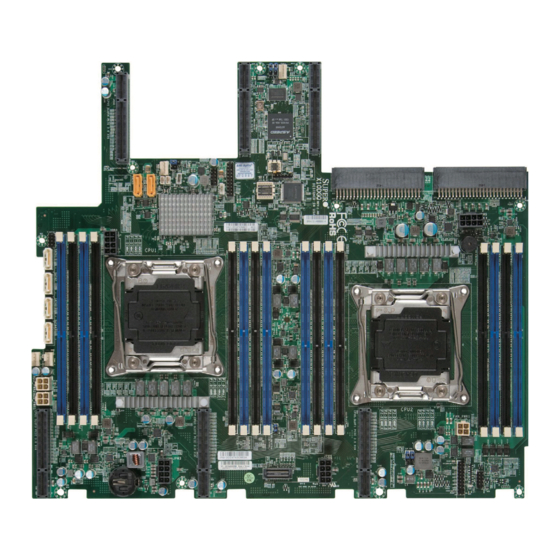
Checklist Congratulations on purchasing your computer motherboard from an acknowledged leader in the industry. Supermicro boards are designed with the utmost attention to detail to provide you with the highest standards in quality and performance. The X10DGQ motherboard was designed to be used with a Supermicro-proprietary chassis as an integrated GPU server platform. - Page 10 X10DGQ Motherboard User’s Manual Motherboard Image Note: All graphics shown in this manual were based upon the latest PCB revision available at the time of publication of the manual. The motherboard you've received may or may not look exactly the same as the graphics...
-
Page 11: Motherboard Layout
Notes: 1. For the latest CPU/memory updates, please refer to our website at http:// www.supermicro.com/products/motherboard/ for details. 2. Use only the correct type of onboard CMOS battery as specified by the manufacturer. Do not install the onboard battery upside down to avoid... - Page 12 X10DGQ Motherboard User’s Manual X10DGQ Motherboard Quick Reference BIOS JSLOT6 JPME2 BIOS LICENSE JBT1 JPW1 JPW2 JPW4 JPW5 X10DGQ Rev. 1.00 CPU2 CPU1 FAN_PWR1 JPW3 IPMI CODE BATTERY BAR CODE JITP1 FAN5 JPW6 Notes: • See Chapter 2 for detailed information jumpers, I/O ports, connectors, and expansion slots.
- Page 13 SMCI proprietary 50-pin power connectors 1/2 JSTBY1 Standby power header SATA1-6 SATA connectors 1-6 supported by Intel PCH (SATA5/6: sup- port Supermicro SuperDOM with power pins built-in) (CPU1) Slot3/4 PCI-E 3.0 x16 slots 3/4 (CPU2) Slot1/2 PCI-E 3.0 x16 slots 1/2 (CPU0/1) Slot5 PCI-E 3.0 x8/x8 slot 5...
- Page 14 X10DGQ Motherboard User’s Manual Notes Warning: Do not install the onboard battery upside down to avoid damaging the components or the motherboard. Also, be sure to follow the instructions given by your local hazardous materials management agency to properly dispose of the used bat-...
-
Page 15: Motherboard Features
GB of Registered (RDIMM) DDR4 (288-pin) ECC 2400/2133/1866/1600 MHz memory in 16 slots Note: Memory speed support depends on the processors installed in the system. For the latest CPU/memory updates, please refer to our website at http://www.supermicro.com/ products/motherboard. DIMM Sizes 128GB @ 1.20V •... -
Page 16: Peripheral Devices
Power ACPI Power Management • Config. Main switch override mechanism • Power-on mode for AC power recovery • Intel Intelligent Power Node Manager (available ® when the Supermicro Power Manager [SPM] is installed) • Management Engine • Riser Card auto-detection... - Page 17 CPU TDP sizing. Note 2: For IPMI configuration instructions, please refer to the Embedded IPMI Configuration User's Guide available @ http://www.supermicro.com/ support/manuals/. Note 3: It is strongly recommended that you change BMC log-in informa- tion upon initial system power-on.
-
Page 18: System Block Diagram
X10DGQ Motherboard User’s Manual #2-8 #2-7 #2-6 145W 145W #1-8 #2-5 #1-7 #2-4 #1-6 #2-3 #1-5 #2-2 #2-1 #1-4 #1-3 #1-2 #1-1 CPU2 DDR4 DDR4 9.6G CPU1 9.6G DMI2 4GB/s AOM-PIO-i2G/i2XT PCI-E X4 G2 #1-4 Rear IO riser card USB3.0 x2 6.0 Gb/S... -
Page 19: Processor And Chipset Overview
Processor and Chipset Overview Built upon the functionality and capability of the Intel E5-2600(v3/v4) series processors (Socket R3) and the Intel C612 PCH, the X10DGQ motherboard is optimized for high-performance computing (HPC) and is ideal for scientific visual- ization platforms. -
Page 20: Special Features
X10DGQ Motherboard User’s Manual Special Features Recovery from AC Power Loss The Basic I/O System (BIOS) provides a setting that determines how the system will respond when AC power is lost and then restored to the system. You can choose for the system to remain powered off (in which case you must press the power switch to turn it back on) or for it to automatically return to the power-on state. -
Page 21: Acpi Features
Chapter 1: Overview ACPI Features ACPI stands for Advanced Configuration and Power Interface. The ACPI specifica- tion defines a flexible and abstract hardware interface that provides a standard way to integrate power management features throughout a computer system, including its hardware, operating system, and application software. This enables the system to automatically turn on and off peripherals such as network cards, hard disk drives, and printers. -
Page 22: Advanced Power Management
The following advanced power management features are supported by the moth- erboard. Intel Intelligent Power Node Manager (NM) (Available ® when the Supermicro Power Manager [SPM] is installed) The Intel Intelligent Power Node Manager (IPNM) provides your system with ® real-time thermal control and power management for maximum energy efficiency. -
Page 23: Chapter 2 Installation
The following statements are industry-standard warnings, provided to warn the user of situations where bodily injury might occur. Should you have questions or experi- ence difficulty, contact Supermicro's Technical Support department for assistance. Only certified technicians should attempt to install or configure components. - Page 24 X10DGQ Motherboard User’s Manual Attention Danger d'explosion si la pile n'est pas remplacée correctement. Ne la remplacer que par une pile de type semblable ou équivalent, recommandée par le fabricant. Jeter les piles usagées conformément aux instructions du fabricant. ¡Advertencia! Existe peligro de explosión si la batería se reemplaza de manera incorrecta.
-
Page 25: Product Disposal
Chapter 2: Installation Product Disposal Warning! Ultimate disposal of this product should be handled according to all national laws and regulations. 製品の廃棄 この製品を廃棄処分する場合、 国の関係する全ての法律 ・ 条例に従い処理する必要が あります。 警告 本产品的废弃处理应根据所有国家的法律和规章进行。 警告 本產品的廢棄處理應根據所有國家的法律和規章進行。 Warnung Die Entsorgung dieses Produkts sollte gemäß allen Bestimmungen und Gesetzen des Landes erfolgen. -
Page 26: Static-Sensitive Devices
X10DGQ Motherboard User’s Manual Static-Sensitive Devices Electrostatic discharge (ESD) can damage electronic com ponents. To avoid possible damage to your system motherboard, it is important to handle it very carefully. The following measures are generally sufficient to protect your equipment from ESD. -
Page 27: Motherboard Installation
Location of Mounting Holes There are twelve (12) mounting holes on this motherboard indicated by the arrows. BIOS JSLOT6 JPME2 BIOS LICENSE JBT1 JPW2 JPW1 JPW4 JPW5 X10DGQ Rev. 1.00 CPU2 CPU1 FAN_PWR1 JPW3 IPMI CODE BATTERY BAR CODE JITP1 FAN5 JPW6... -
Page 28: Installing The Motherboard
X10DGQ Motherboard User’s Manual Installing the Motherboard Note: Always connect the power cord last, and always remove it before adding, removing, or changing any hardware components. Install the I/O shield into the chassis. 1. Locate the mounting holes on the motherboard. -
Page 29: Processor And Heatsink Installation
CPU socket cap is in place and that none of the socket pins are bent; otherwise, contact your retailer immediately. • Refer to the Supermicro website for updates on CPU support. Installing the LGA2011 Processor 1. There are two load levers on the LGA2011 socket. To open the socket cover, first press and release the load lever labeled "Open 1st."... - Page 30 X10DGQ Motherboard User’s Manual 2. Press the second load lever labeled "Close 1st" to release the load plate that covers the CPU socket from its locking position. Press down on the load Pull the lever away lever labeled "Close 1st."...
- Page 31 Chapter 2: Installation 4. Using your thumb and the index finger, remove from the socket the plastic cap with the warning label. 5. Use your thumb and index finger to hold the CPU on its edges. Align the CPU keys, which are semicircle cutouts, against the socket keys. Socket Keys CPU Keys 6.
- Page 32 X10DGQ Motherboard User’s Manual 7. With the CPU inside the socket, inspect the four corners of the CPU to make sure that the CPU is properly installed. 8. Close the load plate with the CPU inside the socket. Lock the lever labeled "Close 1st"...
-
Page 33: Installing A Passive Heatsink
Chapter 2: Installation Installing a Passive Heatsink 1. Apply the proper amount of thermal grease to the heatsink. 2. Place the heatsink on top of the CPU so that the two mounting holes on the heatsink are aligned with those on the retention mechanism. 3. -
Page 34: Removing The Passive Heatsink
X10DGQ Motherboard User’s Manual Removing the Passive Heatsink Warning: We do not recommend that the CPU or the heatsink be removed. However, if you do need to remove the heatsink, please follow the instructions below to uninstall the heatsink to avoid damaging the CPU or other components. -
Page 35: Installing And Removing The Memory Modules
Chapter 2: Installation Installing and Removing the Memory Modules Note: Check Supermicro's website for recommended memory modules. CAUTION Exercise extreme care when installing or removing DIMM modules to prevent any possible damage. Installing & Removing DIMMs 1. Insert the desired number of DIMMs into the memory slots, starting with P1-DIMMA1. - Page 36 X10DGQ Motherboard User’s Manual Memory Support for the X10DGQ Motherboard The X10DGQ motherboard supports up to 2048 GB of Load Reduced (LRDIMM) and up to 512 GB of Registered (RDIMM) DDR4 (288-pin) ECC 2400/2133/1866/1600 MHz memory in 16 slots Note: Memory speed support depends on the processors installed in the system.
- Page 37 Chapter 2: Installation Populating RDIMM/LRDIMM DDR4 Memory Modules for the E5- 2600v3-based Motherboard Speed (MT/s); Voltage (V); Slot Per Channel (SPC) and DIMM Per Channel (DPC) DIMM Capacity Ranks Per (GB) DIMM and Type 1 Slot Per Data 2 Slots Per Channel Channel Width 1DPC...
-
Page 38: Front Control Panel
These connectors are designed spe- cifically for use with Supermicro's chassis. See the figure below for the descriptions of the control panel buttons and LED indicators. Refer to the following section for descriptions and pin definitions. -
Page 39: Front Control Panel Pin Definitions
A. NMI B. PWR LED Ground FP PWRLED 3.3 V UID Switch HDD LED NIC1 Link LED NIC1 Activity LED X10DGQ Rev. 1.00 NIC2 Activity LED NIC2 Link LED OH/Fan Fail/ UID LED PWR Fail LED) Power Fail LED 3.3V... -
Page 40: Hdd Led
X10DGQ Motherboard User’s Manual HDD LED HDD LED Pin Definitions (JF1) The HDD LED connection is located Pin# Definition on pins 13 and 14 of JF1. Attach a UID Switch cable here to indicate HDD activ- HD Active ity. See the table on the right for pin definitions. -
Page 41: Overheat (Oh)/Fan Fail/Pwr Fail
PWR Supply Fail definitions. A. OH/Fail/PWR Fail LED B. PWR Supply Fail Ground 3.3 V FP PWRLED X10DGQ UID Switch HDD LED Rev. 1.00 NIC1 Link LED NIC1 Activity LED NIC2 Activity LED NIC2 Link LED... -
Page 42: Reset Button
X10DGQ Motherboard User’s Manual Reset Button Reset Button Pin Definitions (JF1) The Reset Button connection is located Pin# Definition on pins 3 and 4 of JF1. Attach it to a Reset hardware reset switch on the computer Ground case. Refer to the table on the right for pin definitions. -
Page 43: Connecting Cables
A. JPW1: 50-pin SMCI-proprietary main power (Req'd) B. JPW2: 50-pin SMCI-proprietary main power (Req'd) C. JPW3: 8-pin power (Req'd) X10DGQ Rev. 1.00 D. JPW4: 8-pin power (Req'd) E. JPW5: 8-pin power (Req'd) F. JPW6: 8-pin power (Req'd) G. HDD_PWR1: 4-pin HDD power (Req'd) H. -
Page 44: Fan Headers
X10DGQ Motherboard User’s Manual Fan Headers Fan Header Pin Definitions A four-pin fan (FAN8-FAN11) is located on the Pin# Definition motherboard for system cooling. The 4-pin fans Ground headers are backward compatible with the tradi- +12V tional 3-pin fans. However, fan-speed control is... -
Page 45: Tpm Header/Port 80
See the table on the right for pin defini- Ground tions. (You must also have a card with the No Connection standby power connector and a cable to use this feature.) A. TPM/Port80 B. Standby Power X10DGQ Rev. 1.00 IPMI CODE BAR CODE 2-23... -
Page 46: T-Sgpio1 Header
X10DGQ Motherboard User’s Manual T-SGPIO1 Header T-SGPIO Pin Definitions One SGPIO (Serial-Link General-Purpose Pin# Definition Pin# Definition Input/Output) header (T-SGPIO1) is located on the motherboard. This header supports Ground Data a serial-link interface for onboard SATA con- Load Ground nections. See the table on the right for pin Clock definitions. -
Page 47: Chassis Intrusion
(USB 2/3) for front panel access. USB_PP2 USB_PP3 (Cables are not included.) See the table on the right for pin definitions. Ground Ground No Connection A. Chassis Intrusion B. USB 2/3 X10DGQ Rev. 1.00 IPMI CODE BAR CODE 2-25... -
Page 48: Jumper Settings
X10DGQ Motherboard User’s Manual Jumper Settings Explanation of Jumpers Connector Pins To modify the operation of the motherboard, jumpers can be used to choose between optional settings. Jumpers create shorts be- Jumper tween two pins to change the function of the connector. -
Page 49: Cmos Clear
See the table on the right for jumper settings. Watch Dog must also be enabled in the BIOS. A. Clear CMOS B. Watch Dog Enable X10DGQ Rev. 1.00 IPMI CODE BAR CODE 2-27... -
Page 50: Vga Enable
X10DGQ Motherboard User’s Manual VGA Enable VGA Enable Jumper Settings Jumper JPG1 allows the user to enable Jumper Setting Definition the onboard VGA connector. The default Enabled (Default) setting is on pins 1/2 to enable the con- Disabled nection. See the table on the right for jumper settings. -
Page 51: Onboard Led Indicators
LE6 on the motherboard. See the table Green System power on at right for more information. Amber Standby power only System power failure A. System PWR LED B. Power Health LED X10DGQ Rev. 1.00 IPMI CODE BAR CODE 2-29... -
Page 52: Bmc Heartbeat Led
X10DGQ Motherboard User’s Manual BMC Heartbeat LED BMC Heartbeat LED Status A BMCHear tbeat LED is located at Color/State Definition LEDM1 on the motherboard. When Green: BMC: Normal LEDM1 is blinking, BMC functions nor- Blinking mally. See the table at right for more information. -
Page 53: 2-10 Serial Ata Connections
Parallel ATA. See the table on the right for pin definitions. Note: Please refer to the Intel SATA HostRAID User's Guide posted on our website @ http://www.supermicro.com for more information on the SATA. A. SATA1 B. SATA2 C. SATA3 D. - Page 54 X10DGQ Motherboard User’s Manual Notes 2-32...
-
Page 55: Chapter 3 Troubleshooting
Chapter 3: Troubleshooting Chapter 3 Troubleshooting Troubleshooting Procedures Use the following procedures to troubleshoot your system. If you have followed all of the procedures below and still need assistance, refer to the Technical Support Procedures and/or the Returning Merchandise for Service section in this chapter. Note: Always disconnect the power cord before adding, changing, or installing any hardware components. -
Page 56: System Boot Failure
X10DGQ Motherboard User’s Manual No Video 1. If the power is on but you do not have video, remove all the add-on cards and cables. 2. Use the speaker to determine if any beep codes exist. Refer to Appendix A for details on beep codes. -
Page 57: Memory Errors
2. Memory support: Make sure that the memory modules are supported by test- ing the modules using memtest86 or a similar utility. Note: Refer to the product page on our website http:\\www.supermicro. com for memory and CPU support and updates. - Page 58 X10DGQ Motherboard User’s Manual settings in the IPMI to make sure that the CPU and system temperatures are within the normal range. Also check the front-panel Overheat LED and make sure that the Overheat LED is not on. 5. Adequate power supply: Make sure that the power supply provides adequate power to the system.
-
Page 59: Technical Support Procedures
Technical Support Procedures Before contacting Technical Support, please take the following steps. Also, please note that as a motherboard manufacturer, Supermicro also sells motherboards through its channels, so it is best to first check with your distributor or reseller for troubleshooting services. -
Page 60: Battery Removal And Installation
X10DGQ Motherboard User’s Manual Battery Removal and Installation Battery Removal To remove the onboard battery, follow the steps below: 1. Power off your system and unplug your power cable. 2. Locate the onboard battery as shown below. 3. Using a tool such as a pen or a small screwdriver, push the battery lock out- wards to unlock it. -
Page 61: Frequently Asked Questions
Note: The SPI BIOS chip used on this motherboard cannot be removed. Send your motherboard back to our RMA Department at Supermicro for repair. For BIOS recovery instructions, please refer to the AMI BIOS Re- covery Instructions posted at http://www.supermicro.com. -
Page 62: Returning Merchandise For Service
X10DGQ Motherboard User’s Manual Returning Merchandise for Service A receipt or copy of your invoice marked with the date of purchase is required before any warranty service will be rendered. You can obtain service by calling your ven- dor for a Returned Merchandise Authorization (RMA) number. When returning the... -
Page 63: Chapter 4 Bios
BIOS Introduction This chapter describes the AMI BIOS setup utility for the X10DGQ motherboard. It also provides the instructions on how to navigate the AMI BIOS setup utility screens. The AMI ROM BIOS is stored in a Flash EEPROM and can be easily updated. -
Page 64: How To Change The Configuration Data
<Delete> at the appropriate time during system boot. Note: For AMI UEFI BIOS Recovery, please refer to the UEFI BIOS Recov- ery User Guide posted @ http://www.supermicro.com/support/manuals/. Starting the Setup Utility Normally, the only visible Power-On Self-Test (POST) routine is the memory test. - Page 65 The date must be entered in Day MM/DD/YYYY format. The time is entered in HH:MM:SS format. (Note: The time is in the 24-hour format. For example, 5:30 P.M. appears as 17:30:00.). Supermicro X10DGQ BIOS Version This item displays the SMC version of the BIOS ROM used in this system.
-
Page 66: Advanced Setup Configurations
X10DGQ Motherboard User’s Manual Advanced Setup Configurations Select the Advanced tab to access the following submenu items. Boot Features Boot Configuration Quiet Boot Use this item to select bootup screen display between POST messages and the OEM logo. Select Disabled to display the POST messages. Select Enabled to display the OEM logo instead of the normal POST messages. -
Page 67: Power Configuration
Chapter 4: AMI BIOS Wait For 'F1' If Error Select Enabled to force the system to wait until the 'F1' key is pressed when an error occurs. The options are Disabled and Enabled. Interrupt 19 Capture Interrupt 19 is the software interrupt that handles the boot disk function. When this item is set to Immediate, the BIOS ROM of the host adaptors will immediately capture Interrupt 19 at bootup and allow the drives that are attached to these host adaptors to function as bootable disks. - Page 68 X10DGQ Motherboard User’s Manual Processor 0/Processor 1 This submenu displays the following information of the CPU installed in Socket 0, and Socket 1. • Processor Socket • Processor ID • Processor Frequency • Processor Max Ratio • Processor Min Ratio •...
- Page 69 Chapter 4: AMI BIOS The options are Enable and Disable. (Refer to Intel and Microsoft websites for more information.) PPIN Control Select Unlock/Enable to use the Protected-Processor Inventory Number (PPIN) in the system. The options are Unlock/Enable and Unlock/Disable. Hardware Prefetcher (Available when supported by the CPU) If set to Enable, the hardware prefetcher will prefetch streams of data and instruc- tions from the main memory to the L2 cache to improve CPU performance.
-
Page 70: Advanced Power Management Configuration
X10DGQ Motherboard User’s Manual Intel Virtualization Technology (Available when supported by the CPU) ® Select Enable to support Intel Virtualization Technology, which will allow one platform to run multiple operating systems and applications in independent parti- tions, creating multiple "virtual" systems in one physical computer. The options are Enable and Disable. - Page 71 Chapter 4: AMI BIOS Turbo Mode Select Enable to use the Turbo Mode to boost system performance. The options are Disable and Enable. P-state Coordination This item is used to change the P-state (Power-Performance State) coordination type. P-state is also known as "SpeedStep" for Intel processors. Select HW_ALL to change the P-state coordination type for hardware components only.
-
Page 72: Chipset Configuration
X10DGQ Motherboard User’s Manual Chipset Configuration North Bridge This feature is used to configure Intel North Bridge settings. IIO (Integrated IO) Configuration EV DFX (Device Function On-Hide) Features When this item is set to Enable, the EV_DFX Lock Bits that are located on a processor will always remain clear during electric tuning. - Page 73 Chapter 4: AMI BIOS Link Speed Use this item to select the PCI-E link speed for the PCI-E port specified by the user. The options for CPU-PCH DMI port and are GEN1 (2.5 GT/s), GEN2 (5 GT/s), and Auto. The options for Onboard LAN port, CPU1 Slot1 x8 port, and CPU1 Slot2 x16 port are GEN1 (2.5 GT/s), GEN2 (5 GT/s), GEN3 (8 GT/s), and Auto.
- Page 74 X10DGQ Motherboard User’s Manual Socket 0 PCIeD01F0 - Port 1A/Socket 0 PCIeD02F0 - Port 2A/Socket 0 PCIeD03F2 - Port 3A PCI-E Port Select Enable to enable the PCI-E port specified by the user. The options are Auto, Enable, and Disable.
- Page 75 Chapter 4: AMI BIOS Fatal Err (Error) Over Select Enable to force fatal error prorogation to the IIO core error logic for the port specified by the user. The options are Disable and Enable. Non-Fatal Err (Error) Over Select Enable to force non-fatal error prorogation to the IIO core error logic for the port specified by the user.
- Page 76 X10DGQ Motherboard User’s Manual Gen3 (Generation 3) DN RX Preset Hint Use this item to set the Preset Hint mode for PCI-E Gen3 downstream recep- tion (from a slave device to the master device). The options are Auto, P0 (-6.0 dB), P1 (-7.0 dB), P2 (-8.0 dB), P3 (-9.0 dB), P4 (-10.0 dB), P5 (-11.0 dB), and...
- Page 77 Chapter 4: AMI BIOS No PCIe Port Active ECO Use this feature to select a workaround setting to implement the engineering- change order (ECO) on the system when the PCI ports specified by the user are not active. The options are PCU Squelch exit ignore option and Reset the SQ FLOP by CSR option.
- Page 78 X10DGQ Motherboard User’s Manual PCI-E Port L1 Exit Latency Use this feature to set the length of time required for the port specified by the user to complete the transition from L1 to L0. The default setting is <1uS, 1uS - 2uS, 2uS - 4uS, 4uS - 8uS, 8uS - 16uS, 16uS - 32uS, 32uS - 64uS, and >64uS.
- Page 79 Chapter 4: AMI BIOS dB), P1 (-3.5/0.0 dB), P2 (-4.5/0.0 dB), P3 (-2.5/0.0 dB), P4 (0.0/0.0 dB), P5 (0.0/2.0 dB), P6 (0.0/2.5 dB), P7 (-6.0 /3.5 dB), P8 (-3.5/3.5 dB), and P9 (0.0/3.5 dB). Gen3 (Generation 3) DN RX Preset Hint Use this item to set the Preset Hint mode for PCI-E Gen3 downstream recep- tion (from a slave device to the master device).
- Page 80 X10DGQ Motherboard User’s Manual Relaxed Ordering Select Enable for relaxed ordering support, which will allow certain transactions to be processed and completed prior to other transactions that have already been queued and that violate the strict ordering rules of PCI processing. The options are Disable and Enable.
-
Page 81: Memory Configuration
Chapter 4: AMI BIOS Link L0p Enable Select Enable for Link L0p support. The options are Disable and Enable. Link L1 Enable Select Enable for Link L1 support. The options are Disable and Enable. Early Snoop Select Enable to support Early Snoop mode for the QPI link. The options are Disable, Enable, and Auto. -
Page 82: Dimm Information
X10DGQ Motherboard User’s Manual A7 Mode Select Enabled to support the A7 (Addressing) mode to improve memory per- formance. The options are Disable and Enable. DIMM Information This item displays the status of a DIMM module as detected by the BIOS. -
Page 83: South Bridge Configuration
Chapter 4: AMI BIOS Demand Scrub Demand Scrubbing is a process that allows the CPU to correct correctable memory errors found on a memory module. When the CPU or I/O issues a demand-read command, and the read data from memory turns out to be a correctable error, the error is corrected and sent to the requestor (the original source). -
Page 84: Sata Configuration
X10DGQ Motherboard User’s Manual USB 3.0 Support Select Enabled for USB 3.0 support. The options are Smart Auto, Auto, Enabled, and Disabled. SATA Configuration When this submenu is selected, AMI BIOS automatically detects the presence of the SATA devices and displays the following items:... - Page 85 Chapter 4: AMI BIOS SATA Port 0-Port 5 Spin Up Device On an edge detect from 0 to 1, select Enabled to allow the PCH to initialize the device. The options are Disabled and Enabled. SATA Port 0-Port 5 SATA Device Type Use this item to specify if the SATA port specified by the user should be con- nected to a Solid State drive or a Hard Disk Drive.
-
Page 86: Ssata Configuration
X10DGQ Motherboard User’s Manual Serial ATA Port 0-Port 5 This item displays the information detected on the installed SATA drives on the particular SATA port. • Model number of drive and capacity • Software Preserve Support Serial ATA Port 0-Port 5 Select Enabled to enable a SATA port specified by the user. - Page 87 Chapter 4: AMI BIOS *If the item above "Configure sSATA as" is set to AHCI, the following items will display: Support Aggressive Link Power Management When this item is set to Enabled, the SATA AHCI controller manages the power usage of the SATA link. The controller will put the link to a low power state when the I/O is inactive for an extended period of time, and the power state will return to normal when the I/O becomes active.
- Page 88 X10DGQ Motherboard User’s Manual sSATA Port 0 ~ Port 3 sSATA Device Type (Available when a SATA port is detected) Use this item to specify if the sSATA port specified by the user should be con- nected to a Solid State drive or a Hard Disk Drive. The options are Hard Disk Drive and Solid State Drive.
- Page 89 Chapter 4: AMI BIOS sSATA Port 0-Port 3 Spin Up Device On an edge detect from 0 to 1, set this item to allow the PCH to start a COMRE- SET initialization to the device. The options are Disabled and Enabled. sSATA Port 0-Port 3 sSATA Device Type Use this item to specify if the sSATA port specified by the user should be con- nected to a Solid State drive or a Hard Disk Drive.
- Page 90 X10DGQ Motherboard User’s Manual PCI Latency Timer Use this item to configure the PCI latency timer for a device installed on a PCI bus. Select 32 to set the PCI latency timer to 32 PCI clock cycles. The options are 32, 64, 96, 128, 160, 192, 224, and 248 (PCI Bus Clocks).
- Page 91 Chapter 4: AMI BIOS Warning: Enabling ASPM support may cause some PCI-E devices to fail! MMIOHBase Use this item to select the base memory size according to memory-address map- ping for the PCH. The base memory size must be between 4032G to 4078G. The options are 56T, 48T, 24T, 2T, 512G, and 256G.
-
Page 92: Super Io Configuration
X10DGQ Motherboard User’s Manual Super IO Configuration Super IO Chip AST2400 Serial Port 1 Configuration/Serial Port 2 Configuration Serial Port 1/Serial Port 2 Select Enabled to enable the onboard serial port specified by the user. The options are Disabled and Enabled. - Page 93 Chapter 4: AMI BIOS COM1 Console Redirection Settings (Available when COM1 port is detected) Terminal Type This feature allows the user to select the target terminal emulation type for Con- sole Redirection. Select VT100 to use the ASCII Character set. Select VT100+ to add color and function key support.
- Page 94 X10DGQ Motherboard User’s Manual Recorder Mode Select Enabled to capture the data displayed on a terminal and send it as text messages to a remote server. The options are Disabled and Enabled. Resolution 100x31 Select Enabled for extended-terminal resolution support. The options are Dis- abled and Enabled.
- Page 95 Chapter 4: AMI BIOS Select VT-UTF8 to use UTF8 encoding to map Unicode characters into one or more bytes. The options are VT100, VT100+, VT-UTF8, and ANSI. Bits per second Use this feature to set the transmission speed for a serial port used in Console Redirection.
- Page 96 X10DGQ Motherboard User’s Manual Resolution 100x31 Select Enabled for extended-terminal resolution support. The options are Dis- abled and Enabled. Legacy OS Redirection Resolution Use this feature to select the number of rows and columns used in Console Redirection for legacy OS support. The options are 80x24 and 80x25.
-
Page 97: Acpi Settings
Chapter 4: AMI BIOS EMS Console Redirection Settings (Available when EMS Console Redirection is enabled) Use this feature to specify how the host computer will exchange data with the client computer, which is the remote computer used by the user. Out-of-Band Management Port The feature selects a serial port in a client server to be used by the Windows Emergency Management Services (EMS) to communicate with a remote host... - Page 98 X10DGQ Motherboard User’s Manual High Precision Timer Select Enabled to activate the High Precision Event Timer (HPET) that produces periodic interrupts at a much higher frequency than a Real-time Clock (RTC) does in synchronizing multimedia streams, providing smooth playback and reducing the de- pendency on other timestamp calculation devices, such as an x86 RDTSC Instruc- tion embedded in the CPU.
-
Page 99: Iscsi Configuration
Chapter 4: AMI BIOS iSCSI Configuration This item displays iSCSI configuration information: iSCSI Initiator Name This item displays the name of the iSCSI Initiator, which is a unique name used in the world. The name must use the IQN format. The following actions can also be performed: Add an Attempt Delete Attempts... -
Page 100: Event Logs
X10DGQ Motherboard User’s Manual Event Logs Use this feature to configure Event Log settings. Change Smbios Event Log Settings Enabling/Disabling Options SMBIOS Event Log Select Enabled to enable SMBIOS (System Management BIOS) Event Logging during system boot. The options are Disabled and Enabled. -
Page 101: View Smbios Event Log
Chapter 4: AMI BIOS When Log is Full Select Erase Immediately to immediately erase all errors in the SMBIOS event log when the event log is full. Select Do Nothing for the system to do nothing when the SMBIOS event log is full. The options are Do Nothing and Erase Immediately. SMBIOS Event Log Standard Settings Log System Boot Event Select Enabled to log system boot events. -
Page 102: Ipmi
X10DGQ Motherboard User’s Manual IPMI Use this feature to configure Intelligent Platform Management Interface (IPMI) settings. IPMI Firmware Revision This item indicates the IPMI firmware revision used in your system. Status of BMC (Baseboard Management Controller) This item indicates the status of the BMC installed in your system. -
Page 103: Bmc Network Configuration
Chapter 4: AMI BIOS Erasing Settings Erase SEL Select Yes, On next reset to erase all system event logs upon next system reboot. Select Yes, On every reset to erase all system event logs upon each system reboot. Select No to keep all system event logs after each system reboot. The options are No;... - Page 104 X10DGQ Motherboard User’s Manual Subnet Mask This item displays the sub-network that this computer belongs to. The value of each three-digit number is separated by dots and it should not exceed 255. Station MAC Address This item displays the Station MAC address for this computer. Mac addresses are 6 two-digit hexadecimal numbers.
-
Page 105: Security Settings
Chapter 4: AMI BIOS Security Settings This menu allows the user to configure the following security settings for the system. Administrator Password Use this feature to set the administrator password which is required before the user entering the BIOS setup utility. The length of the password should be from 3 characters to 20 characters long. -
Page 106: Key Management
X10DGQ Motherboard User’s Manual Secure Boot Select Enable for secure boot support to ensure system security at bootup. The options are Disabled and Enabled. Secure Boot Mode This item allows the user to select the desired secure boot mode for the system. - Page 107 Chapter 4: AMI BIOS Set New KEK (Key Exchange Key) Select <Yes> to confirm that a new KEK will be set in the NVRAM (Non-Volatile RAM). Append KEK (Key Exchange Key) Select <Yes> to load the new KEK from the manufacturer defaults. Select <No> to load the new KEK from other sources.
-
Page 108: Delete Dbx
X10DGQ Motherboard User’s Manual Forbidden Signatures Delete DBX Select <Yes> to confirm deletion of the DBX files from the Non-Volatile RAM (NVRAM). Set New DBX Select <Yes> to confirm that the new DBX files will be downloaded to the Non- Volatile RAM (NVRAM). -
Page 109: Boot Settings
Chapter 4: AMI BIOS Boot Settings Use this feature to configure Boot settings: Boot Configuration Boot Mode Select Use this item to select the type of device to be used for system boot. The options are Legacy, UEFI, and Dual. Fixed Boot Order Priorities This option prioritizes the order of bootable devices from which the system will boot. - Page 110 X10DGQ Motherboard User’s Manual • Boot Option #7 • Boot Option #8 • Boot Option #9 • Boot Option #10 • Boot Option #11 • Boot Option #12 • Boot Option #13 • Boot Option #14 • Boot Option #15 ...
-
Page 111: Save & Exit
Chapter 4: AMI BIOS Save & Exit Select the Save & Exit tab from the BIOS setup screen to configure the settings below. Discard Changes and Exit Select this option and press <Enter> to quit the BIOS setup without making any permanent changes to the system configuration, and reboot the computer. - Page 112 X10DGQ Motherboard User’s Manual Restore Optimized Defaults To set this feature, select this option and press <Enter> to reload the manufacturer default settings that are designed for maximum system performance but not for maximum stability. Save as User Defaults To set this feature, select this option and press <Enter> to save current default settings for future use.
-
Page 113: Appendix A Bios Post Error Beep Codes
Appendix A: BIOS POST Error Codes Appendix A BIOS POST Error Beep Codes During the POST (Power-On Self-Test) routines, which are performed at each system boot, errors may occur. Non-fatal errors are those which, in most cases, allow the system to continue to boot. - Page 114 X10DGQ Motherboard User’s Manual Notes...
-
Page 115: Appendix B Software Installation Instructions
To install these programs, click the icons to the right of these items. Note: To install the Windows OS, please refer to the instructions posted on our website at http://www.supermicro.com/support/manuals/. Driver/Tool Installation Display Screen Note 1: Click the icons showing a hand writing on the paper to view the readme files for each item. -
Page 116: Configuring Superdoctor 5
X10DGQ Motherboard User’s Manual B-2 Configuring SuperDoctor 5 The Supermicro SuperDoctor® 5 is a hardware monitoring program that functions in a command-line or web-based interface in Windows and Linux operating systems. The program monitors system health information such as CPU temperature, system voltages, system power consumption, and fan speed, and provides alerts via email or Simple Network Management Protocol (SNMP). -
Page 117: Appendix C Uefi Bios Recovery Instructions
Flashing the wrong BIOS can cause irreparable damage to the system. In no event shall Supermicro be liable for direct, indirect, special, incidental, or consequential damages arising from a BIOS update. If you need to update the BIOS, do not shut down or reset the system while the BIOS is updating to avoid possible boot failure. - Page 118 "\" directory of a USB device or a writeable CD/DVD. Note: If you cannot locate the "Super.ROM" file in your driver disk, visit our website at www.supermicro.com to download the BIOS image into a USB flash device and rename it "Super.ROM" for BIOS recovery use.
- Page 119 Appendix C: UEFI BIOS Recovery 4. After locating the new BIOS binary image, the system will enter the BIOS recovery menu as shown below. Note: At this point, you may decide if you want to start with BIOS recovery. If you decide to proceed with BIOS recovery, follow the procedures below. 5.
- Page 120 X10DGQ Motherboard User’s Manual 6. After the process of BIOS recovery is completed, press any key to reboot the system. 7. Using a different system, extract the BIOS package into a bootable USB flash drive. 8. When a DOS prompt appears, enter FLASH.BAT BIOSname.### at the prompt.
- Page 121 (Disclaimer Continued) The products sold by Supermicro are not intended for and will not be used in life support systems, medi- cal equipment, nuclear facilities or systems, aircraft, aircraft devices, aircraft/emergency communication devices or other critical systems whose failure to perform be reasonably expected to result in significant injury or loss of life or catastrophic property damage.
Need help?
Do you have a question about the X10DGQ and is the answer not in the manual?
Questions and answers