Table of Contents
Advertisement
Quick Links
Advertisement
Table of Contents

Related Manuals for Supermicro X10DRT-PT


Summary of Contents for Supermicro X10DRT-PT
- Page 1 X10DRT-PS USER’S MANUAL Revision 1.0...
- Page 2 This product, including software and docu- mentation, is the property of Supermicro and/or its licensors, and is supplied only under a license. Any use or reproduction of this product is not allowed, except as expressly permitted by the terms of said license.
-
Page 3: About This Motherboard
Engine, Intel Rapid Storage Technology enterprise, Digital Media Interface (DMI), PCI-E Gen. 3.0, and DDR4 2400 MHz (max) memory. This motherboard is ideal for Twin Pro server platforms. Please refer to our website (http://www.supermicro. com) for processor and memory support updates. -
Page 4: Conventions Used In The Manual
X10DRT-PS Motherboard User’s Manual Conventions Used in the Manual Pay special attention to the following symbols for proper system installation and to prevent damage done to the system or injury to yourself: Warning: Important information given to ensure proper system installation or to prevent damage to the components Note: Additional information given to differentiate between various models or provides information for proper system setup. -
Page 5: Contacting Supermicro
Super Micro Computer, Inc. 980 Rock Ave. San Jose, CA 95131 U.S.A. Tel: +1 (408) 503-8000 Fax: +1 (408) 503-8008 Email: marketing@supermicro.com (General Information) support@supermicro.com (Technical Support) Website: www.supermicro.com Europe Address: Super Micro Computer B.V. Het Sterrenbeeld 28, 5215 ML... -
Page 6: Table Of Contents
ACPI Features ....................1-13 Power Supply ....................1-13 Serial Port ..................... 1-13 Advanced Power Management ..............1-14 Intel Intelligent Power Node Manager (NM) (Available when the Supermicro ® Power Manager [SPM] is installed)............... 1-14 Management Engine (ME) ................1-14 Chapter 2 Installation Standardized Warning Statements .............. - Page 7 Table of Contents Connecting Cables ..................2-20 COM Port Header ..................2-20 DOM Power Connector ................2-20 TPM Header/Port 80 ................2-21 Jumper Settings .................... 2-22 Explanation of Jumpers ................2-22 Manufacturer Mode Select ............... 2-22 CMOS Clear ..................... 2-23 Watch Dog Enable/Disable ..............
- Page 8 X10DRT-PS Motherboard User’s Manual Appendix A Software Installation Instructions Installing Software Programs ................A-1 Configuring SuperDoctor 5 ................A-2 Appendix B UEFI BIOS Recovery Instructions An Overview to the UEFI BIOS ..............B-1 How to Recover the UEFI BIOS Image (-the Main BIOS Block)....B-1 To Recover the Main BIOS Block Using a USB-Attached Device....B-1 viii...
-
Page 9: Chapter 1 Overview
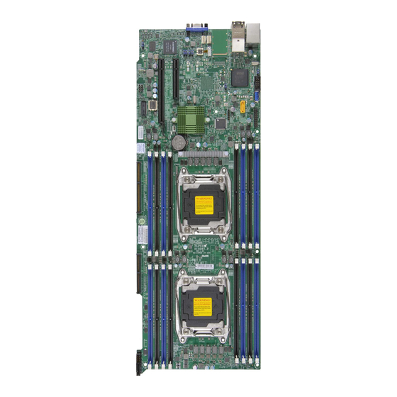
Checklist Congratulations on purchasing your computer motherboard from an acknowledged leader in the industry. Supermicro boards are designed with the utmost attention to detail to provide you with the highest standards in quality and performance. This motherboard was designed to be used with an SMCI-proprietary chassis as an integrated server platform. - Page 10 X10DRT-PS Motherboard User’s Manual Motherboard Image Note: All graphics shown in this manual were based upon the latest PCB Revision available at the time of publishing of the manual. The motherboard you've received may or may not look exactly the same as the graphics shown in this manual.
-
Page 11: Motherboard Layout
Notes: 1. For the latest CPU/Memory updates, please refer to our website at http:// www.supermicro.com/products/motherboard/ for details. 2. Use only the correct type of onboard CMOS battery as specified by the manufacturer. Do not install the onboard battery upside down to avoid... - Page 12 X10DRT-PS Motherboard User’s Manual X10DRT-PS Motherboard Quick Reference UID_LED1 JUIDB1 UID SW JUSB1 BIOS COM1 SIOM FLASH SIOM:CPU1 PCI-E 3.0 X16 JBT1 JPME2 BIOS LICENSE JSD1 JBAT1 S-SATA3 JWD1 BATTERY CPU2_VRM_HS1 CPU2 SXB1 X10DRT-PS SXB2 REV:1.00 CPU1 Notes: • See Chapter 2 for detailed information jumpers, I/O ports, connectors and ex- pansion slots.
- Page 13 Chapter 1: Overview X10DRT-PS Motherboard Jumpers Jumper Description Default Setting JBT1 Clear CMOS See Chapter 2 JPB1 Baseboard Management Controller (BMC) Pins 1-2 (Enabled) Enable JPG1 VGA Enable Pins 1-2 (Enabled) JPME2 Manufacture (ME) Mode Select Pins 1-2 (Normal) JVRM1/2 I2C Bus for VRM 1/2 1-2 BMC, 2-3:PCH JWD1 Watch Dog Timer Enable...
- Page 14 X10DRT-PS Motherboard User’s Manual Notes...
-
Page 15: Motherboard Features
ECC 2400/2133/1866 MHz memory in 16 slots Note: Memory speed support is pending on the processors installed in the system. For the latest CPU/memory updates, please refer to our website at http://www.supermicro.com/ products/motherboard. DIMM Sizes Up to 64GB @ 1.20V •... -
Page 16: Peripheral Devices
X10DRT-PS Motherboard User’s Manual I/O Devices IPMI 2.0 • IPMI 2.0 supported by the ASpeed 2400 BMC Serial (COM) Port • One (1) Fast UART 16550 connection header • Rear VGA Port Peripheral USB Devices Devices • Two (2) USB ports on the rear I/O panel (USB 3.0) Ports USB 0/1 •... - Page 17 Chapter 1: Overview LED Indicators • BMC (BaseBoard Management) LED • CPU/Overheat LED • Power/suspend-state • Fan fail LED • UID/remote UID LED • LAN Activity LED • System PECI (Platform Environment Configuration Interface) Management 2.0 support • System resource alert via SuperDoctor® 5 •...
-
Page 18: System Block Diagram
X10DRT-PS Motherboard User’s Manual #1-8 #2-8 #1-7 #2-7 #1-6 #2-6 #1-5 #2-5 #1-4 #2-4 #1-3 #2-3 #1-2 #2-2 #1-1 #2-1 9.6G DDR4 DDR4 9.6G #2 DMI2 DMI2 PCI-E X8 G3 PCI-E X16 G3 PCI-E X16 G3 PCI-E X16 PCI-E X8 mini PCI-E SIOM DMI2 6.0 Gb/S... -
Page 19: Processor And Chipset Overview
Chapter 1: Overview Processor and Chipset Overview Built upon the functionality and capability of the Intel E5-2600 (v3/v4) Series pro- cessors (Socket R3) and the Intel C612 PCH, the X10DRT-PS Series motherboard provides the best balanced solution of performance, power efficiency, and features to address the diverse needs of next-generation TwinPro server platforms. -
Page 20: Special Features
X10DRT-PS Motherboard User’s Manual Special Features Recovery from AC Power Loss The Basic I/O System (BIOS) provides a setting that determines how the system will respond when AC power is lost and then restored to the system. You can choose for the system to remain powered off (in which case you must press the power switch to turn it back on), or for it to automatically return to the power-on state. -
Page 21: Acpi Features
Chapter 1: Overview ACPI Features ACPI stands for Advanced Configuration and Power Interface. The ACPI specifica- tion defines a flexible and abstract hardware interface that provides a standard way to integrate power management features throughout a computer system, including its hardware, operating system and application software. This enables the system to automatically turn on and off peripherals such as network cards, hard disk drives and printers. -
Page 22: Advanced Power Management
The following new advanced power management features are supported by the motherboard. Intel Intelligent Power Node Manager (NM) (Available ® when the Supermicro Power Manager [SPM] is installed) The Intel Intelligent Power Node Manager (IPNM) provides your system with ® real-time thermal control and power management for maximum energy efficiency. -
Page 23: Chapter 2 Installation
The following statements are industry-standard warnings, provided to warn the user of situations which have the potential for bodily injury. Should you have questions or experience difficulty, contact Supermicro's Technical Support department for assis- tance. Only certified technicians should attempt to install or configure components. - Page 24 X10DRT-PS Motherboard User’s Manual Attention Danger d'explosion si la pile n'est pas remplacée correctement. Ne la remplacer que par une pile de type semblable ou équivalent, recommandée par le fabricant. Jeter les piles usagées conformément aux instructions du fabricant. ¡Advertencia! Existe peligro de explosión si la batería se reemplaza de manera incorrecta.
-
Page 25: Product Disposal
Chapter 2: Installation Product Disposal Warning! Ultimate disposal of this product should be handled according to all national laws and regulations. 製品の廃棄 この製品を廃棄処分する場合、 国の関係する全ての法律 ・ 条例に従い処理する必要が あり ます。 警告 本产品的废弃处理应根据所有国家的法律和规章进行。 警告 本產品的廢棄處理應根據所有國家的法律和規章進行。 Warnung Die Entsorgung dieses Produkts sollte gemäß allen Bestimmungen und Gesetzen des Landes erfolgen. -
Page 26: Static-Sensitive Devices
X10DRT-PS Motherboard User’s Manual Static-Sensitive Devices Electrostatic Discharge (ESD) can damage electronic com ponents. To avoid pos- sible damage to your motherboard, it is important to handle it very carefully. The following measures are generally sufficient to protect your equipment from ESD. Precautions •... -
Page 27: Processor And Heatsink Installation
CPU socket cap is in place and none of the socket pins are bent; otherwise, contact your retailer immediately. • Refer to the Supermicro website for updates on CPU support. Installing the LGA2011 Processor 1. There are two load levers on the LGA2011 socket. To open the socket cover, first press and release the load lever labeled 'Open 1st'. - Page 28 X10DRT-PS Motherboard User’s Manual 2. Press the second load lever labeled 'Close 1st' to release the load plate that covers the CPU socket from its locking position. Press down on Load Pull lever away from Lever 'Close 1st' the socket 3.
- Page 29 Chapter 2: Installation 4. Using your thumb and the index finger, remove the 'WARNING' plastic cap from the socket. IMPORTANT! 5. Use your thumb and index finger to hold the CPU on its edges. Align the CPU keys, which are semi-circle cutouts, against the socket keys. Socket Keys CPU Keys 6.
- Page 30 X10DRT-PS Motherboard User’s Manual 7. With the CPU inside the socket, inspect the four corners of the CPU to make sure that the CPU is properly installed. 8. Close the load plate with the CPU inside the socket. Lock the 'Close 1st' lever first, then lock the 'Open 1st' lever second.
-
Page 31: Installing A Passive Cpu Heatsink
Chapter 2: Installation Installing a Passive CPU Heatsink 1. Apply the proper amount of thermal grease to the heatsink. 2. Place the heatsink on top of the CPU so that the two mounting holes on the heatsink are aligned with those on the retention mechanism. 3. -
Page 32: Removing The Passive Heatsink
X10DRT-PS Motherboard User’s Manual Removing the Passive Heatsink Warning: We do not recommend that the CPU or the heatsink be removed. However, if you do need to remove the heatsink, please follow the instructions below to uninstall the heatsink to avoid damaging the CPU or other components. 1. -
Page 33: Installing And Removing The Memory Modules
Chapter 2: Installation Installing and Removing the Memory Modules Note: Check Supermicro's website for recommended memory modules. CAUTION Exercise extreme care when installing or removing DIMM modules to prevent any possible damage. Installing & Removing DIMMs 1. Insert the desired number of DIMMs into the memory slots, starting with P1-DIMMA1. - Page 34 Note: Memory speed support is pending on the processors installed in the system. For the latest CPU/memory updates, please refer to our website at http://www.supermicro.com/products/motherboard. Processor & Memory Module Population Configuration For memory to work properly, follow the tables below for memory installation.
- Page 35 Chapter 2: Installation Memory Support for E5-2600 (v3)-based Motherboards Speed (MT/s) Speed (MT/s); Voltage (V); Voltage (V) Slot Per Channel (SPC) & DIMM Per Channel (DPC) Ranks Per DIMM DIMM and Capacity (GB) 1 Slot Per 2 Slots Per Channel Type Data Channel...
-
Page 36: Motherboard Installation
X10DRT-PS Motherboard User’s Manual Motherboard Installation All motherboards have standard mounting holes to fit different types of chassis. Make sure that the locations of all the mounting holes for both motherboard and chassis match. Although a chassis may have both plastic and metal mounting fas- teners, metal ones are highly recommended because they ground the motherboard to the chassis. -
Page 37: Control Panel Connectors And I/O Ports
Chapter 2: Installation Control Panel Connectors and I/O Ports The I/O ports are intended to be used in SMC TwinPro servers. See the picture below for the locations of I/O ports. Back Panel Connectors and I/O Ports X10DRT-PS REV:1.00 Back Panel I/O Port Locations and Definitions 1. -
Page 38: Universal Serial Bus (Usb)
X10DRT-PS Motherboard User’s Manual Universal Serial Bus (USB) USB (3.0) 0/1 Pin Definitions Two USB 3.0 ports are located on the Pin# Definition I/O back panel (USB 0/1). (Cables are not included.) See the table on the right for pin definitions. Ground Ground 1. -
Page 39: Ipmi_Lan Ethernet Port
Chapter 2: Installation IPMI_LAN Ethernet Port An IPMI_LAN, located next to the VGA port on the I/O backpanel, provides KVM support for IPMI 2.0 interface. This LAN port is supported by the ASpeed AST2400 Baseboard Management Controller (BMC), and accepts an RJ45 type cable. (Note: Please refer to the LED Indicator Section for LAN LED information.) Video Connector A Video (VGA) connector is located on the IO backpanel. -
Page 40: Unit Identifier Switch
X10DRT-PS Motherboard User’s Manual Unit Identifier Switch UID Switches & LEDs Two Unit Identifier (UID) switches and two Description Location UID LED indicators are located on your Rear Switch SW1 (on the I/O backpanel) system. The rear UID switch (SW1) is lo- Rear UID LED UID_LED1 cated on the I/O backpanel, and the rear... -
Page 41: Front Panel Accessible Add-On Card Connector (Jf1)
X10DRT-PS motherboard. Insert an add-on card into this connector to use the functions indicated above. This connector is designed specifically for a Supermicro-proprietary add-on card. Refer to the layout below for the location of JF1. -
Page 42: Connecting Cables
X10DRT-PS Motherboard User’s Manual Connecting Cables COM Port Header COM Port Header Pin Definitions (COM1) A COM port header is located on the Pin # Definition Pin # Definition motherboard. See the table on the right for pin definitions. Ground DOM Power Connector DOM PWR Pin Definitions... -
Page 43: Tpm Header/Port 80
Chapter 2: Installation TPM Header/Port 80 TPM/Port 80 Header Pin Definitions A Trusted Platform Module/Port 80 Pin # Definition Pin # Definition header, located at JTPM1, provides TPM LCLK support and Port 80 connection. Use this LFRAME# <(KEY)> header to enhance system performance LRESET# +5V (X) and data security. -
Page 44: Jumper Settings
X10DRT-PS Motherboard User’s Manual Jumper Settings Explanation of Jumpers Connector Pins To modify the operation of the motherboard, jumpers can be used to choose between optional settings. Jumpers create shorts be- Jumper tween two pins to change the function of the connector. -
Page 45: Cmos Clear
Chapter 2: Installation CMOS Clear JBT1 is used to clear CMOS. Instead of pins, this "jumper" consists of contact pads to prevent accidental clearing of CMOS. To clear CMOS, use a metal object such as a small screwdriver to touch both pads at the same time to short the connection. Always remove the AC power cord from the system before clearing CMOS. -
Page 46: Vga Enable
X10DRT-PS Motherboard User’s Manual VGA Enable VGA Enable Jumper Settings Jumper JPG1 allows the user to enable Jumper Setting Definition or disable the onboard VGA connector. Enabled (Default) The default setting is 1-2 to enable the Disabled connection. See the table on the right for jumper settings. -
Page 47: Onboard Led Indicators
Chapter 2: Installation LAN 1/LAN 2 Onboard LED Indicators IPMI LAN IPMI_LAN LEDs Link LED Activity LED An IPMI_LAN port, supported by the ASpeed AST 2400 Baseboard Management Control- IPMI LAN IPMI LAN Link LED (Left) & ler (BMC), is located on the I/O backpanel. Activity LED (Right) (X8ST3-F) This LAN port has two LED indicators. -
Page 48: Bmc Heartbeat Led
X10DRT-PS Motherboard User’s Manual BMC Heartbeat LED BMC Heartbeat LED Status A BMC Heartbeat LED is located at Color/State Definition BMC_HB_LED1 on the motherboard. Green: BMC: Normal When this LED is blinking, BMC functions Blinking normally. See the table at right for more information. -
Page 49: Rear Uid Led
Chapter 2: Installation Rear UID LED UID LED Status The rear UID LED is located at UID_ Color/State Status LED1 on the rear of the motherboard. Blue: Blinking/On Unit Identified This LED is used in conjunction with the rear UID switch to provide easy identifi- cation of a system that might be in need of service. -
Page 50: 2-10 Sata And Sata/Pci-E 3.0 Slots
X10DRT-PS Motherboard User’s Manual 2-10 SATA and SATA/PCI-E 3.0 Slots S-SATA 0-2/CPU2_PCI-Express 3.0 x16 Slot (SXB1) A PCI-Express 3.0 x16 slot is located on SXB1. CPU2 PCE-E 3.0 x16 supports three S-SATA 3.0 (S-SATA 0-2) connections. Refer to the layout below for the location. I-SATA 0-5/CPU1_PCI-Express 3.0 x8 Slot (SXB2) CPU1_PCI-Express 3.0 x8 slot, located on SXB2, supports I-SATA 0-5 connections. -
Page 51: Sata Dom/Power
A SATA DOM (Device-on-Disk) is located at S- Pin# Signal SATA3 on the motherboard. S-SATA3 is used with a Ground Supermicro SuperDOM, which is a yellow SATA DOM SATA_TXP connector with a power pin built in, and no external SATA_TXN power supply is needed. Supermicro SuperDOM is... - Page 52 X10DRT-PS Motherboard User’s Manual Notes 2-30...
-
Page 53: Chapter 3 Troubleshooting
Chapter 3: Troubleshooting Chapter 3 Troubleshooting Troubleshooting Procedures Use the following procedures to troubleshoot your system. If you have followed all of the procedures below and still need assistance, refer to the ‘Technical Support Procedures’ and/or ‘Returning Merchandise for Service’ section(s) in this chapter. Note: Always disconnect the power cord before adding, changing or installing any hardware components. -
Page 54: System Boot Failure
X10DRT-PS Motherboard User’s Manual No Video 1. If the power is on, but you do not have video, remove all the add-on cards and cables. 2. Use the speaker to determine if any beep codes exist. Refer to Appendix A for details on beep codes. -
Page 55: Memory Errors
2. Memory support: Make sure that the memory modules are supported by test- ing the modules using memtest86 or a similar utility. Note: Refer to the product page on our website http:\\www.supermicro. com for memory and CPU support and updates. - Page 56 X10DRT-PS Motherboard User’s Manual 3. HDD support: Make sure that all hard disk drives (HDDs) work properly. Re- place the bad HDDs with good ones. 4. System cooling: Check system cooling to make sure that all heatsink fans, CPU fans and system fans work properly. Check Hardware Monitoring set- tings in BIOS to make sure that the CPU and System temperatures are within the normal range.
-
Page 57: Technical Support Procedures
Technical Support Procedures Before contacting Technical Support, please take the following steps. Also, please note that as a motherboard manufacturer, Supermicro also sells motherboards through its channels, so it is best to first check with your distributor or reseller for troubleshooting services. -
Page 58: Battery Removal And Installation
• Distributors: For immediate assistance, please have your account number ready when placing a call to our technical support department. We can be reached by e-mail at support@supermicro.com. Battery Removal and Installation Battery Removal To remove the onboard battery, follow the steps below: Proper Battery Disposal Warning: Please handle used batteries carefully. -
Page 59: Frequently Asked Questions
Note: The SPI BIOS chip used on this motherboard cannot be removed. Send your motherboard back to our RMA Department at Supermicro for repair. For BIOS Recovery instructions, please refer to the AMI BIOS Recovery Instructions posted at http://www.supermicro.com. -
Page 60: Returning Merchandise For Service
Shipping and handling charges will be applied for all orders that must be mailed when service is complete. For faster service, You can also request a RMA authorization online (http://www.supermicro.com/RmaForm/). This warranty only covers normal consumer use and does not cover damages in- curred in shipping or from failure due to the alternation, misuse, abuse or improper maintenance of products. -
Page 61: Chapter 4 Bios
When an option is selected in the left frame, it is highlighted in white. Often a text message will accompany it. Note: the AMI BIOS has default text messages built in. Supermicro retains the option to include, omit, or change any of these text messages. -
Page 62: Main Setup
Flashing the wrong BIOS can cause irreparable damage to the system. In no event shall Supermicro be liable for direct, indirect, special, incidental, or consequential damages arising from a BIOS update. If you have to update the BIOS, do not shut down or reset the system while the BIOS is updating to avoid possible boot failure. - Page 63 MM/DD/YYYY format. The time is entered in HH:MM:SS format. Note: The time is in the 24-hour format. For example, 5:30 P.M. appears as 17:30:00. Supermicro X10DRT-PS BIOS Version: This item displays the version of the BIOS ROM used in the system.
-
Page 64: Advanced Setup Configurations
X10DRT-PS Motherboard User’s Manual Advanced Setup Configurations Use the arrow keys to select Advanced setup and press <Enter> to access the submenu items: Warning: Take Caution when changing the Advanced settings. An incorrect value, an improper DRAM frequency, or a wrong BIOS setting may cause the system to malfunction. -
Page 65: Power Configuration
Chapter 4: AMI BIOS Wait For 'F1' If Error Select Enabled to force the system to wait until the <F1> key is pressed when an error occurs. The options are Disabled and Enabled. INT19 Trap Response Interrupt 19 is the software interrupt that handles the boot disk function. When this item is set to Immediate, the ROM BIOS of the host adaptors will "capture"... -
Page 66: Cpu Configuration
X10DRT-PS Motherboard User’s Manual CPU Configuration This submenu displays the following CPU information as detected by the BIOS. It also allows the user to configure CPU settings. • Processor Socket • Processor ID • Processor Frequency • Processor Max Ratio •... - Page 67 Chapter 4: AMI BIOS PPIN Control Select Unlock/Enable to use the Protected-Processor Inventory Number (PPIN) control in the system. The options are Unlock/Enable and Unlock/Disable. Hardware Prefetcher (Available when supported by the CPU) If set to Enable, the hardware prefetcher will prefetch streams of data and instruc- tions from the main memory to the L2 cache to improve CPU performance.
-
Page 68: Advanced Power Management Configuration
X10DRT-PS Motherboard User’s Manual Intel Virtualization Technology Select Enable to use Intel's Virtualization Technology for Direct I/O VT-d support by reporting the I/O device assignments to the VMM (Virtual Machine Monitor) through the DMAR ACPI tables. This feature offers fully-protected I/O resource sharing across Intel platforms, providing greater reliability, security and availability in networking and data-sharing. - Page 69 Chapter 4: AMI BIOS *If the option is set to Custom, the following items will display: CPU P State Control (Available when Power Technology is set to Custom) EIST (P-states) Select Enable to support EIST (Enhanced Intel SpeedStep Technology), which will allow the system to automatically adjust processor voltage and core fre- quency to reduce power consumption and heat dissipation.
-
Page 70: Chipset Configuration
X10DRT-PS Motherboard User’s Manual CPU C State Control (Available when Power Technology is set to Custom) Package C State limit Use this item to set the limit on the C-State package register. The options are C0/1 state, C2 state, C6 (non-Retention) state, and C6 (Retention) state. CPU C3 Report Select Enable to allow the BIOS to report the CPU C3 state (ACPI C2) to the operating system. -
Page 71: Iio Configuration
Chapter 4: AMI BIOS IIO Configuration EV DFX (Device Function On-Hide) Features When this item is set to Enable, the EV_DFX Lock Bits that are located on a processor will always remain clear during electric tuning. The options are Dis- able and Enable. - Page 72 X10DRT-PS Motherboard User’s Manual IIO1 IOU1 Non-Posted Prefetch Select Enable to enable a selected non-posted IOU0 drive to be used for CPU prefetching. The options are Enable and Disable. IIO1 IOU2 Non-Posted Prefetch Select Enable to enable a selected non-posted IOU0 drive to be used for CPU prefetching.
- Page 73 Chapter 4: AMI BIOS IIO2 IOU1 Non-Posted Prefetch Select Enable to enable a selected non-posted IOU0 drive to be used for CPU prefetching. The options are Enable and Disable. IIO2 IOU2 Non-Posted Prefetch Select Enable to enable a selected non-posted IOU0 drive to be used for CPU prefetching.
- Page 74 X10DRT-PS Motherboard User’s Manual QPI (Quick Path Interconnect) Configuration QPI General Configuration QPI Status The following information will display: • Number of CPU • Number of II0 • Current QPI Link Speed • Current QPI Link Frequency • QPI Global MMIO Low Base/Limit •...
-
Page 75: Memory Configuration
Chapter 4: AMI BIOS Isoc Mode Select Enable for Isochronous support to meet QoS (Quality of Service) require- ments. This feature is especially important for Intel's Virtualization Technology. The options are Enable and Disable. Memory Configuration This submenu allows the user to configure Integrated Memory Controller (IMC) settings. -
Page 76: South Bridge Configuration
X10DRT-PS Motherboard User’s Manual Memory RAS (Reliability_Availability_Serviceability) Configuration Use this submenu to configure the following Memory RAS settings. RAS Mode When Independent is selected, all memory modules operate independently. When Mirror is selected, the motherboard maintains two identical copies of all data in memory for data backup. - Page 77 Chapter 4: AMI BIOS • USB Module Version • USB Controllers • USB Devices Legacy USB Support Select Enabled to support onboard legacy USB devices. Select Auto to disable legacy support when there are no legacy USB devices present. Select Disabled to have all USB devices available for EFI applications only.
-
Page 78: Sata Configuration
X10DRT-PS Motherboard User’s Manual XHCI Pre-Boot Driver Select Enabled to load Intel XHCI pre-boot driver. The settings are Enabled and Disabled. SATA Configuration When this submenu is selected, AMI BIOS automatically detects the presence of the SATA devices that are supported by the Intel PCH chip and displays the fol- lowing items: SATA Controller This item enables or disables the onboard SATA controller supported by the Intel... - Page 79 Chapter 4: AMI BIOS Port 0 ~ Port 5 Spin Up Device On an edge detect from 0 to 1, set this item to allow the PCH to initialize the device. The options are Enabled and Disabled. Port 0 ~ Port 5 SATA Device Type Use this item to specify if the SATA port specified by the user should be con- nected to a Solid State drive or a Hard Disk Drive.
-
Page 80: Ssata Configuration
X10DRT-PS Motherboard User’s Manual sSATA Configuration When this submenu is selected, AMI BIOS automatically detects the presence of the s-SATA devices that are supported by the PCH-sSATA controller and displays the following items: sSATA Controller This item enables or disables the onboard SATA controller supported by the Intel PCH chip. - Page 81 Chapter 4: AMI BIOS Port 0 ~ Port 3 sSATA Device Type Use this item to specify if the sSATA port specified by the user should be con- nected to a Solid State drive or a Hard Disk Drive. The options are Hard Disk Drive and Solid State Drive.
- Page 82 X10DRT-PS Motherboard User’s Manual sSATA Port 0 ~ Port 3 Spin Up Device On an edge detect from 0 to 1, set this item to allow the PCH to start a COMRE- SET initialization to the device. The options are Enabled and Disabled. Port 0 ~ Port 3 sSATA Device Type Use this item to specify if the sSATA port specified by the user should be con- nected to a Solid State drive or a Hard Disk Drive.
- Page 83 Chapter 4: AMI BIOS PCI PERR/SERR Support Select Enabled to support PERR (PCI/PCI-E Parity Error)/SERR (System Error) runtime error reporting for a PCI/PCI-E slot. The options are Enabled and Disabled. Above 4G Decoding (Available if the system supports 64-bit PCI decoding) Select Enabled to decode a PCI device that supports 64-bit in the space above 4G Address.
- Page 84 X10DRT-PS Motherboard User’s Manual CPU2 Slot1 (RSC-R1UTP) PCI-E 3.0x16 OPROM/CPU2 Slot2 (RSC-P6) PCI-E 3.0x8 OPROM/CPU1 SAS PCI-E 3.0x8 OPROM/CPU2 SXB1 3.0x 16 OPROM Select Enabled to enable Option ROM support to boot the computer using a de- vice installed on the slot specified by the user. The options are Disabled, Legacy, and EFI.
-
Page 85: Super Io Configuration
Chapter 4: AMI BIOS Super IO Configuration Super IO Chip AST2400 Super IO Chip AST2400 Serial Port 1 Configuration/Serial Port 2 Configuration Serial Port 1/Serial Port 2 Select Enabled to enable the onboard serial port specified by the user. The options are Enabled and Disabled. -
Page 86: Com1 Console Redirection Settings
X10DRT-PS Motherboard User’s Manual COM1 Console Redirection Settings Terminal Type Use this item to select the target terminal emulation type for Console Redirec- tion. Select VT100 to use the ASCII Character set. Select VT100+ to add color and function key support. Select ANSI to use the Extended ASCII Character set. Select VT-UTF8 to use UTF8 encoding to map Unicode characters into one or more bytes. - Page 87 Chapter 4: AMI BIOS Recorder Mode Select Enabled to capture the data displayed on a terminal and send it as text messages to a remote server. The options are Disabled and Enabled. Resolution 100x31 Select Enabled for extended-terminal resolution support. The options are Dis- abled and Enabled.
- Page 88 X10DRT-PS Motherboard User’s Manual Bits Per second Use this feature to set the transmission speed for a serial port used in Console Redirection. Make sure that the same speed is used in the host computer and the client computer. A lower transmission speed may be required for long and busy lines.
- Page 89 Chapter 4: AMI BIOS Resolution 100x31 Select Enabled for extended-terminal resolution support. The options are Dis- abled and Enabled. Legacy OS Redirection Resolution Use this feature to select the number of rows and columns used in Console Redirection for legacy OS support. The options are 80x24 and 80x25. Putty KeyPad This feature selects Function Keys and KeyPad settings for Putty, which is a terminal emulator designed for the Windows OS.
-
Page 90: Acpi Settings
X10DRT-PS Motherboard User’s Manual Terminal Type Use this feature to select the target terminal emulation type for Console Redirec- tion. Select VT100 to use the ASCII character set. Select VT100+ to add color and function key support. Select ANSI to use the extended ASCII character set. Select VT-UTF8 to use UTF8 encoding to map Unicode characters into one or more bytes. - Page 91 Chapter 4: AMI BIOS Trusted Computing (Available when a TPM device is detected by the BIOS) How to Enable TPM in the BIOS The steps below describe the proper procedure on how to enable the TPM in the BIOS. This process is necessary to activate support in the system before you can start using the TPM.
- Page 92 X10DRT-PS Motherboard User’s Manual 5. From the screen as shown above, select "Security Device Support" and press <Enter>. From the option field, select [Enabled] and press <Enter>. 6. Scroll down to select "TPM State" and press <Enter>. From the option field, select [Enabled] and press <Enter>.
-
Page 93: Iscsi Configuration
(EV DFX is under "IIO Configuration" in the "Chipset/North Bridge" submenu on Page 4-10.) Note: For more information on TPM, please refer to the TPM manual at http://www.supermicro.com/manuals/other/. iSCSI Configuration This item displays iSCSI configuration information. iSCSI Initiator Name Use this item to enter the name of the iSCSI Initiator, which is a unique name used in the world. -
Page 94: Event Logs
X10DRT-PS Motherboard User’s Manual Add an Attempt Delete Attempts Change Attempt Order Event Logs This submenu allows the user to configure Event Log settings. Change SMBIOS Event Log Settings This feature allows the user to configure SMBIOS Event settings. Enabling/Disabling Options SMBIOS Event Log Select Enabled to enable SMBIOS (System Management BIOS) Event Logging... -
Page 95: View Smbios Event Log
Chapter 4: AMI BIOS Erasing Settings Erase Event Log Select Yes to erase all error events in the SMBIOS (System Management BIOS) log before an event logging is initialized at bootup. The options are No, Yes, Next reset, and Yes, every reset. When Log is Full Select Erase Immediately to immediately erase all errors in the SMBIOS event log when the event log is full. -
Page 96: Ipmi
X10DRT-PS Motherboard User’s Manual IPMI This submenu allows the user to configure IPMI settings. The following items will be displayed: • BMC (Baseboard Management Controller) Firmware Revision • IPMI Status System Event Log Enabling/Disabling Options SEL Components Select Enabled to enable all system event logging support at bootup. The options are Enabled and Disabled. -
Page 97: Bmc Network Configuration
Chapter 4: AMI BIOS When SEL is Full This feature allows the user to determine what the AMI BIOS should do when the system event log is full. Select Erase Immediately to erase all events in the log when the system event log is full. The options are Do Nothing and Erase Immediately. Note: After making changes on a setting, be sure to reboot the system for the changes to take effect. -
Page 98: Security Settings
X10DRT-PS Motherboard User’s Manual VLAN (Available when Update IPMI LAN Configuration is set to Yes) Select Enabled to enable onboard LAN connections to be used for Intel Virtualization Technology. The options are Enable and Disable. When this option is set to Enable, the following item will display. -
Page 99: Secure Boot Menu
Chapter 4: AMI BIOS User Password (Available after an Administrator Password is entered) Use this feature to set the user password which is required to enter the BIOS setup utility. The length of the password should be from 3 characters to 20 char- acters long. -
Page 100: Boot Settings
X10DRT-PS Motherboard User’s Manual Platform Key (PK) This feature allows the user to configure and save platform key settings. Key Exchange Key This feature allows the user to configure and save Key-Exchange-Key settings. Authorized Signatures This feature allows the user to set and save authorized signatures and grant access to those whose names appear on the list. -
Page 101: Boot Configuration
Chapter 4: AMI BIOS Boot Configuration Setup Prompt Timeout Use this item to enter the number of seconds for the system to wait for the setup activation key before entering the Setup utility. Enter 65535 (0xFFFF) to wait indefinitely. The default setting is 1. Boot Mode Select Use this item to select the type of device to be used for system boot. -
Page 102: Save & Exit
X10DRT-PS Motherboard User’s Manual Delete Boot Option Use this item to select a boot device to delete from the boot priority list. Delete Boot Option Select the target boot device to delete from the boot priority list. Network Drive BBS Priorities •... - Page 103 Chapter 4: AMI BIOS Discard Changes and Exit Select this item to exit from the BIOS setup without making any permanent changes to the system configuration, and reboot the computer. Save Changes and Reset When you have completed the system configuration changes, select this item to leave the BIOS setup utility and reboot the computer for the new system configura- tion parameters to take effect.
- Page 104 X10DRT-PS Motherboard User’s Manual Notes 4-44...
-
Page 105: Appendix A Software Installation Instructions
To install these programs, click the icons to the right of these items. Note: To install the Windows OS, please refer to the instructions posted on our website at http://www.supermicro.com/support/manuals/. Driver/Tool Installation Display Screen Note 1: Click the icons showing a hand writing on the paper to view the readme files for each item. -
Page 106: Configuring Superdoctor 5
X10DRT-PS Motherboard User’s Manual A-2 Configuring SuperDoctor 5 The Supermicro SuperDoctor® 5 is a hardware monitoring program that functions in a command-line or web-based interface in the Windows and Linux operating sys- tems. The program monitors system health information such as CPU temperatures, system voltages, system power consumption, fan speed, and provides alerts via email or Simple Network Management Protocol (SNMP). -
Page 107: Appendix B Uefi Bios Recovery Instructions
Flashing the wrong BIOS can cause irreparable damage to the system. In no event shall Supermicro be liable for direct, indirect, special, incidental, or consequential damages arising from a BIOS update. If you need to update the BIOS, do not shut down or reset the system while the BIOS is updating to avoid possible boot failure. - Page 108 "\" directory of a USB device or a writeable CD/DVD. Note: If you cannot locate the "Super.ROM" file in your driver disk, visit our website at www.supermicro.com to download the BIOS image into a USB flash device and rename it "Super.ROM" for BIOS recovery use.
- Page 109 Appendix B: UEFI BIOS Recovery 4. After locating the new BIOS binary image, the system will enter the BIOS recovery menu as shown below. Note: At this point, you may decide if you want to start with BIOS recovery. If you decide to proceed with BIOS recovery, follow the procedures below. 5.
- Page 110 X10DRT-PS User’s Manual 6. After the process of BIOS recovery is completed, press any key to reboot the system. 7. Using a different system, extract the BIOS package into a bootable USB flash drive. 8. When a DOS prompt appears, enter FLASH.BAT BIOSname.### at the prompt.
- Page 111 (Disclaimer Continued) The products sold by Supermicro are not intended for and will not be used in life support systems, medical equipment, nuclear facilities or systems, aircraft, aircraft devices, aircraft/emergency communication devices or other critical systems whose failure to perform be reasonably expected to result in significant injury or loss of life or catastrophic property damage.
Need help?
Do you have a question about the X10DRT-PT and is the answer not in the manual?
Questions and answers