
Related Manuals for AXIOMTEK wm5201


Summary of Contents for AXIOMTEK wm5201
- Page 1 MANO881 Series ® Intel Socket 1150 Core i7/ i5/ i3/ ® Celeron Processor Mini ITX Board with HDMI/ VGA/ LVDS User’s Manual...
- Page 2 Axiomtek does not make any commitment to update the information in this manual. Axiomtek reserves the right to change or revise this document and/or product at any time without notice. No part of this document may be reproduced, stored in a retrieval system, or transmitted, in any form or by any means, electronic, mechanical, photocopying, recording, or otherwise, without the prior written permission of Axiomtek Co., Ltd.
-
Page 3: Esd Precautions
Wear a wrist-grounding strap, available from most electronic component stores, when handling boards and components. Trademarks Acknowledgments Axiomtek is a trademark of Axiomtek Co., Ltd. ® Windows is a trademark of Microsoft Corporation. AMI is a trademark of American Megatrend Inc. -
Page 4: Table Of Contents
Table of Contents Disclaimers ...................... ii ESD Precautions ..................... iii Chapter 1 Introduction ..........1 Features ....................2 Specifications ..................2 Utilities Supported ................. 3 Chapter 2 Board and Pin Assignments ....5 Board Layout ..................5 Rear Panel I/O ..................7 Jumper Settings .................. - Page 5 Expansion Slots (PCI-Express and mSATA Slots) ....... 21 Installing an Expansion Card ............... 21 Chapter 4 Hardware Description ......23 Microprocessors .................. 23 BIOS....................23 System Memory .................. 23 I/O Port Address Map ................24 Interrupt Controller (IRQ) Map ............. 26 Memory Map ..................
- Page 6 This page is intentionally left blank.
-
Page 7: Chapter 1 Introduction
MANO881 Series All-In-One Mini ITX Board Chapter 1 Introduction ® The MANO881 is a Mini ITX board based on the 4 Generation Intel Core i7 / i5 / i3 / ® Celeron processors (codename: Haswell) in LGA1150 socket. This motherboard integrates ®... -
Page 8: Features
MANO881 Series All-In-One Mini ITX Board Features ® ® Core™ i7/ i5/ i3/ Celeron LGA1150 Socket 4 Generation Intel processors (codename: Haswell) 2 DDR3 1600/1333MHz max. up to 16GB memory capacity PCI-Express x16 Gen. 2 supported 1 mSATA supported ... -
Page 9: Utilities Supported
MANO881 Series All-In-One Mini ITX Board Serial ATA Two SATA 3.0 ports (6Gb/s). Two SATA 2.0 ports (3Gb/s). Audio HD codec audio as MIC-in/line-out with Realtek ALC662. Expansion Slot One PCI-Express x16 Gen. 2. ... - Page 10 MANO881 Series All-In-One Mini ITX Board This page is intentionally left blank. Introduction...
-
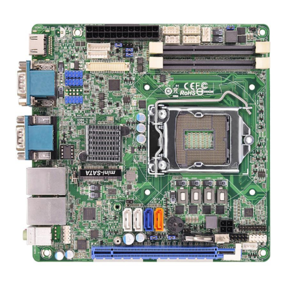
Page 11: Board And Pin Assignments
MANO881 Series All-In-One Mini ITX Board Chapter 2 Board and Pin Assignments Board Layout Top View Board and Pin Assignments... - Page 12 MANO881 Series All-In-One Mini ITX Board 1 : Backlight Power Connector (BLT_PWR1) 2 : Backlight Volume Control Connector (BLT_VOL1) 3 : 24-pin ATX Power Input Connector (ATXPWR1) 4 : Panel Power Selection (PNL_PWR1) 5 : Backlight Power Selection (BKT_PWR1) 6 : PWM Level Selection (BLT_PWM1) 7 : PS/2 Keyboard and Mouse Connector (PS2_KB_MS1) 8 : RS-232 Port Headers (COM4, COM5, COM6) 9 : 4-pin +12V CPU Fan Connector (CPU_FAN1)
-
Page 13: Rear Panel I/O
MANO881 Series All-In-One Mini ITX Board Rear Panel I/O Jumper Settings Jumper is a small component consisting of jumper clip and jumper pins. Install jumper clip on 2 jumper pins to close. And remove jumper clip from 2 jumper pins to open. The following illustration shows how to set up jumper. -
Page 14: Restore Bios Optimal Defaults (Clrcmos1)
MANO881 Series All-In-One Mini ITX Board 2.3.1 Restore BIOS Optimal Defaults (CLRCMOS1) CLRCMOS1 allows you to clear the data in CMOS. To clear and reset the system parameters to default setup, please turn off the computer and unplug the power cord from the power supply. -
Page 15: Headers And Connectors
MANO881 Series All-In-One Mini ITX Board Headers and Connectors Signals go to other parts of the system through headers and connectors. Loose or improper connection might cause problems, please make sure all headers and connectors are properly and firmly connected. Here is a summary table showing headers and connectors on the hardware. -
Page 16: Rear Panel Connectors
MANO881 Series All-In-One Mini ITX Board 2.4.1 Rear Panel Connectors COM Port (COM1)* USB 2.0 Ports (T:USB3, B:USB2) COM Port (COM3)* USB 3.0 Ports (T:USB1, B:USB0) LAN RJ-45 Port (LAN1)** D-Sub VGA Port (VGA1) LAN RJ-45 Port (LAN2)** COM Port (COM2)* Line-out (Lime) HDMI Port (HDMI1) Microphone (Pink) -
Page 17: Backlight Power Connector (Blt_Pwr1)
MANO881 Series All-In-One Mini ITX Board 2.4.2 Backlight Power Connector (BLT_PWR1) The backlight power interface is available through this connector. Signal BL CTL BL EN LCD_BLT_VCC LCD_BLT_VCC 2.4.3 Backlight Volume Control Connector (BLT_VOL1) The backlight volume control interface is available through this connector. Signal GPIO_VOL_UP GPIO_VOL_DW... -
Page 18: Atx Power Input Connectors (Atxpwr1 And Con1)
MANO881 Series All-In-One Mini ITX Board 2.4.4 ATX Power Input Connectors (ATXPWR1 and CON1) Steady and sufficient power can be supplied to all components on the motherboard by connecting power connector. Please make sure all components and devices are properly installed before connecting the power connector. External power supply plug fits into this connector in only one orientation. -
Page 19: Ps/2 Keyboard And Mouse Connector (Ps2_Kb_Ms1)
MANO881 Series All-In-One Mini ITX Board 2.4.5 PS/2 Keyboard and Mouse Connector (PS2_KB_MS1) This is an interface for PS/2 keyboard and mouse. Signal KBCLK KBDATA MSDATA MSCLK 2.4.6 RS-232 Port Wafers (COM4~COM6) COM4/COM5/COM6: Signal Signal No Power/+5V/+12V 2.4.7 Fan Connectors (CPU_FAN1 and CHA_FAN1) Fans are always needed for cooling down CPU and system temperature. -
Page 20: Chassis Intrusion Headers (Ci1~Ci2)
MANO881 Series All-In-One Mini ITX Board The CHA_FAN1 is for chassis fan interface. Please connect the fan cable to the fan connector and match the black wire to the ground pin. Signal +12V CHA_FAN_SPEED FAN_SPEED_CONTROL 2.4.8 Chassis Intrusion Headers (CI1~CI2) This motherboard supports CASE OPEN detection feature that detects if the chassis cover has been removed. -
Page 21: System Panel Header (Panel1)
MANO881 Series All-In-One Mini ITX Board 2.4.9 System Panel Header (PANEL1) This header accommodates several system front panel functions. Signal Signal HDLED+ PLED+ HDLED- PLED- PWRBTN# RESET# DUMMY Connect the power switch, reset switch and system status indicator on the chassis to this header according to the pin assignments below. -
Page 22: Digital I/O Header (Jgpio1)
MANO881 Series All-In-One Mini ITX Board 2.4.11 Digital I/O Header (JGPIO1) The JGPIO1 is for digital I/O interface. Signal Signal SIO_GP24 SIO_GP20 SIO_GP25 SIO_GP21 SIO_GP26 SIO_GP22 SIO_GP27 SIO_GP23 JGPIO_PWR1 2.4.12 SATA Connectors (SATA_0~SATA_1 and SATA_4~SATA_5) These two Serial ATA 3.0 (SATA 3.0) connectors support SATA data cables for internal storage devices. -
Page 23: Usb 2.0 Headers (Usb4_5, Usb8_9 And Usb10_11)
MANO881 Series All-In-One Mini ITX Board 2.4.14 USB 2.0 Headers (USB4_5, USB8_9 and USB10_11) There are three USB 2.0 headers on this motherboard. Each USB 2.0 header can support two USB 2.0 ports. Signal Signal USB DX- USB DY- USB DX+ USB DY+ 2.4.15 LVDS Panel Connector (LVDS1) - Page 24 MANO881 Series All-In-One Mini ITX Board This page is intentionally left blank. Board and Pin Assignments...
-
Page 25: Chapter 3 Hardware Installation
MANO881 Series All-In-One Mini ITX Board Chapter 3 Hardware Installation This is a Mini ITX form factor (6.7”x6.7”, 17.0x17.0 cm) motherboard. Before you install the motherboard, study the configuration of your chassis to ensure that the motherboard fits into it. Make sure to unplug the power cord before installing or removing the motherboard. -
Page 26: Installing Memory Modules (So-Dimm)
MANO881 Series All-In-One Mini ITX Board Installing Memory Modules (SO-DIMM) This motherboard provides two 204-pin DDR3 (Double Data Rate 3) SO-DIMM sockets. It is not allowed to install a DDR or DDR2 memory module into DDR3 socket; otherwise, this motherboard and SO-DIMM may be damaged. Note Please make sure to disconnect power supply before adding or removing SO-DIMMs or the system components. -
Page 27: Expansion Slots (Pci-Express And Msata Slots)
MANO881 Series All-In-One Mini ITX Board Expansion Slots (PCI-Express and mSATA Slots) There are 1 PCI-Express and 1 mSATA slots on this motherboard. PCI-Express slots: PCIE1 (PCI-Express x16 slot; Blue) is used for PCI-Express x16 lane width graphics cards. mini-SATA (mSATA slot) is used for mSATA cards. Installing an Expansion Card Step 1. - Page 28 MANO881 Series All-In-One Mini ITX Board This page is intentionally left blank. Hardware Installation...
-
Page 29: Chapter 4 Hardware Description
MANO881 Series All-In-One Mini ITX Board Chapter 4 Hardware Description Microprocessors ® ® The MANO881 Series supports Intel Core i7/ i5/ i3/ Celeron processors, which enable ® ® ® your system to operate under Windows 7, Windows 8, Windows 8.1 and Linux environments. -
Page 30: I/O Port Address Map
MANO881 Series All-In-One Mini ITX Board I/O Port Address Map ® ® The Intel Core i7/ i5/ i3/ Celeron processors communicate via I/O ports. Total 1KB port addresses are available for assigning to other devices via I/O expansion cards. Hardware Description... - Page 31 MANO881 Series All-In-One Mini ITX Board Hardware Description...
-
Page 32: Interrupt Controller (Irq) Map
MANO881 Series All-In-One Mini ITX Board Interrupt Controller (IRQ) Map The interrupt controller (IRQ) mapping list is shown as follows: Hardware Description... - Page 33 MANO881 Series All-In-One Mini ITX Board Hardware Description...
- Page 34 MANO881 Series All-In-One Mini ITX Board Hardware Description...
- Page 35 MANO881 Series All-In-One Mini ITX Board Hardware Description...
-
Page 36: Memory Map
MANO881 Series All-In-One Mini ITX Board Memory Map The memory mapping list is shown as follows: Hardware Description... -
Page 37: Ami Bios Setup Utility
MANO881 Series All-In-One Mini ITX Board Chapter 5 AMI BIOS Setup Utility The AMI UEFI BIOS provides users with a built-in setup program to modify basic system configuration. All configured parameters are stored in a flash chip to save the setup information whenever the power is turned off. -
Page 38: Menu Bar
MANO881 Series All-In-One Mini ITX Board Menu Bar The top of the screen has a menu bar with the following selections: Menu Bar Description Main To set up the system time/date information. Advanced To set up the advanced BIOS features. H/W Monitor To display current hardware status. - Page 39 MANO881 Series All-In-One Mini ITX Board Please check the following table for the function description of each navigation key. Hot Keys Description Left/Right The Left and Right <Arrow> keys allow you to select a setup screen. The Up and Down <Arrow> keys allow you to select a setup screen or ...
-
Page 40: Main Menu
MANO881 Series All-In-One Mini ITX Board Main Menu When you first enter the setup utility, you will enter the Main setup screen. You can always return to the Main setup screen by selecting the Main tab. System Time/Date can be set up as described below. -
Page 41: Advanced Menu
MANO881 Series All-In-One Mini ITX Board Advanced Menu The Advanced menu also allows users to set configuration of the CPU and other system devices. You can select any of the items in the left frame of the screen to go to the sub menus: ►... - Page 42 MANO881 Series All-In-One Mini ITX Board Instant Flash Instant Flash is a UEFI flash utility embedded in Flash ROM. This convenient UEFI update tool allows you to update system UEFI without entering operating systems first like MS-DOS or ® Windows .
- Page 43 MANO881 Series All-In-One Mini ITX Board CPU Configuration Active Processor Cores Select the number of cores to enable in each processor package. CPU C States Support Enable CPU C States Support for power saving. It is recommended to keep C3, C6 and C7 all enabled for better power saving.
- Page 44 MANO881 Series All-In-One Mini ITX Board Intel SpeedStep Technology ® ® ’s new power saving technology. Processors can Intel SpeedStep technology is Intel switch between multiple frequencies and voltage points to enable power saving. The default value is Enabled. Configuration options are Enabled and Disabled. If you install ®...
- Page 45 MANO881 Series All-In-One Mini ITX Board Chipset Configuration DRAM Frequency If Auto is selected, the motherboard will detect the memory module(s) inserted and assign the appropriate frequency automatically. Primary Graphics Adapter This allows you to select Onboard or PCI Express as the boot graphic adapter priority. The default value is PCI Express.
- Page 46 MANO881 Series All-In-One Mini ITX Board Render Standby Use this to enable or disable Render Standby by Internal Graphics Device. The default value is Enabled. Onboard HD Audio Select Auto, Enabled or Disabled for the onboard HD Audio feature. If you select Auto, the onboard HD Audio will be disabled when PCI Sound Card is plugged.
- Page 47 MANO881 Series All-In-One Mini ITX Board Storage Configuration SATA Controller(s) Use this item to enable or disable the SATA Controller feature. SATA Mode Selection Use this to select SATA mode. Configuration options are IDE Mode, AHCI Mode and RAID Mode.
- Page 48 MANO881 Series All-In-One Mini ITX Board Intel(R) Smart Connect Technology Intel(R) Smart Connect Technology Use this item to enable or disable Intel(R) Smart Connect Technology. Intel(R) Smart Connect Technology keeps your e-mail and social networks, such as Twitter, Facebook, etc.
- Page 49 MANO881 Series All-In-One Mini ITX Board Super IO Configuration COM1 Configuration Use this to set parameters of COM1. COM1 port type options are RS232, RS422 or RS485. COM2 Configuration Use this to set parameters of COM2. COM2 port type options are RS232, RS422 or RS485.
- Page 50 MANO881 Series All-In-One Mini ITX Board ACPI Configuration Suspend to RAM Use this item to select whether to auto-detect or disable the Suspend-to-RAM feature. Select Auto will enable this feature if the OS supports it. Check Ready Bit Use this item to enable or disable the feature Check Ready Bit. ACPI HPET Table Use this item to enable or disable ACPI HPET Table.
- Page 51 MANO881 Series All-In-One Mini ITX Board USB Mouse Power On Use this item to enable or disable USB Mouse to power on the system. USB Configuration USB Controller Use this item to enable or disable the use of USB controller. Intel USB 3.0 Mode ®...
- Page 52 MANO881 Series All-In-One Mini ITX Board Voltage Configuration DRAM Voltage Use this to select DRAM Voltage. The default value is 1.50V. AMI BIOS Setup Utility...
-
Page 53: H/W Monitor Menu
MANO881 Series All-In-One Mini ITX Board H/W Monitor Menu In this section, it allows you to monitor the status of the hardware on your system, including the parameters of the CPU temperature, motherboard temperature, CPU fan speed, chassis fan speed, and the critical voltage. CPU_FAN1 Setting This allows you to set CPU fan 1’s speed. -
Page 54: Boot Menu
MANO881 Series All-In-One Mini ITX Board Boot Menu In this section, it will display the available devices on your system for you to configure the boot settings and the boot priority. Boot From Onboard LAN Use this item to enable or disable the Boot From Onboard LAN feature. Setup Prompt Timeout This shows the number of seconds to wait for setup activation key. - Page 55 MANO881 Series All-In-One Mini ITX Board Enable to launch the Compatibility Support Module. Please do not disable unless you’re ® running a WHCK test. If you are using Windows 8 64-bit and all of your devices support UEFI, you may also disable CSM for faster boot speed. Launch PXE OpROM Policy Select UEFI only to run those that support UEFI option ROM only.
-
Page 56: Security Menu
MANO881 Series All-In-One Mini ITX Board Security Menu In this section, you may set, change or clear the supervisor/user password for the system. Secure Boot Use this to enable or disable Secure Boot. The default value is Disabled. AMI BIOS Setup Utility... -
Page 57: Exit Menu
MANO881 Series All-In-One Mini ITX Board Exit Menu Save Changes and Exit When you select this option, it will pop-out the following message, “Save configuration changes and exit setup?”. Select OK to save the changes and exit the UEFI setup utility. Discard Changes and Exit When you select this option, it will pop-out the following message, “Discard changes and exit setup?”.
Need help?
Do you have a question about the wm5201 and is the answer not in the manual?
Questions and answers