
Related Manuals for AXIOMTEK SHB111


Summary of Contents for AXIOMTEK SHB111
- Page 1 SHB111 Arrandale Full-Size SBC User’s Manual SHB111 ™ ® ® Intel QM57 PCH with Intel Core i7 / i5 / i3 Processor / Intel® Celeron® Processor PICMG 1.3 Industrial Motheroard User’s Manual...
- Page 2 Axiomtek does not make any commitment to update the information in this manual. Axiomtek reserves the right to change or revise this document and/or product at any time without notice. No part of this document may be reproduced, stored in a retrieval...
-
Page 3: Esd Precautions
Wear a wrist-grounding strap, available from most electronic component stores, when handling boards and components. Trademarks Acknowledgments Axiomtek is a trademark of Axiomtek Co., Ltd. ® Windows is a trademark of Microsoft Corporation. AMI are trademarks of American Megatrend Inc. -
Page 4: Table Of Contents
SHB111 Arrandale Full-Size SBC User’s Manual Table of Contents ESD Precautions .................. iii CHAPTER 1 ......................1 INTRODUCTION ....................1 1.1 Specifications..............2 1.2 Utilities Supported ............. 4 1.3 I/O Bracket ................5 CHAPTER 2 ......................6 JUMPERS AND CONNECTORS................. 6 ... - Page 5 SHB111 Arrandale Full-Size SBC User’s Manual CHAPTER 3 ......................26 HARDWARE DESCRIPTION ................26 3.1 Microprocessors .............. 26 3.2 BIOS .................. 26 3.3 System Memory..............26 3.4 I/O Port Address Map............27 3.5 Interrupt Controller (IRQ) Map ........28 ...
-
Page 7: Chapter 1
SHB111 Arrandale Full-Size SBC User’s Manual CHAPTER 1 INTRODUCTION The SHB111 PICMG 1.3 full-size Single Board Computer supports rPGA988 socket for Intel® Core™ i7 Mobile Processor, Intel® Core™ i5 Mobile Processor and Intel® Core™ i3 Mobile Processor and Intel® Celeron® Processor with 32nm technology and Transfer Rate 800/1066 MHz. -
Page 8: Specifications
(COM1) and one port for RS-232/422/485 with 10- pin, 2.54-pitch box-header (COM2) Floppy controller: one 34-pin, 2.54-pitch box-header supports two drives (1.44MB for each) USB Interface Ten USB ports compliant with USB Spec. Rev. 2.0 (Ten ports on SHB111, Four ports to SHB connector-C golden fingers) Introduction... - Page 9 SHB111 Arrandale Full-Size SBC User’s Manual Onboard Graphics ® Intel Arrandale integrated Graphics Processing Unit (GPU) processors which goes with Intel® QM57 chipset with LVDS, VGA, DisplayPort (co-lay woth VGA). ® Memory Size -- Intel DVMT supported Resolution -- VGA output up to a resolution of 2048x1536...
-
Page 10: Utilities Supported
SHB111 Arrandale Full-Size SBC User’s Manual Utilities Supported ® Intel Chipset Drivers ® Intel Graphics Drivers Ethernet Utility and Drivers HD Audio Drivers RAID Utility iAMT Utility and Drivers TPM Utility NOTE By the limitation of QM57, the PCIe x4 slot and the PCIe x1 slot can’t work at the same time with the same BIOS version. -
Page 11: I/O Bracket
SHB111 Arrandale Full-Size SBC User’s Manual I/O Bracket I/O Bracket for VGA Output I/O Bracket for DisplayPort Output Introduction... -
Page 12: Chapter 2
SHB111 Arrandale Full-Size SBC User’s Manual CHAPTER 2 JUMPERS AND CONNECTORS Board Dimensions Jumpers and Connectors... -
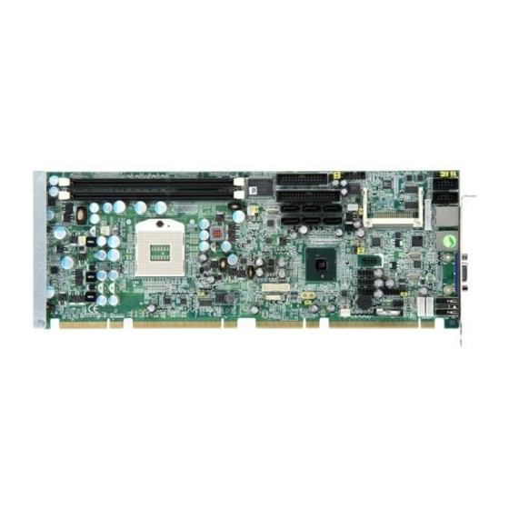
Page 13: Board Layout
SHB111 Arrandale Full-Size SBC User’s Manual Board Layout Jumpers and Connectors... -
Page 14: Jumper Settings
SHB111 Arrandale Full-Size SBC User’s Manual Jumper Settings Proper jumper settings configure the SHB111 to meet your application purpose. We are herewith listing a summary table of all jumpers and default settings for onboard devices, respectively. Jumper Default Setting Jumper Setting... -
Page 15: Audio Amplifier Selection (Jp5)
SHB111 Arrandale Full-Size SBC User’s Manual Audio Amplifier Selection (JP5) Description Function Jumper Setting Disable Audio (Default) Amplifier Enable CF Voltage Selection (JP7) Description Function Jumper Setting 3.3V CF Power (Default) Jumpers and Connectors... -
Page 16: Clear Me Setting (Jp8)
SHB111 Arrandale Full-Size SBC User’s Manual Clear ME Setting (JP8) You may need to use this jumper is to clear the ME setting if incorrect BIOS settings. Description Function Jumper Setting Normal ME Clear (Default) Clear ME LVDS Voltage Selection (JP11) -
Page 17: Connectors
SHB111 Arrandale Full-Size SBC User’s Manual Connectors Connectors connect this board with other parts of the system. Loose or improper connection might cause problems. Make sure all connectors are properly and firmly connected. Here is a summary table shows you all connectors on the board. - Page 18 SHB111 Arrandale Full-Size SBC User’s Manual Jumpers and Connectors...
-
Page 19: Hd Audio Connector (Cn1)
SHB111 Arrandale Full-Size SBC User’s Manual HD Audio Connector (CN1) CN1 is a 10pin-header connector commonly used for the audio. Signal Signal MIC-IN 2 GND Line In L 4 GND Line In R 6 GND Audio Out L 8 GND... -
Page 20: Floppy Connector (Cn3)
SHB111 Arrandale Full-Size SBC User’s Manual Signal Signal 15 Data 6 16 GND 17 Data 7 18 GND 19 Acknowledge# 20 GND 21 Busy 22 GND 23 Paper Empty# 24 GND 25 Printer Select 26 GND Floppy Connector (CN3) The board provides a 34-pin header type connector, CN3, supporting up to two floppy drives. -
Page 21: Lan2 External Led Connector (Cn4)
SHB111 Arrandale Full-Size SBC User’s Manual LAN2 External LED Connector (CN4) Signal + 3.3V_SBY LINK_ACT 100, Low Active + 3.3V_SBY 1000, Low Active LAN1 External LED Connector (CN5) Signal + 3.3V_SBY LINK_ACT 100, Low Active + 3.3V_SBY 1000, Low Active... -
Page 22: Displayport Connector (Cn7)
SHB111 Arrandale Full-Size SBC User’s Manual DisplayPort Connector (CN7) CN7 is a Standard Display Port Connector co-layout with CN6. Signal DPB_LANE0 DPB_LANE0# DPB_LANE1 DPB_LANE1# DPB_LANE2 DPB_LANE2# DPB_LANE3 DPB_LANE3# DPB_AUX DPB_AUX# DPB_HPDE N.C. 3.3V Jumpers and Connectors... -
Page 23: Lvds Connector (Cn8)
SHB111 Arrandale Full-Size SBC User’s Manual LVDS Connector (CN8) CN8 is JST 40pin connector for the LVDS flat panel. Signal Signal VCCM VCCM VCCM VCCM VCCM VCCM N.C. N.C. Channel B D3- Channel B D0- Channel B D3+ Channel B D0+... -
Page 24: Front Panel Connector (Cn9)
SHB111 Arrandale Full-Size SBC User’s Manual Front Panel Connector (CN9) Power LED This 3-pin connector denoted as Pin 1 and Pin 5 connects the system power LED indicator to such a switch on the case. Pin 1 is assigned as +, and Pin 5 as -. The Power LED lights up when the system is powered ON. -
Page 25: Lvds Inverter Connector (Cn10)
SHB111 Arrandale Full-Size SBC User’s Manual LVDS Inverter Connector (CN10) The 7-pin inverter connector on the SHB111 is with Hirose connector. The matching connector is strongly recommended to use Hirose DF13-7S-1.25C. Signal ENABLE CF Connector (CN11) The board is equipped with a CompactFlash... - Page 26 SHB111 Arrandale Full-Size SBC User’s Manual Address 6 CSEL# Signal Signal Address 5 VS2# Address 4 RESET# Address 3 IORDY# Address 2 DMAREQ Address 1 DMAACK- Address 0 DASP# Data 0 PDIAG# Data 1 Data 8 Data 2 Data 9...
-
Page 27: Com1/2 Connetor (Cn12/Cn13)
SHB111 Arrandale Full-Size SBC User’s Manual COM1/2 Connetor (CN12/CN13) The serial interface for the board consists of COM1 port supports RS232 and COM2 supports RS232/422/485. Signal Signal Data Carrier Data Set Ready Detect (DCD) (DSR) Receive Data Request to Send... -
Page 28: External Keyboard/Mouse Connectors (Cn16/Cn17)
SHB111 Arrandale Full-Size SBC User’s Manual External Keyboard/Mouse Connectors (CN16/CN17) The board provides the Keyboard (CN16)/ Mouse (CN17) interface with a 5-pin connector. Clock Data No Connection Power SATA0~5 Connectors (CN18/CN19/CN20/CN21/CN22/CN23) These SATA connectors are for high-speed SATA interface ports and they can be connected to hard disk devices. -
Page 29: Smbus Connector (Cn24)
SHB111 Arrandale Full-Size SBC User’s Manual SMBUS Connector (CN24) Connector SMBUS1 is for SMBUS interface support. Signal CLOCK DATA USB Connectors (CN25/CN26/CN27/CN28) The 10-pin standard Universal Serial Bus (USB) connectors, CN25/CN26/CN27/CN28, on this board are for installing versatile USB interface peripherals. -
Page 30: Usb Connectors (Cn29/Cn30)
USB Power USB8- USB9- USB8+ USB9+ USB Connectors (CN29/CN30) The SHB111 Series features Universal Serial Bus (USB) connectors, compliant with USB 2.0 (480Mbps) that can be adapted to any USB peripherals, such as monitor, keyboard and mouse. Signal CN29 USB POWER... -
Page 31: Auxiliary & System Fan Connectors (Cn31/Cn33)
SHB111 Arrandale Full-Size SBC User’s Manual Auxiliary & System Fan Connectors (CN31/CN33) You can connect the system cooling fan cable to CN31/CN33 for system cooling fan power. Signal CN31 CN33 +12V Sensor CPU Fan Connector (CN32) A CPU fan is always needed for cooling CPU heat. The CPU fan connector CN32 provides power to the CPU fan. -
Page 32: Chapter 3
Make sure all correct settings are arranged for your installed microprocessor to prevent the CPU from damages. BIOS The SHB111 Series uses AMI Plug and Play BIOS with a single 64Mbit SPI Flash. System Memory The SHB111 Series supports four 240-pin DDR3 DIMM sockets for a maximum memory of 8GB DDR3 SDRAMs. -
Page 33: I/O Port Address Map
SHB111 Arrandale Full-Size SBC User’s Manual I/O Port Address Map ® ™ ™ ™ ® The Intel Core i7 / Core i5 / Core i3 / Celeron processors can communicate via I/O ports. There are total 1KB port addresses available for assignment to other devices via I/O expansion cards. -
Page 34: Interrupt Controller (Irq) Map
SHB111 Arrandale Full-Size SBC User’s Manual Interrupt Controller (IRQ) Map The SHB111 Series is a 100% PC compatible control board. It consists of 16 interrupt request lines, and four out of them can be programmable. The mapping list of the 16 interrupt request lines is shown as the following table. -
Page 35: Chapter 4
SHB111 Arrandale Full-Size SBC User’s Manual CHAPTER 4 AMI BIOS UTILITY This chapter provides users with detailed description how to set up basic system configuration through the AMIBIOS8 BIOS setup utility. Starting To enter the setup screens, follow the steps below: Turn on the computer and press the <F2>... - Page 36 SHB111 Arrandale Full-Size SBC User’s Manual The Left <Arrow> keys allow you to select a setup Left/Right screen. The Up and Down <Arrow> keys allow you to select a Up/Down setup screen or sub-screen. The Plus and Minus <Arrow> keys allow you to change +−...
-
Page 37: Main Menu
SHB111 Arrandale Full-Size SBC User’s Manual Main Menu When you first enter the Setup Utility, you will enter the Main setup screen. You can always return to the Main setup screen by selecting the Main tab. There are two Main Setup options. They are described in this section. -
Page 38: Advanced Menu
SHB111 Arrandale Full-Size SBC User’s Manual Advanced Menu Launch PXE OpROM Use this item to enable or disable the Boot ROM function of the onboard LAN chip when the system boots up. Launch Storage OpROM This item can set enable or disable the storage device option ROM with CF device. - Page 39 SHB111 Arrandale Full-Size SBC User’s Manual ACPI Settings You can use this screen to select options for the ACPI Configuration, and change the value of the selected option. A description of the selected item appears on the right side of the screen.
- Page 40 SHB111 Arrandale Full-Size SBC User’s Manual ACPI Sleep State Allow you to select the Advanced Configuration and Power Interface (ACPI) state to be used for system suspend. Here are the options for your selection, S1 (CPU Stop Clock), S3 (Suspend to RAM) and Suspend Disable...
- Page 41 SHB111 Arrandale Full-Size SBC User’s Manual Trusted Computing You can use this screen to select options for the Trusted Computing, and change the value of the selected option. A description of the selected item appears on the right side of the screen.
- Page 42 SHB111 Arrandale Full-Size SBC User’s Manual CPU Configuration This screen shows the CPU Configuration, and you can change the value of the selected option. Hyper-threading This item can set enable or disable for support Hyper-threading Technology. Active Processor Cores This feature controls the number of cores to enable in each processor package.
- Page 43 SHB111 Arrandale Full-Size SBC User’s Manual Intel Virtualization Technology Allows a hardware platform to run multiple operating systems separately and simultaneously, enabling one system to virtually function as several systems. SATA Configuration You can use this screen to select options for the SATA Configuration, and change the value of the selected option.
- Page 44 SHB111 Arrandale Full-Size SBC User’s Manual Serial-ATA Controller 1 Use this item to control the onboard SATA controller. Here are the options for your selection, Enhanced and Disabled. Intel IGD SWSCI OpRegion The Intel IGD SWSCI OpRegion allows users to change the integrated graphic device settings.
- Page 45 SHB111 Arrandale Full-Size SBC User’s Manual LCD Panel Type Allow you to select resolution of LCD panel. USB Configuration You can use this screen to select options for the USB Configuration, and change the value of the selected option. A description of the selected item appears on the right side of the screen.
- Page 46 SHB111 Arrandale Full-Size SBC User’s Manual Super IO Configuration You can use this screen to select options for the Super IO Configuration, and change the value of the selected option. A description of the selected item appears on the right side of the screen.
- Page 47 SHB111 Arrandale Full-Size SBC User’s Manual H/W Monitor This screen shows the Hardware Health Configuration, and a description of the selected item appears on the right side of the screen. Smart Fan Function This item can enable or disable the Smart Fan function.
- Page 48 SHB111 Arrandale Full-Size SBC User’s Manual AMT Configuration You can use this screen to select options for the Intel AMT Configuration, and change the value of the selected option. A description of the selected item appears on the right side of the screen.
-
Page 49: Chipset Menu
SHB111 Arrandale Full-Size SBC User’s Manual Chipset Menu The Chipset menu allows users to change the advanced chipset settings. You can select any of the items in the left frame of the screen to go to the sub menus: North Bridge... - Page 50 SHB111 Arrandale Full-Size SBC User’s Manual North Bridge Initiate Graphic Adapter When using multiple graphics cards, this item can select which graphics controller to be the primary display device during boot. Graphics Turbo IMON Current Use this item to set Graphics Turbo IMON Current form 14 to 31.
- Page 51 SHB111 Arrandale Full-Size SBC User’s Manual PCI Express Compliance Mode Use this item to set PCI Express Compliance Testing Mode. The default setting is Disable. PCI Express Port This item is a toggle to enable or disable the PCI Express port.
- Page 52 SHB111 Arrandale Full-Size SBC User’s Manual SMBus Controller Use this item to set System Management Bus Mode. The default setting is Enable. GbE Controller This item allows you to enabled or disabled Intel® WG82577LM LAN. Wake on LAN from S5 This item specifies whether the system will be awakened from the S5 power.
- Page 53 SHB111 Arrandale Full-Size SBC User’s Manual Me Subsystem It is strongly recommended that you do not modify these options unless you are an advanced user. AMI BIOS Utility...
-
Page 54: Boot Menu
SHB111 Arrandale Full-Size SBC User’s Manual Boot Menu The Boot menu allows users to change boot options of the system. You can select any of the items in the left frame of the screen to go to the sub menus:... - Page 55 SHB111 Arrandale Full-Size SBC User’s Manual Quite Boot Use this item to enable or disable the Quite Boot state. The default setting is Disable. Fast Boot Use this item to enable or disable the Fast Boot state. The default setting is Disable.
- Page 56 SHB111 Arrandale Full-Size SBC User’s Manual Hard Drive BBS Priorities The Hard Drive BBS Priorities screen specifies the boot device priority sequence from the available devices. AMI BIOS Utility...
-
Page 57: Security Menu
SHB111 Arrandale Full-Size SBC User’s Manual Security Menu The Security menu allows users to change the security settings for the system. Administrator Password This item indicates whether an administrator password has been set. If the password has been installed, Installed displays. -
Page 58: Save & Exit Menu
SHB111 Arrandale Full-Size SBC User’s Manual Save & Exit Menu The Save & Exit menu allows users to load your system configuration with optimal or failsafe default values. Save Changes and Exit When you have completed the system configuration changes, select this option to leave Setup and return to Main Menu. - Page 59 SHB111 Arrandale Full-Size SBC User’s Manual Save Changes and Reset When you have completed the system configuration changes, select this option to leave Setup and reboot the computer so the new system configuration parameters can take effect. Select Save Changes and Reset from the Save &...
-
Page 60: Appendix A
SHB111 Arrandale Full-Size SBC User’s Manual APPENDIX A WATCHDOG TIMER Watchdog Timer Setting After the system stops working for a while, it can be auto-reset by the Watchdog Timer. The integrated Watchdog Timer can be set up in the system reset mode by program. - Page 61 SHB111 Arrandale Full-Size SBC User’s Manual IF to disable WDT :O 2E 30 O 2F 00 ; Can be disable at any time N=00 M= 00h: Time-out Disable 01h: Time-out occurs after 1 second 02h: Time-out occurs after 2 second 03h: Time-out occurs after 3 second ………………………........
-
Page 62: Appendix B
SHB111 Arrandale Full-Size SBC User’s Manual APPENDIX B PCI IRQ ROUTING PICMG PCI IRQ Routing Device Slot PCI Slot 0 BCDA PCI Slot 1 CDAB PCI Slot 2 DABC PCI Slot 3 ABCD PCI IRQ Routing... -
Page 63: Appendix C
SHB111 Arrandale Full-Size SBC User’s Manual APPENDIX C CONFIGURING SATA FOR RAID FUNCTION Configuring SATA Hard Drive(s) for RAID Function ® (Controller: Intel QM57 ) Please follow up the steps below to configure SATA hard drive(s): (1) Install SATA hard drive(s) in your system. - Page 64 SHB111 Arrandale Full-Size SBC User’s Manual (2)-1-1 Turn on your system, and then press the F2 button to enter BIOS Setup during running POST (Power-On Self Test). If you want to create RAID, just go to the Advanced Settings menu/SATA configuration, select the SATA Mode, and press <Enter>...
- Page 65 SHB111 Arrandale Full-Size SBC User’s Manual (2)-1-2 A list of options appears, please select RAID Mode. Configuring SATA for RAID Function...
- Page 66 SHB111 Arrandale Full-Size SBC User’s Manual (2)-2 Set CDROM for Boot Option #1 under the Boot Configurations menu to boot CD-ROM after system restarts. Configuring SATA for RAID Function...
- Page 67 SHB111 Arrandale Full-Size SBC User’s Manual (2)-3 Save and exit the BIOS Setup. (3) Configuring RAID by the RAID BIOS Enter the RAID BIOS setup utility to configure a RAID array. Skip this step and proceed to Section 4 if you do not want to create a RAID.
- Page 68 SHB111 Arrandale Full-Size SBC User’s Manual (3)-2 After you press <CTRL+ I>, the Create RAID Volume screen will appear. If you want to create a RAID array, select the Create RAID Volume option in the Main Menu and press ENTER.
- Page 69 SHB111 Arrandale Full-Size SBC User’s Manual (3)-3-1 After entering the CREATE VOLUME MENU screen, you can type the disk array name with 1~16 letters (letters cannot be special characters) in the item “Name”. Configuring SATA for RAID Function...
- Page 70 SHB111 Arrandale Full-Size SBC User’s Manual (3)-3-2 When finished, press ENTER to select a RAID level. There are three RAID levels, RAID0, RAID1 and RAID5 & RAID10. Select a RAID level and press ENTER. Configuring SATA for RAID Function...
- Page 71 SHB111 Arrandale Full-Size SBC User’s Manual (3)-3 Set the stripe block size. The KB is the standard unit of stripe block size. The stripe block size can be 4KB to 128KB. After the setting, press ENTER for the array capacity.
- Page 72 SHB111 Arrandale Full-Size SBC User’s Manual (3)-5 When prompting the confirmation, press “Y“ to create this volume, or “N“ to cancel the creation. After the creation is completed, you can see detailed information about the RAID Array in the DISK/VOLUME INFORMATION section, including RAID mode, disk block size, disk name, and disk capacity, etc.
- Page 73 SHB111 Arrandale Full-Size SBC User’s Manual Delete RAID Volume If you want to delete a RAID volume, select the Delete RAID Volume option in Main Menu. Press ENTER and follow on-screen instructions. Please press [ESC] to exit the RAID BIOS utility.
- Page 74 SHB111 Arrandale Full-Size SBC User’s Manual (4) Making a SATA Driver Disk To install the operating system onto a serial ATA hard disk successfully, you need to install the SATA controller driver during the OS installation. Without the driver, the hard disk may not be recognized during the Windows setup process.
- Page 75 SHB111 Arrandale Full-Size SBC User’s Manual (5) Installing the SATA controller driver during the OS installation Now, the SATA driver disk is ready, and BIOS settings configured, you can proceed to install Windows 2000/XP onto your SATA hard drive using the SATA driver. Here is an example for Windows XP installation.
- Page 76 SHB111 Arrandale Full-Size SBC User’s Manual (5)-2 When you see the screen below, insert the floppy disk containing the SATA driver and press “S”. Configuring SATA for RAID Function...
- Page 77 SHB111 Arrandale Full-Size SBC User’s Manual (5)-3 If the Setup correctly recognizes the driver of the floppy disk, a controller menu will appear below. Use the ARROW keys to select Intel® ICH8M-E/ICH9M-E/PCHM SATA RAID Controller and press ENTER. Then it will begin to load the SATA driver from the floppy disk.
-
Page 78: Appendix D
SHB111 Arrandale Full-Size SBC User’s Manual APPENDIX D Intel iAMT SETTINGS ® ® ® The Intel Active Management Technology (Intel iAMT) has decreased a major barrier to IT efficiency that uses built-in platform capabilities and popular third-party management and security applications to allow IT a better discovering, healing, and protection their networked computing assets. -
Page 79: Set & Change Password
SHB111 Arrandale Full-Size SBC User’s Manual Set & Change Password 1. You will be asked to set a password when first log in. The default password is ‘admin’. Intel Iamt Settings... - Page 80 SHB111 Arrandale Full-Size SBC User’s Manual 2. You will be asked to change the password before setting ME. 3. You must confirm your new password while revising. The new password must contain: (example:!!11qqQQ) (default value) Eight characters One upper case...
-
Page 81: Intel ® Iamt Web Console
SHB111 Arrandale Full-Size SBC User’s Manual ® D.3 Intel iAMT Web Console From a web browser, please type http ://( IP ADDRESS):16992, ® which connects to Intel iAMT Web. Example: http://10.1.40.214:16992 To log on, you will be required to type in username and password for access to the Web. - Page 82 SHB111 Arrandale Full-Size SBC User’s Manual Enter the iAMT Web. Click Remote Control, and select commands on the right side. 5. When you have finished using the iAMT Web console, close the Web browser. Intel Iamt Settings...
-
Page 83: Picmg V1.3 Interface Definition
SHB111 Arrandale Full-Size SBC User’s Manual APPENDIX E PICMG v1.3 INTERFACE DEFINITION x16 PCIe Connector A x16 PCIe Connector C Side B Side A Side B Side A 1 N.C 1 USB0P 2 GND 2 USB0N 3 N.C 3 GND USB1P 4 N.C... - Page 84 SHB111 Arrandale Full-Size SBC User’s Manual Mechanical Key 29 REFCLK0+ 29 N.C 30 REFCLK0- 30 N.C 31 GND REFCLK1+ 31 N.C 32 RSVD REFCLK1- 32 N.C 33 REFCLK2+ 33 N.C 34 REFCLK2- 34 N.C 35 GND REFCLK3+ 35 N.C 36 RSVD...
- Page 85 SHB111 Arrandale Full-Size SBC User’s Manual Mechanical Key 64 GND a_PERn4 64 GND 65 a_PETp5 65 GND 66 a_PETn5 66 GND 67 GND a_PERp5 67 GND 68 GND a_PERn5 68 GND 69 a_PETp6 69 GND 70 a_PETn6 70 GND 71 GND...
- Page 86 SHB111 Arrandale Full-Size SBC User’s Manual Mechanical Key 12 GND 12 CLKC CLKD 13 a_PETp10 13 GND +3.3V 14 a_PETn10 14 CLKA CLKB 15 GND a_PERp10 15 +3.3V 16 GND a_PERn10 16 AD31 17 a_PETp11 17 AD29 +3.3V 18 a_PETn11 18 N.C...
- Page 87 SHB111 Arrandale Full-Size SBC User’s Manual 47 +12V +12V 47 GND AD02 48 +12V +12V 48 AD03 AD01 49 +12V +12V 49 AD00 Note Please contact your vendor to get the backplane design guide if it’s required. The backplane design guide is NDA required.
Need help?
Do you have a question about the SHB111 and is the answer not in the manual?
Questions and answers