
Related Manuals for AXIOMTEK MANO861


Summary of Contents for AXIOMTEK MANO861
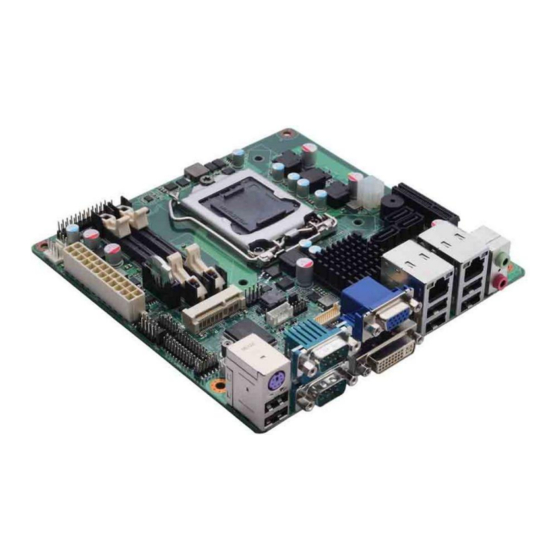
- Page 1 MANO861 ® Intel LGA1155 Socket Supports ® 22nm / 32nm Intel Xeon E3-1275 / ® E3-1225 / Intel Core i7 / Core i5 / ® ® Core i3 / Pentium / Celeron Mini ITX Motherboard User’s Manual...
-
Page 2: Disclaimers
Axiomtek does not make any commitment to update the information in this manual. Axiomtek reserves the right to change or revise this document and/or product at any time without notice. No part of this document may be reproduced, stored in a retrieval system, or transmitted, in any form or by any means, electronic, mechanical, photocopying, recording, or otherwise, without the prior written permission of Axiomtek Co., Ltd. -
Page 3: Esd Precautions
Wear a wrist-grounding strap, available from most electronic component stores, when handling boards and components. Trademarks Acknowledgments Axiomtek is a trademark of Axiomtek Co., Ltd. ® Windows is a trademark of Microsoft Corporation. AMI is a trademark of American Megatrend Inc. -
Page 4: Conventions Used In This Manual
Conventions Used in This Manual To make sure that you perform certain tasks properly, take note of the following symbols used throughout this manual. Information to prevent injury to yourself when trying to complete a task. Warning Information to prevent damage to the components when trying to complete a task. -
Page 5: Table Of Contents
Table of Contents Disclaimers ..................... ii ESD Precautions ................... iii Conventions Used in This Manual ............... iv Chapter 1 Introduction ..........1 Features ....................1 Specifications ..................2 Utilities Supported ................3 Block Diagram ..................4 Chapter 2 Board and Pin Assignments ....5 Board Layout .................. - Page 6 3.1.2 Screw Holes ....................17 Central Processing Unit (CPU) ............18 3.2.1 Installing the CPU ..................19 3.2.2 Installing the CPU Heatsink and Fan ............21 System Memory ................. 22 3.3.1 Overview ....................22 3.3.2 Memory Configurations ................23 3.3.3 Installing a SO-DIMM ................
-
Page 7: Chapter 1 Introduction
MANO861 Mini ITX Board Chapter 1 Introduction ® ® The MANO861 supports latest Intel Desktop LGA1155 CPU-socket interface processor. Intel ® ® LGA1155 socket supports 22nm/32nm Intel Xeon E3-1275 / E3-1225 / Intel Core i7 / ® ® Core i5 / Core... -
Page 8: Specifications
MANO861 Mini ITX Board Specifications ® Intel Xeon E3-1275 processor. ® Intel Xeon E3-1225 processor. ® Intel Core i7 processor. ® Intel Core i7 processor. ® Intel Core i5 processor. ® Intel Core i3 processor. -
Page 9: Utilities Supported
MANO861 Mini ITX Board Watchdog Timer 1~255 seconds; up to 256 levels. Power Management ACPI (Advanced Configuration and Power Interface). Form Factor Mini ITX form factor. All specifications and images are subject to change without notice. -
Page 10: Block Diagram
MANO861 Mini ITX Board Block Diagram Introduction... -
Page 11: Board And Pin Assignments
MANO861 Mini ITX Board Chapter 2 Board and Pin Assignments Board Layout Rear Panel I/O Board and Pin Assignments... -
Page 12: Jumper Settings
And remove jumper clip from 2 jumper pins to open. The following illustration shows how to set up jumper. Before applying power to MANO861 Series, please make sure all of the jumpers are in factory default position. Below you can find a summary table and onboard default settings. -
Page 13: Clear Cmos (Jcmos1)
MANO861 Mini ITX Board 2.3.1 Clear CMOS (JCMOS1) This jumper allows you to clear the Real Time Clock (RTC) RAM in CMOS. You can clear the CMOS memory of date, time, and system setup parameters by erasing the CMOS RTC RAM data. The onboard button cell battery powers the RAM data in CMOS, which includes system setup information such as system passwords. -
Page 14: Connectors
MANO861 Mini ITX Board Connectors Signals go to other parts of the system through connectors. Loose or improper connection might cause problems, please make sure all connectors are properly and firmly connected. Here is a summary table which shows all connectors on the hardware. -
Page 15: Rear Panel Connectors
MANO861 Mini ITX Board 2.4.1 Rear Panel Connectors PS/2 port (purple). This port is for a PS/2 keyboard and mouse. USB 2.0 ports 5 and 6. These two 4-pin Universal Serial Bus (USB) ports are available for connecting USB 2.0 devices. -
Page 16: Com Connectors (Com34 And Com56)
MANO861 Mini ITX Board System fan interface is available through SYS_FAN1, see table below. Signal SYSFAN1_VCC(PWM) SYSFAN1_IO Do not forget to connect the fan cables to the fan connectors. Insufficient air flow inside the system may damage the motherboard components. -
Page 17: Front Panel Connector (F_Panel1)
MANO861 Mini ITX Board 2.4.5 Front Panel Connector (F_PANEL1) This connector is for a chassis-mounted front panel. The functions are described as follows. Signal HDDLED+ POWERLED+- HDDLED- POWERLED- PWSWITCH RESET ATX Power Button/Soft-off Button (Pin 6-8 PWRBT) This 2-pin connector is for the system power button. Pressing the power button turns the system on or puts the system in sleep or soft-off mode depending on the BIOS settings. -
Page 18: Power Connectors (Eatxpwr And Atx12V)
MANO861 Mini ITX Board 2.4.6 Power Connectors (EATXPWR and ATX12V) Both connectors are for ATX power supply plugs. The power supply plugs are designed to fit these connectors in only one orientation. Find the proper orientation and push down firmly until the connectors completely fit. -
Page 19: Internal Audio Connector (Fpaud1)
MANO861 Mini ITX Board 2.4.7 Internal Audio Connector (FPAUD1) This connector is for a chassis-mounted front panel audio I/O module that supports either HD Audio or legacy AC ‘97 (optional) audio standard. Connect one end of the front panel audio I/O module cable to this connector. -
Page 20: Lcd Inverter Connector (Jbkl)
MANO861 Mini ITX Board 2.4.9 LCD Inverter Connector (JBKL) The connector is for the control of internal LVDS brightness. Signal +12V BL_EN BRIGHT1 2.4.10 Serial ATA Connectors (SATA1~SATA3) These connectors support SATA 2.0 and are for the Serial ATA signal cables for Serial ATA hard disk drives. -
Page 21: Selectcom Connector (Selectcom)
MANO861 Mini ITX Board 2.4.12 SelectCOM Connector (SelectCOM) Select COM for RS-232/422/485. Signal Signal UART1_RXD COM1_485_RXD UART1_RXD COM1_422_RXD UART1_RXD COM1_232_RXD COM1_BUF_DCD# COM1_BUF_TXD COM1_DCD# COM1_TXD COM1_TXD422- COM1_RXD422+ COM1_BUF_RXD COM1_BUF_DTR# COM1_RXD COM1_DTR# COM1_TXD422+ COM1_RXD422- 2.4.13 SPI Connector (SPI1) Is a point-to-point interface standard, which allows network equipment designers to... -
Page 22: Lpt Connector (Lpt)
MANO861 Mini ITX Board 2.4.15 LPT Connector (LPT) Signal Signal STB# AFD# DATA0 ERR# DATA1 INIT# DATA2 SLIN# DATA3 DATA4 DATA5 DATA6 DATA7 ACK# BUSY SLCT Board and Pin Assignments... -
Page 23: Chapter 3 Hardware Installation
MANO861 Mini ITX Board Chapter 3 Hardware Installation Take note of the following precautions before you install motherboard components or change any motherboard settings. Unplug the power cord from the wall socket before touching any component. Use a grounded wrist strap or touch a safely grounded object or a metal... -
Page 24: Central Processing Unit (Cpu)
Axiomtek will shoulder the cost of repair only if the damage is shipment/transit-related. Keep the cap after installing the motherboard. Axiomtek will process Return Merchandise Authorization (RMA) requests only if the motherboard comes with the cap on the LGA1155 socket. -
Page 25: Installing The Cpu
MANO861 Mini ITX Board 3.2.1 Installing the CPU Locate the CPU socket on the motherboard. Before installing the CPU, make sure that the socket box is facing towards you and the load lever is on your left. Caution Separate CPU cooler and its base first with screw driver. - Page 26 MANO861 Mini ITX Board Position the CPU over the socket, making sure that the gold triangle is the same side as CPU socket triangle. CPU socket triangle Gold triangle Lock and unlock CPU. The CPU fits in only one correct orientation. DO NOT force the CPU into...
-
Page 27: Installing The Cpu Heatsink And Fan
MANO861 Mini ITX Board 3.2.2 Installing the CPU Heatsink and Fan Place the heatsink base on the relative bottom of motherboard. Place the heatsink assembly on the top of the CPU, making sure that the four fasteners match the holes on the motherboard. -
Page 28: System Memory
MANO861 Mini ITX Board System Memory 3.3.1 Overview The motherboard comes with two 204-pin Double Data Rate 3 (DDR3) Small Outline Dual Inline Memory Modules (SO-DIMM) sockets. A DDR3 module has the same physical dimensions as a DDR SO-DIMM but has a 204-pin footprint compared to the 204-pin DDR2 DIMM. -
Page 29: Memory Configurations
MANO861 Mini ITX Board 3.3.2 Memory Configurations You may install 1GB, 2GB, and 4GB unbuffered ECC or non-ECC DDR3 SO-DIMMs into the SO-DIMM sockets using the memory configurations in this section. IF you installed four 1GB memory modules, the system may detect less than 3GB of total memory because of address space allocation for other critical functions. - Page 30 MANO861 Mini ITX Board Align a SO-DIMM on the socket such that the notch on the SO-DIMM matches the break on the socket. DDR3 SO-DIMM notch Unlocked retaining clip Firmly insert the SO-DIMM into the socket until the retaining clips snap back in place and the SO-DIMM is properly seated.
-
Page 31: Removing A So-Dimm
MANO861 Mini ITX Board 3.3.4 Removing a SO-DIMM Simultaneously press the retaining clips downward to unlock the SO-DIMM. Remove the SO-DIMM from the socket. Unlocked retaining clip Support the SO-DIMM lightly with your fingers when pressing the retaining clips. The SO-DIMM might get damaged when it flips out with extra force. -
Page 32: Configuring An Expansion Card
MANO861 Mini ITX Board 3.4.2 Configuring an Expansion Card After installing the expansion card, configure it by adjusting the software settings. Turn on the system and change the necessary BIOS settings, if any. See Chapter 5 for information on BIOS setup. -
Page 33: Chapter 4 Hardware Description
Make sure all correct settings are arranged for your installed microprocessor to prevent the CPU from damages. BIOS The MANO861 Series uses AMI Plug and Play BIOS with a single 32Mbit SPI Flash. System Memory The MANO861 Series supports two 204-pin DDR3 SO-DIMM sockets for a maximum memory of 16GB DDR3 SDRAMs. -
Page 34: I/O Port Address Map
MANO861 Mini ITX Board I/O Port Address Map ® ® ® The Intel Xeon E3-1275 / E3-1225 / Intel Core i7 / Core i5 / Core i3 / Pentium ® Celeron processors communicate via I/O ports. Total 1KB port addresses are available for assigning to other devices via I/O expansion cards. - Page 35 MANO861 Mini ITX Board Hardware Description...
-
Page 36: Interrupt Controller (Irq) Map
MANO861 Mini ITX Board Interrupt Controller (IRQ) Map The interrupt controller (IRQ) mapping list is shown as follows: Hardware Description... - Page 37 MANO861 Mini ITX Board Hardware Description...
- Page 38 MANO861 Mini ITX Board Hardware Description...
-
Page 39: Memory Map
MANO861 Mini ITX Board Memory Map The memory mapping list is shown as follows: Hardware Description... - Page 40 MANO861 Mini ITX Board This page is intentionally left blank. Hardware Description...
-
Page 41: Ami Bios Setup Utility
MANO861 Mini ITX Board Chapter 5 AMI BIOS Setup Utility The AMI UEFI BIOS provides users with a built-in setup program to modify basic system configuration. All configured parameters are stored in a flash chip to save the setup information whenever the power is turned off. - Page 42 MANO861 Mini ITX Board Hot Keys Description Left/Right The Left and Right <Arrow> keys allow you to select a setup screen. The Up and Down <Arrow> keys allow you to select a setup screen or Up/Down sub-screen. The Plus and Minus <Arrow> keys allow you to change the field value of a +...
-
Page 43: Main Menu
MANO861 Mini ITX Board Main Menu When you first enter the setup utility, you will enter the Main setup screen. You can always return to the Main setup screen by selecting the Main tab. System Time/Date can be set up as described below. -
Page 44: Advanced Menu
MANO861 Mini ITX Board Advanced Menu The Advanced menu also allows users to set configuration of the CPU and other system devices. You can select any of the items in the left frame of the screen to go to the sub menus: ►... - Page 45 MANO861 Mini ITX Board ACPI Settings You can use this screen to select options for the ACPI configuration, and change the value of the selected option. A description of the selected item appears on the right side of the screen.
- Page 46 MANO861 Mini ITX Board CPU Configuration This screen shows the CPU information. Active Processor Cores Allow users to set how many processor cores should be active. Intel Virtualization Technology This item allows a hardware platform to run multiple operating systems separately and simultaneously, enabling one system to virtually function as several systems.
- Page 47 MANO861 Mini ITX Board SATA Configuration In this Configuration menu, you can see the currently installed hardware in the SATA ports. During system boot up, the BIOS automatically detects the presence of SATA devices. SATA Controller(s) Enable or disable SATA device.
- Page 48 MANO861 Mini ITX Board PCH-FW Configuration This screen displays Management Engine (ME) Firmware information. AMI BIOS Setup Utility...
- Page 49 MANO861 Mini ITX Board USB Configuration You can use this screen to select options for the USB Configuration, and change the value of the selected option. A description of the selected item appears on the right side of the screen.
- Page 50 MANO861 Mini ITX Board Second Super IO Configuration You can use this screen to select options for the Second Super IO Configuration, and change the value of the selected option. A description of the selected item appears on the right side of the screen.
- Page 51 MANO861 Mini ITX Board Super IO Configuration You can use this screen to select options for the Super IO Configuration, and change the value of the selected option. A description of the selected item appears on the right side of the screen.
- Page 52 MANO861 Mini ITX Board H/W Monitor Use this screen for Smart Fan configuration and hardware health status monitoring. This screen displays the temperature of system and CPU, cooling fan speed in RPM and system voltages (VCORE, +12V, +5V, 5VSB, etc).
- Page 53 MANO861 Mini ITX Board Option Rom Policy Boot Option Filter This option controls what devices system can boot to. Launch PXE OpROM policy Enable or disable boot options for legacy network devices. Launch Storage OpROM policy Control the execution of UEFI and legacy storage OpROM.
- Page 54 MANO861 Mini ITX Board CPU PPM Configuration Use this screen for CPU PPM configuration. EIST ® Enable or disable Intel SpeedStep. When enabled, CPU speed is controlled by the operating system. When disabled, CPU runs at its default speed.
-
Page 55: Chipset Menu
MANO861 Mini ITX Board Chipset Menu The Chipset menu allows users to change the advanced chipset settings. You can select any of the items in the left frame of the screen to go to the sub menus: ► PCH-IO Configuration ►... - Page 56 MANO861 Mini ITX Board PCH-IO Configuration This screen allows users to set PCH parameters. USB Configuration USB configuration settings. PCH Azalia Configuration PCH Azalia device configuration settings. LAN1 Controller Enable or disable LAN1 controller. LAN2 Controller Enable or disable LAN2 controller.
- Page 57 MANO861 Mini ITX Board PCH USB Configuration EHCI1/EHCI2 Enable or disable the EHCI controller. USB Ports Per-Port Disable Control Enable or disable each USB port individually. AMI BIOS Setup Utility...
- Page 58 MANO861 Mini ITX Board PCH Azalia Configuration Azalia Control detection of the Azalia device. Configuration options are Disabled, Enabled and Auto. AMI BIOS Setup Utility...
- Page 59 MANO861 Mini ITX Board System Agent (SA) Configuration This screen shows System Agent information and provides function for specifying related parameters. For items marked with “”, please press <Enter> for more options. VT-d ® Enable or disable Intel chipset virtualization technology for directed I/O. VT-d can help end users improve security and reliability of the systems and also improve performance of I/O devices in virtualized environment.
- Page 60 MANO861 Mini ITX Board Graphics Configuration Primary Display Allow you to select which graphics controller to use as the primary boot device. Internal Graphics Enable or disable IGD. DVMT Pre-Allocated Select DVMT pre-allocated memory size. DVMT Total Gfx Mem Select DVMT total memory size.
- Page 61 MANO861 Mini ITX Board NB PCIe Configuration PEG0 – Gen X Select PEG0 speed. PEG0 ASPM Control ASPM support for the PEG device. Enable PEG Enable or disable PEG always. Detect Non-Compliance Device Enable or disable the detection of a non-compliance PCI-Express device in PEG.
- Page 62 MANO861 Mini ITX Board Memory Configuration This screen displays system memory information. AMI BIOS Setup Utility...
-
Page 63: Boot Menu
MANO861 Mini ITX Board Boot Menu The Boot menu allows users to change boot options of the system. Setup Prompt Timeout Number of seconds to wait for setup activation key. 65535(0xFFFF) means indefinite waiting. Bootup NumLock State Use this item to select the power-on state for the keyboard NumLock. -
Page 64: Save & Exit Menu
MANO861 Mini ITX Board Save & Exit Menu The Save & Exit menu allows users to load your system configuration with optimal or fail-safe default values. Save Changes and Exit When you have completed the system configuration changes, select this option to leave Setup and return to Main Menu.
Need help?
Do you have a question about the MANO861 and is the answer not in the manual?
Questions and answers