Table of Contents
Advertisement
Advertisement
Table of Contents

Related Manuals for AXIOMTEK SBC8168


Summary of Contents for AXIOMTEK SBC8168
- Page 1 SBC8168 Socket 370 Full-size All-in-One CPU Card Series User’s Manual...
- Page 2 Disclaimers The information in this manual has been carefully checked and is believed to be accurate. AXIOMTEK Co., Ltd. assumes no responsibility for any infringements of patents or other rights of third parties which may result from its use. AXIOMTEK assumes no responsibility for any inaccuracies that may be contained in this document.
-
Page 3: Esd Precautions
Wear a wrist-grounding strap, available from most electronic component stores, when handling boards and components. Trademarks Acknowledgments AXIOMTEK is a trademark of AXIOMTEK Co., Ltd. IBM is a registered trademark of International Business Machines Corporation. MS-DOS, and Windows 95/98/NT/2000 are trademarks of Microsoft Corporation. - Page 4 This page does not contain any information.
-
Page 5: Table Of Contents
T a b l e o f C o n t e n t s Chapter 1 Introduction General Description ..........1 Specifications ............2 Utilities Supported..........3 Board Dimensions ..........5 Chapter 2 Jumpers and Connectors Board Layout ............6 Jumper Settings ........... - Page 6 4.14 IrDA Connector ..........21 4.15 ACPI Connector ..........22 Table of Contents...
- Page 7 Chapter 5 Display Drivers Introduction ............23 Features ............23 Drivers Supported ..........24 Chapter 6 Ethernet Introduction ............25 Features (Ethernet 1 and Ethernet 2) ....25 Drivers Supported (Ethernet 1 and Ethernet 2) ... 25 Chapter 7 Award BIOS Utility BIOS Introduction..........
-
Page 9: Chapter 1 Introduction
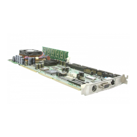
C h a p t e r 1 Introduction General Description The SBC8168 CPU card is an industrial grade CPU card incorporating the Intel 815E chipset and the Intel 815GMCH with built-in AGP2x VGA controller, both ensuring its compatibility with PCI bus passive backplanes. Its 6-layer structure reduces signal noise and built-in power management feature. -
Page 10: Specifications
SBC8168 Socket 370 All-in-One CPU Card Series User’s Manual Specifications Chipset: Intel 815E chipset CPU Socket: Socket 370 Bus Clock: 66/100/133 MHz CPU: Intel Socket 370 Celeron/Pentium III up to 933MHz L2 Cache: Integrated in CPU BIOS: Award 4Mbit PnP Flash BIOS... -
Page 11: Utilities Supported
SBC8168 Socket 370 All-in-One CPU Card Series User’s Manual Ethernet 2: (optional) Intel 82559 PCI Bus 10/100M Base-T Onboard Wake On LAN (via ATX power supply) Onboard RJ-45 connector USB Interface: 4 USB ports; USB Spec. Rev. 1.1 compliant IrDA: 1 IrDA pin-header for wireless communication... - Page 12 SBC8168 Socket 370 All-in-One CPU Card Series User’s Manual CRT Drivers Introduction...
-
Page 13: Board Dimensions
SBC8168 Socket 370 All-in-One CPU Card Series User’s Manual Board Dimensions 4.00 Introduction... -
Page 15: Jumpers And Connectors
SBC8168 Socket 370 All-in-One CPU Card Series User’s Manual C h a p t e r 2 Jumpers and Connectors Jumpers and Connectors... -
Page 16: Board Layout
SBC8168 Socket 370 All-in-One CPU Card Series User’s Manual Board Layout Jumpers and Connectors... -
Page 17: Jumper Settings
SBC8168 Socket 370 All-in-One CPU Card Series User’s Manual Jumper Settings Making the proper jumper settings configures the SBC8168 to match the needs of your application. The following summary table lists all onboard jumpers and their corresponding functions and/or default settings. -
Page 18: Diskonchip Memory Segment: Jp5
Watchdog Trigger Mode Setting: JP10 The watchdog timer is an indispensable feature of the SBC8168. It has a sensitive error detection function and a report function. When the CPU processing comes to a halt, the watchdog either generates a NMI or resets the CPU. -
Page 19: Connectors
SBC8168 Socket 370 All-in-One CPU Card Series User’s Manual Connectors The connectors allow the CPU card to connect with other parts of the system. Some problems encountered by your system may be a result from loose or improper connections. Ensure that all connectors are in place and firmly attached. -
Page 21: Chapter 3 Installation
C h a p t e r 3 Installation This chapter describes the hardware installation procedures on the SBC8168 all-in-one Socket 370 CPU card. The following is a list of typical peripherals required to build a minimum system: Power supply and passive backplane (optional) IBM™... -
Page 22: Ultra Dma 66/100 Drive Installation
SBC8168 Socket 370 All-in-One CPU Card Series User’s Manual Ultra DMA 66/100 Drive Installation To accommodate the fast transfer rate of Ultra DMA 66/100, an 80-conductor cable (with 40 pin connectors on both ends) is necessary when installing Ultra DMA/66 drives. The SBC8168, on this aspect, can support a total of 4 Ultra DMA/66 drives. -
Page 23: Completing Installation
2. Set the configuration jumpers according to the jumper settings on Chapter 2. 3. Install the SBC8168 CPU card into one of the slots on the passive backplane. You may allow the SBC8168 to stand alone as a single board computer. - Page 24 SBC8168 Socket 370 All-in-One CPU Card Series User’s Manual This page does not contain any information.
-
Page 25: Hardware Description
CPU to prevent any damage to the CPU. BIOS The system BIOS used in SBC8168 is Award Plug and Play BIOS. The SBC8168 contains a single 4Mbit Flash EPROM. For more detailed information, refer to Chapter 7 for a complete description of the BIOS setup utility and the available features accompanying it. -
Page 26: I/O Port Address Map
SBC8168 Socket 370 All-in-One CPU Card Series User’s Manual I/O Port Address Map The CPU card communicates via I/O ports. It has a total of 1KB port addresses that can be assigned to other devices via I/O expansion cards. Address... -
Page 27: Interrupt Controller
SBC8168 Socket 370 All-in-One CPU Card Series User’s Manual Interrupt Controller The SBC8168 is a fully PC compatible control board. It consists of 16 ISA interrupt request lines and 4 of the 16 can be either ISA or PCI. The mapping list of the 16 interrupt request lines is shown below;... -
Page 28: Flat Panel Bezel Connector
This 2-pin connector, designated at Pins 13 & 14 of CN11, connects the ATX power button of the front panel to the SBC8168 CPU card - allowing user to control the power on/off state of the ATX power supply. This jumper is only useful when installing an ATX power supply and CN15 cable to the system. -
Page 29: Enhanced Ide Interface Connector
64-byte buffer, and master data transaction. This feature, connected via connector CN1 and CN4, allows the SBC8168 to handle 4 IDE drives. Refer to Appendix B for the pinout assignments of CN1 and CN4. Hardware Description... -
Page 30: Vga Interface
SBC8168 Socket 370 All-in-One CPU Card Series User’s Manual VGA Interface 4.7.1 CRT Interface Controller The built-in Intel 815 GMCH is a high-performance super VGA display controller with onboard 4M bytes VGA RAM (optional). It is capable of driving a wide array of CRT displays. It can also support CRT at a maximum resolution of up to 1600x1200 with 8-bit colors. -
Page 31: Ethernet Connector
Ethernet Connector The RJ-45 connector is used for Ethernet. To connect the SBC8168 to 10-Base-T or 100-Base-T hub, just plug one end of the cable into the CN23 and connect the other end (phone jack) of the cable to a 10-Base-T hub. -
Page 32: Serial Port Interface
(CN8) supports RS-232 and COM2 (CN9) provide RS- 232/422/485 connectivity. 4.11.1 Serial Ports IRQ Selection SBC8168 uses a 10-pin connector for COM2 (CN9) and COM1 (CN8) with onboard Ethernet CPU card. Interrupt Requests on COM1 and COM2 are selected via IRQ4 and IRQ3 respectively. -
Page 33: Usb Connector
SBC8168 Socket 370 All-in-One CPU Card Series User’s Manual 4.13 USB Connector The Universal Serial Bus (USB) connector on the SBC8168 is for installation of peripherals supporting the USB interface. CN5 and CN6 are 10-pin USB pin-headers on the SBC8168. - Page 34 The specification enables new power management technology to evolve independently in operating systems and hardware while ensuring that they continue to work together. CN15 on the SBC8168 is a 6-pin header connector that provides ACPI interface. CN15 Hardware Description...
-
Page 35: Display Drivers
SBC8168 Socket 370 All-in-One CPU Card Series User’s Manual C h a p t e r 5 Display Drivers Introduction The Intel 815 GMCH includes a highly integrated graphics accelerator. Its architecture consists of dedicated multi-media engines executing in paralle to deliver high performance 3D, 2D, and motion compensation video capabilities. -
Page 36: Drivers Supported (Ethernet 1 And Ethernet 2)
SBC8168 Socket 370 All-in-One CPU Card Series User’s Manual Drivers Supported The Intel 815 GMCH is fully compatible with the VGA graphics standard at the register, gate, and BIOS levels. The manufacturer supplies fully VGA-compatible BIOS, end-user utilities and drivers for common application programs (e.g., Microsoft Windows). - Page 37 C h a p t e r 6 Ethernet Introduction The SBC8168 is equipped with two high performance Plug and Play Ethernet interfaces which are fully compliant with the IEEE 802.3 standard, and consisting of a RJ-45 connector (CN12 and CN23).
- Page 38 SBC8168 Socket 370 All-in-One CPU Card Series User’s Manual This page does not contain any information.
-
Page 39: Award Bios Utility
C h a p t e r 7 Award BIOS Utility Chapter 7 describes the different settings available in the Award BIOS that comes with the SBC8168 CPU card. Also contained here are instructions on how to set up the BIOS configuration. - Page 40 SBC8168 Socket 370 All-in-One CPU Card Series User’s Manual When you enter the Setup utility, the Main Menu screen will appear on the screen. The Main Menu allows you to select from various setup functions and exit choices. CMOS Setup Utility-Copyright © Award Software...
-
Page 41: Standard Cmos Features
SBC8168 Socket 370 All-in-One CPU Card Series User’s Manual Standard CMOS Features “Standard CMOS Setup” allows you to record some basic hardware configurations in your computer system and set the system clock and error handling. If the motherboard is already installed in a working system, you will not need to select this option. - Page 42 SBC8168 Socket 370 All-in-One CPU Card Series User’s Manual Date The date format is: the day of week, from Sun to Sat, determined by the BIOS, is read only Mont the month, Jan (1) through Dec (12) the date, from 1 to 31 (or the maximum allowed in the month), can key...
- Page 43 SBC8168 Socket 370 All-in-One CPU Card Series User’s Manual number of cylinders CYLS HEAD number of read/write heads write precompensation PRECOMP landing zone LANDZ number of sectors SECTOR SIZE Automatically adjust according to the configuration MODE Auto (for IDE HDD only): Normal (HD <...
- Page 44 SBC8168 Socket 370 All-in-One CPU Card Series User’s Manual Video This field selects the type of video display card installed in your system. You can choose the following video display cards: Enhanced Graphics Adapter/Video Graphics Array. For EGA, EGA/VG VGA, SEGA, SVGA or PGA monitor adapters. (default)
-
Page 45: Advanced Bios Features
SBC8168 Socket 370 All-in-One CPU Card Series User’s Manual Advanced BIOS Features This section allows you to configure and improve your system and allows you to set up some system features according to your preference. CMOS Setup Utility-Copyright © 1984-2000 Award Software... -
Page 46: Processor Number Feature
SBC8168 Socket 370 All-in-One CPU Card Series User’s Manual NOTE: Many disk diagnostic programs, which attempt to access the boot sector table, can cause the virus warning. If you will run such a program, disable the Virus Warning feature. CPU Internal Cache / External Cache Cache memory is additional memory that is much faster than conventional DRAM (system memory). -
Page 47: Boot Up Floppy Seek
SBC8168 Socket 370 All-in-One CPU Card Series User’s Manual Boot Up Floppy Seek When enabled, the BIOS seeks for number of track (40 or 80) of the installed floppy drive. 360K type has 40 tracks while 760K, 1.2M and 1.44M have 80 tracks. By default, this field is set to Enabled. -
Page 48: Advanced Chipset Features
SBC8168 Socket 370 All-in-One CPU Card Series User’s Manual C8000 - CBFFF Shadow/DC000 - DFFFF Shadow Shadowing ROM reduces available memory between 640KB and 1024KB. These fields determine whether optional ROM is copied to RAM or not. Advanced Chipset Features This Setup menu controls the configuration of the motherboard chipset. -
Page 49: System Bios Cacheable
SBC8168 Socket 370 All-in-One CPU Card Series User’s Manual SDRAM RAS-to-CAS Delay During DRAM refresh, both rows and columns are addressed separately. This field allows you to determine the timing of transition from Row Address Strobe (RAS) to Column Address Strobe (CAS). -
Page 50: System Memory Frequency
SBC8168 Socket 370 All-in-One CPU Card Series User’s Manual Display Cache Frequency This option specifies the clock speed of the onboard video RAM (in MHz). The settings are 100MHz or 133MHz. The default setting is 100MHz. System Memory Frequency This option specifies the clock speed of the unbuffered SDRAM modules installed onboard. -
Page 51: Integrated Peripherals
SBC8168 Socket 370 All-in-One CPU Card Series User’s Manual Integrated Peripherals This option sets your hard disk configuration, mode and port. CMOS Setup Utility-Copyright © 1984-2000 Award Software Integrated Peripherals Enabled On-Chip Primary PCI IDE Item Help On-Chip Secondary PCI IDE... -
Page 52: Usb Controller
SBC8168 Socket 370 All-in-One CPU Card Series User’s Manual IDE Primary/Secondary Master/Slave PIO The four IDE PIO (Programmed Input/Output) fields let you set a PIO mode (0-4) for each of the four IDE devices that the onboard IDE interface supports. Modes 0 through 4 provide successively increased performance. -
Page 53: Onboard Fdc Controller
SBC8168 Socket 370 All-in-One CPU Card Series User’s Manual Follows the conventional way of turning OFF system power BUTTON-ONLY (via power button). Upon selecting this option, the KB POWER ON Password line appears. Press <Enter> and you’ll be prompted to enter and confirm a password of your choice. -
Page 54: Parallel Port Mode
SBC8168 Socket 370 All-in-One CPU Card Series User’s Manual Parallel Port Mode Select an operating mode for the onboard parallel (printer) port. Select Normal unless your hardware and software require one of the other modes offered in this field. The options available are EPP1.9, ECP, SPP, ECPEPP1.7, EPP1.7. -
Page 55: Acpi Function
SBC8168 Socket 370 All-in-One CPU Card Series User’s Manual ACPI Function This item allows you to enable/disable the Advanced Configuration and Power Management (ACPI). The options available are Enabled, Disabled. ACPI Suspend Type This item allows you to select the type of ACPI suspend mode that your system will follow. -
Page 56: Video Off Method
SBC8168 Socket 370 All-in-One CPU Card Series User’s Manual Video Off Method This determines the manner in which the monitor is blanked. V/H SYNC + This causes the system to turn off the vertical and horizontal Blank synchronization ports and write blanks to the video buffer. -
Page 57: Resume By Alarm
SBC8168 Socket 370 All-in-One CPU Card Series User’s Manual Resume by Alarm When Enabled, your can set the date and time at which the RTC (real-time clock) alarm awakens the system from Suspend mode. 7.7.1 Reload Global Timer Events When Enabled, an event occurring on each device listed below restarts the global time for Standby mode. - Page 58 SBC8168 Socket 370 All-in-One CPU Card Series User’s Manual Reset Configuration Data Normally, you leave this field Disabled. Select Enabled to reset Extended System Configuration Data (ESCD) when you exit Setup or if you have installed a new add-on and the system reconfiguration has caused such a serious conflict that the operating system can not boot.
- Page 59 SBC8168 Socket 370 All-in-One CPU Card Series User’s Manual PCI/VGA can work with a MPEG ISA/VESA VGA card. When disabled, a PCI/VGA cannot work with a MPEG ISA/VESA Card. Award BIOS Utility...
-
Page 60: Pc Health Status
SBC8168 Socket 370 All-in-One CPU Card Series User’s Manual PC Health Status This option configures the PCI bus system. All PCI bus systems on the system use INT#, thus all installed PCI cards must be set to this value. CMOS Setup Utility-Copyright © 1984-2000 Award Software PC Health Status 1.600 V... -
Page 61: Frequency/Voltage Control
SBC8168 Socket 370 All-in-One CPU Card Series User’s Manual 7.10 Frequency/Voltage Control This option configures the PCI bus system. All PCI bus systems on the system use INT#, thus all installed PCI cards must be set to this value. CMOS Setup Utility-Copyright © 1984-2000 Award Software... -
Page 62: Load Fail Safe Defaults
SBC8168 Socket 370 All-in-One CPU Card Series User’s Manual 7.11 Load Fail Safe Defaults This option allows you to load the troubleshooting default values permanently stored in the BIOS ROM. These default settings are non-optimal and disable all high-performance features. -
Page 63: Load Optimized Defaults
SBC8168 Socket 370 All-in-One CPU Card Series User’s Manual 7.12 Load Optimized Defaults This option allows you to load the default values to your system configuration. These default settings are optimal and enable all high performance features. CMOS Setup Utility-Copyright © Award Software... -
Page 64: Set Supervisor / User Password
SBC8168 Socket 370 All-in-One CPU Card Series User’s Manual 7.13 Set Supervisor / User Password These two options set the system password. Supervisor Password sets a password that will be used to protect the system and Setup utility. User Password sets a password that will be used exclusively on the system. -
Page 65: Save & Exit Setup
SBC8168 Socket 370 All-in-One CPU Card Series User’s Manual 7.14 Save & Exit Setup This allows you to determine whether or not to accept the modifications. Typing “Y” quits the setup utility and saves all changes into the CMOS memory. Typing “N” brigs you back to Setup utility. -
Page 66: Exit Without Saving
SBC8168 Socket 370 All-in-One CPU Card Series User’s Manual 7.15 Exit Without Saving Select this option to exit the Setup utility without saving the changes you have made in this session. Typing “Y” will quit the Setup utility without saving the modifications. Typing “N”... - Page 68 SBC8168 Socket 370 All-in-One CPU Card Series User’s Manual This page does not contain any information.
-
Page 69: Appendix A Watchdog Timer
The SBC8168 CPU card uses version 2.0 of the watchdog timer. This onboard WDT generates either a system reset or non-maskable interrupt (NMI), depending on the settings made on jumper JP10 of SBC8168. Follow the steps below to enable and program the watchdog function of SBC8168. Start ↓... - Page 70 SBC8168 Socket 370 All-in-One CPU Card Series User’s Manual 0.5 sec. 5 secs. 50 secs. 100 secs. 1 sec. 10 secs. 100 secs. 200 secs. 1.5 secs. 15 secs. 150 secs. 300 secs. 2 secs. 20 secs. 200 secs. 400 secs.
-
Page 71: 40-Pin Ide Interface Connector: Cn1, Cn4
SBC8168 Socket 370 All-in-One CPU Card Series User’s Manual A p p e n d i x B Connector Pin Assignments 40-pin IDE Interface Connector: CN1, CN4 Description Description Description Reset # Data 7 Data 8 Data 6 Data 9... -
Page 72: Parallel Port Connector: Cn3
SBC8168 Socket 370 All-in-One CPU Card Series User’s Manual Parallel Port Connector: CN3 Description Description Strobe# Auto Form Feed# Data 0 Error# Data 1 Initialize# Data 2 Printer Select In# Data 3 Data 4 Data 5 Data 6 Data 7...
Need help?
Do you have a question about the SBC8168 and is the answer not in the manual?
Questions and answers