Table of Contents
Advertisement
Quick Links
Advertisement
Table of Contents
Troubleshooting

Related Manuals for Matrix E7XE-01


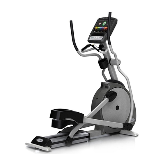
Summary of Contents for Matrix E7XE-01
- Page 1 E 7 x E - 0 1 E l l i p t i c a l t r a i n E r S E r V i c E M a n U a l...
-
Page 3: Table Of Contents
tablE of contEntS cHaptEr 1: SErial nUMbEr location ............1 cHaptEr 2: iMportant SafEty inStrUctionS Read and Save These Instructions ................3 Electrical Requirements ..................... 4 cHaptEr 3: prEVEntatiVE MaintEnancE Recommended Cleaning Tips ..................5 Check for Damaged Parts ..................5 Care and Maintenance Instructions ................ - Page 4 tablE of contEntS Troubleshooting - Touch Pad Issues ................32 Troubleshooting - Resistance Issues ................33 Troubleshooting - Pedals Slipping ................34 Troubleshooting - Noise Issues................... 34 8.10 Troubleshooting - Heart Rate Issues ................35 8.11 Troubleshooting - TV Issues ..................36 cHaptEr 9: part rEplacEMEnt gUidE Front Disk Replacement ....................
-
Page 5: Chapter 1: Serial Number Location
cHaptEr 1: SErial nUMbEr location 1.1 SErial nUMbEr location... - Page 6 cHaptEr 1: SErial nUMbEr location 1.1 SErial nUMbEr location - continUEd universal console serial number location...
-
Page 7: Chapter 2: Important Safety Instructions
This Elliptical Trainer is intended for commercial use. To ensure caUtion! If you experience chest pains, nausea, dizziness, or your safety and protect the equipment, read all instructions before shortness of breath, stop exercising immediately and consult operating the MATRIX Elliptical Trainer. your physician before continuing. When using an electrical product, basic precautions should always be caUtion! Any changes or modifications to this equipment followed including the following: could void the product warranty. -
Page 8: Electrical Requirements
Matrix power cords will void all warranties. groUnding inStrUctionS: The Matrix E7xe-01 Elliptical Trainer must be grounded. If it should malfunction or break down, grounding provides a path of least resistance for electric current to reduce the risk of electric shock. -
Page 9: Chapter 3: Preventative Maintenance
3.2 cHEck for daMagEd partS do not use any equipment that is damaged or has worn or broken Preventative maintenance and daily cleaning will prolong the life and parts. Use only replacement parts supplied by Matrix Fitness look of your MATRIX Elliptical Trainer. Systems. -
Page 10: Care And Maintenance Instructions
* Mild, water soluble, detergent – such as “Simple Green”, or other Matrix approved product montHlY maintenance items * Teflon based spray lubricant such as “Super Lube”, or other Matrix approved product 1) Inspect the console, handrails, link arms, pedal arms, and pedals * Vacuum cleaner with an extendable hose and crevasse tool for damage. -
Page 11: Touch Screen Care & Cleaning
cHaptEr 3: prEVEntatiVE MaintEnancE 3.4 toUcH ScrEEn carE & clEaning toUcH ScrEEn carE and clEaning * The touch screen requires very little maintenance. We recommend that you periodically clean the touch screen surface with a dry soft cloth. If necessary, we recommend the usage of Alcohol or Isopropyl Alcohol for difficult stains or sanitary purposes. * It is very important to avoid using any other chemical on the touch screen. -
Page 12: Chapter 4: Console Overlay And Workout Description
The information explaining how to program for various workouts will give an explanation about the contents of each screen on the machine. E7xE-01 EntErtainMEnt zonE iPoD®: Will take the user directly to the iPod screen to allow for iPod control and play list selection. -
Page 13: Workout Setup Steps
Above Average the resistance of the machine. Well Above Average tarGet Heart rate - The Matrix Ascent Trainer comes constant Watts - Constant Watts is a unique program that with standard digital contact heart rate sensors and are POLAR allows you to vary your cadence or RPM and the Ascent Trainer's telemetry compatible. -
Page 14: Chapter 5: Manager Mode
cHaptEr 5: ManagEr ModE 5.1 ManagEr ModE oVErViEw The Manager's Custom Mode allows the club owner to customize the Elliptical Trainer for the club. 1) To enter Manager Mode, press ENTER, 1, 0, 0, 1, ENTER on the lower display. Manager Mode will appear on the display (Figure A). 2) Follow the prompts to change the desired setting. 3) Press the ENTER key once the desired setting is correct to save. -
Page 15: Manager Mode - About Tab
cHaptEr 5: ManagEr ModE 5.2 ManagEr ModE - aboUt tab fUnction & dEfaUltS dEScriptionS ModifiEd ManagEr ModE About Serial Number This option displays the serial number of the Cannot be modified. platform and console. See Service Mode to edit the serial numbers. Accumulated Distance Total distance on the unit since production. -
Page 16: Manager Mode - Time Tab
cHaptEr 5: ManagEr ModE 5.3 ManagEr ModE - tiME tab fUnction & dEfaUltS dEScriptionS ModifiEd ManagEr ModE Time Maximum Time This option allows the club to set the Maximum: 99 Minutes Default: 60 Minutes maximum workout duration limits during Minimum: 5 Minutes peak and non peak hours. -
Page 17: Manager Mode - Defaults Tab
cHaptEr 5: ManagEr ModE 5.4 ManagEr ModE - dEfaUltS tab fUnction & dEfaUltS dEScription ModifiEd ManagEr ModE Defaults Default Level This option controls the default Maximum: 1 Default: 1 program level. Minimum: 20 Default Age This option controls the default user's Maximum: 100 Default: 30 age used in the target HR calculations. -
Page 18: Manager Mode - Language Tab
cHaptEr 5: ManagEr ModE 5.5 ManagEr ModE - tV tab ManagEr ModE fUnction & dEfaUltS dEScriptionS ModifiEd Default Channel This option controls the default TV channel Channels 1-999 Default: 1 on start up. Default Volume This option controls the default TV volume Maximum: 17 Default: 1 on start up. -
Page 19: Manager Mode - Tv Tab
cHaptEr 5: ManagEr ModE 5.6 ManagEr ModE - langUagE tab ManagEr ModE fUnction & dEfaUltS dEScriptionS ModifiEd Language Select default language. This option allows the user to select a flag for a specific language. langUagE flag Unit langUagE flag Unit langUagE flag Unit... -
Page 20: Chapter 6: Engineering Mode
cHaptEr 6: EnginEEring ModE 6.1 EnginEEring ModE oVErViEw The Engineering Mode allows the club owner to keep track of the technical settings and error history for the Elliptical Trainer. 1) To enter Engineering Mode, press ENTER, 2, 0, 0, 1, ENTER on the lower display. Engineering Mode will appear on the display (Figure A). 2) Follow the prompts to change the desired setting. -
Page 21: Engineering Mode - Calibration Tab
cHaptEr 6: EnginEEring ModE 6.2 EnginEEring ModE - calibration tab EnginEEring ModE fUnction & dEfaUltS dEScriptionS ModifiEd Calibration RPM Low Limit Charge: This option controls the RPM low limit to iPod Range: 0 - 255 Default: 10 charge. RPM Low Limit Resistance This option control the RPM low limit to show Range: 0 - 255 Default: 10... -
Page 22: Engineering Mode - Errors Tab
cHaptEr 6: EnginEEring ModE 6.3 EnginEEring ModE - StatiSticS tab EnginEEring ModE fUnction & dEfaUltS dEScriptionS ModifiEd Statistics This option displays the workout information for the unit. -
Page 23: Engineering Mode - Statistics Tab
cHaptEr 6: EnginEEring ModE 6.4 EnginEEring ModE - ErrorS tab EnginEEring ModE fUnction & dEfaUltS dEScriptionS ModifiEd Errors This option displays the error code history for the unit. -
Page 24: Engineering Mode - Clubs Tab
6: EnginEEring ModE 6.5 EnginEEring ModE - clUbS tab EnginEEring ModE fUnction & dEfaUltS dEScriptionS ModifiEd Clubs This option allows the club to select a screen Default: MATRIX header from a list. -
Page 25: Engineering Mode - Club Id Tab
cHaptEr 6: EnginEEring ModE 6.6 EnginEEring ModE - clUb id tab EnginEEring ModE fUnction & dEfaUltS dEScriptionS ModifiEd Club ID This option records the Club ID of the fitness facility. -
Page 26: Chapter 7: Service Mode
cHaptEr 7: SErVicE ModE 7.1 SErVicE ModE oVErViEw The Service Mode allows an authorized service provider to test and store information on the Elliptical Trainer. 1) To enter Service Mode, press ENTER, 3, 0, 0, 1, ENTER on the lower display. Service Mode will appear on the display (Figure A). 2) Follow the prompts to change the desired setting. -
Page 27: Service Mode - Setup Tab
cHaptEr 7: SErVicE ModE 7.2 SErVicE ModE - SEtUp tab SErVicE ModE fUnction & dEfaUltS dEScriptionS Setup Machine Type This option selects the current model. Default: Elliptical Trainer Serial Number This option displays the serial number of the console and frame. Accumulated Distance This option displays the accumulated workout distance since production. -
Page 28: Service Mode - Test Tab
cHaptEr 7: SErVicE ModE 7.3 SErVicE ModE - tESt tab SErVicE ModE fUnction & dEfaUltS dEScriptionS Test Keypad This option is for a keypad test. Touch Calibration This option starts a touch calibration. Follow the cross mark moving across the screen and touch. After testing 5 positions, touch the center to exit the test. -
Page 29: Service Mode - Date / Time Tab
cHaptEr 7: SErVicE ModE 7.4 SErVicE ModE - log tab SErVicE ModE fUnction & dEfaUltS dEScriptionS This option records key components replacement history. -
Page 30: Service Mode - Log Tab
cHaptEr 7: SErVicE ModE 7.5 SErVicE ModE - datE & tiME tab SErVicE ModE fUnction & dEfaUltS dEScriptionS Date & Time This option sets the current date and time on the machine. -
Page 31: Chapter 8: Troubleshooting
cHaptEr 8: troUblESHooting 8.1 ElEctrical diagraM... -
Page 32: Error Codes On The Console
cHaptEr 8: troUblESHooting 8.2 Error codES on tHE conSolE codE claSS dEScription SolUtion 0x02AB Machine type error. Set the correct machine type in Engineering Mode. 0x02B3 Resistance type error. Set the correct machine type in Engineering Mode. 0x0201 Low voltage on the battery Charge by running or by plugging (voltage under 11.2V). -
Page 33: Lcb Led Indicators
cHaptEr 8: troUblESHooting 8.3 lcb lEd indicatorS lEd indicator dEScription LED 1 RPM (AC Plug In). LED 2 LED 3 +15V LED 4 Bus Voltage LED 5 RPM (Generator). LED 6 Status 1 (Program operation). LED 7 Status 2 (Resistance value in middle 1/2 VCC). LED 8 Status 3 (Digital Communication). -
Page 34: Troubleshooting - Display Issues
cHaptEr 8: troUblESHooting 8.4 troUblESHooting - diSplay iSSUES no diSplay on tHE conSolE or tHE diSplay iS diM wHEn rUnning lEd 9 lEd 1 lEd 8 lEd 5 SyMptoM: The console will not power up or the display is dim. cHEck point poSSiblE iSSUE SolUtion... -
Page 35: Troubleshooting - Error 0X04A0
cHaptEr 8: troUblESHooting 8.5 troUblESHooting - Error 0x04a0 Error 0x04a0 (digital coMMUnication failUrE) lEd 1 lEd 8 SyMptoM: Error code 0x04A0 is displayed on the console. cHEck point poSSiblE iSSUE SolUtion LEDs 2, 3, 4, 6, and 7 should be ON. If they are OFF, the LCB is damaged. -
Page 36: Troubleshooting - Touch Pad Issues
cHaptEr 8: troUblESHooting 8.6 troUblESHooting - toUcH pad iSSUES all or SoME of tHE fUnction kEyS do not rESpond poSSiblE caUSES: 1) The touch pad is not calibrated properly. 2) The UCB is damaged. SolUtion: 1) Perform a touch pad calibration in Service Mode: a. -
Page 37: Troubleshooting - Resistance Issues
cHaptEr 8: troUblESHooting 8.7 troUblESHooting - rESiStancE iSSUES HigH or no rESiStancE poSSiblE caUSES: 1) The console cable is damaged or not properly plugged in. 2) The UCB is damaged. 3) The Generator is damaged. 4) The LCB is damaged. SolUtion: 1) Check the console cable connections at the UCB and LCB. -
Page 38: Troubleshooting - Pedals Slipping
cHaptEr 8: troUblESHooting 8.8 troUblESHooting - pEdalS Slipping pEdalS Slipping poSSiblE caUSES: 1) The belt tension is not enough. 2) The one way bearing is damaged. SolUtion: 1) Remove the covers and check the belt tension. a. The drive belt should be tightened to 170 ft / lbs. b. -
Page 39: Troubleshooting - Heart Rate Issues
cHaptEr 8: troUblESHooting 8.10 troUblESHooting - HEart ratE iSSUES HEart ratE fUnction doES not work or iS rEading incorrEctly poSSiblE caUSES: 1) The chest strap being used is not making good contact with the user's chest. 2) The chest strap is at a low battery status. 3) The chest strap is damaged. 4) The HR grips are damaged. 5) The HR board is damaged. -
Page 40: Troubleshooting - Tv Issues
8.11 troUblESHooting - tV iSSUES 1) This section will help with diagnosing problems with the integrated screen TV for the Matrix E7xe-01 Elliptical Trainer. 2) The TV should have power whenever the unit is powered up. If the TV will not power up when the power button is pressed: a) Press ENTER, 3, 0, 0, 1, ENTER on the lower number keypad. -
Page 41: Chapter 9: Part Replacement Guide
cHaptEr 9: part rEplacEMEnt gUidE 9.1 front diSk rEplacEMEnt 1) Remove the crank arm plastic cap at the front disk (Figure A). 2) Detach the crank from the crank arm (Figures B & C). 3) Locate the center cap in the center of the front disk (Figure D). figUrE a figUrE b figUrE d... - Page 42 E 7) Thread the Matrix disk removal tool into the center hub (Figure G). 8) Turn the center bolt of the removal tool clockwise until the main disk can be removed (Figures H and I). Repeat if necessary for the opposite side disk.
-
Page 43: Front Shroud Replacement
cHaptEr 9: part rEplacEMEnt gUidE 9.2 front SHroUd rEplacEMEnt 1) Remove the front disks as outlined in Section 8.1. 2) Remove the screws that hold the front shrouds in place and to each other on each side (Figure A). note: You will need to lift the console mast boot to remove some of the screws. -
Page 44: Lower Control Board (Lcb) Replacement
cHaptEr 9: part rEplacEMEnt gUidE 9.3 lowEr control board rEplacEMEnt 1) Turn off the power and disconnect the cord from the machine. 2) Remove the right side front disk from the machine as outlined in Section 8.1. 3) Remove the right side front shroud as outlined in Section 8.2. 4) Disconnect all wires from the LCB (Figure A). -
Page 45: Ecb (Electromagnetic Brake) Replacement
cHaptEr 9: part rEplacEMEnt gUidE 9.4 Ecb (ElEctronic brakE) rEplacEMEnt 1) Turn off power and disconnect the cord from the machine. 2) Remove the front disks as outlined in Section 8.1. 3) Remove the front shrouds as outlined in Section 8.2. 4) Unplug the ECB wire harness from the lower control board (Figure A). -
Page 46: Belts Removal And Installation - Short Belt Run
cHaptEr 9: part rEplacEMEnt gUidE 9.5 Ecb bElt rEplacEMEnt 1) Turn off the power and disconnect the cord from the machine. 2) Remove the left side front disk from the machine as outlined in Section 8.1. 3) Remove the left side shroud from the machine as oultined in Section 8.2. 4) Remove the screw holding the ECB axle in place on the right side of the frame (Figure A). -
Page 47: Belts Removal And Installation - Long Belt Run
cHaptEr 9: part rEplacEMEnt gUidE 9.6 driVE bElt rEplacEMEnt 1) Turn off the power and disconnect the cord from the machine. 2) Remove the right side front disk from the machine as outlined in Section 8.1. 3) Loosen the belt tension screw on the left side of the tension pulley and rotate the pulley counter clockwise until there is enough slack in the belt to remove it (Figures A &... -
Page 48: Pulley Axle Set Replacement
5) Remove the drive belt as outlined in Section 9.6. 6) Remove the 75 mm nut holding the pulley axle in place using the large socket available from Matrix (Figure A). 7) Use a hammer or mallet to remove the pulley axle from the left side (Figure B) and clean any debris from the frame (Figure C). -
Page 49: Drive Axle Set Replacement
6) Release any bent tabs on the lock washer around the 75 mm nut holding the drive axle set to the frame (Figure A). 7) Remove the 75 mm nut holding the drive axle set to the frame using the large socket available from Matrix (Figure B). -
Page 50: Console Replacement
cHaptEr 9: part rEplacEMEnt gUidE 9.9 conSolE rEplacEMEnt 1) Remove the 4 screws that hold the console to the top of the console mast (Figure A). figUrE a 2) Disconnect the data cable, heart rate, and ground wires and remove the console (Figure B). figUrE b 3) Reconnect the wire connections to the new console. -
Page 51: Overlay & Keypad Replacement
cHaptEr 9: part rEplacEMEnt gUidE 9.10 conSolE oVErlayS & kEypadS rEplacEMEnt 1) Remove the console as outlined in Section 8.9. 2) Remove the back cover of the console (Figure A). 3) Unplug and remove the faulty overlay (Figure B). figUrE a figUrE b 4) Clean the console area with alcohol to remove any left over adhesive (Figure C). - Page 52 cHaptEr 9: part rEplacEMEnt gUidE 9.10 conSolE kEypad / oVErlay rEplacEMEnt - continUEd 6) Peel part of the protective film from the back of the overlay (Figure E). 7) Push the overlay ribbon cable through the hole in the console and plug it in (Figure F). figUrE E figUrE f 8) Match the overlay to the cutout on the console (Figure G).
- Page 53 cHaptEr 9: part rEplacEMEnt gUidE 9.10 conSolE kEypad & oVErlay rEplacEMEnt - continUEd 9) Press down on the corners of the overlay to keep it in place, then remove the protective film (Figure H & I). figUrE H figUrE i 10) Once the overlay is in the correct position, press down on the overlay with a cloth to adhere it to the console plastic (Figure J).
-
Page 54: Handlebar Assembly Replacement
cHaptEr 9: part rEplacEMEnt gUidE 9.11 HandlEbar aSSEMbly rEplacEMEnt 1) Remove the two screws holding the plastic handlebar cover in place and remove the cover (Figures A & B). figUrE a figUrE b 2) Remove the 4 bolts that hold the handlebar to the console mast being careful to support the handlebar (Figures C and D). figUrE d figUrE c 3) Carefully remove the wires from inside the console mast until the connectors on the ends come free and disconnect. -
Page 55: Heart Rate Grips Replacement
cHaptEr 9: part rEplacEMEnt gUidE 9.12 HEart ratE gripS rEplacEMEnt 1) Using a flat screwdriver, pry the silver metal heart rate plate on the back side of the HR grip away from the plastic of the HR grip (Figure A). 2) Disconnect the HR grip wire and remove the metal plate (Figure B). -
Page 56: Cup Holder Replacement
cHaptEr 9: part rEplacEMEnt gUidE 9.13 cUp HoldEr rEplacEMEnt 1) Remove the 2 screws holding the cup holder onto the console mast (Figure A). figUrE a 2) Remove the cup holder (Figure B). figUrE b 3) Reverse Steps 1-2 to install a new cup holder. -
Page 57: Dual Action Handlebar Replacement
cHaptEr 9: part rEplacEMEnt gUidE 9.14 dUal action HandlEbar rEplacEMEnt 1) Remove the plastic cover where the dual action handlebar meets the pedal arm (Figure A). 2) Remove the bolt and bushings where the dual action handlebar and the pedal arm meet (Figure B). figUrE a figUrE b 3) Remove the two bolts holding the dual action handlebar to the console mast pivot (Figure C). -
Page 58: Console Mast Replacement
cHaptEr 9: part rEplacEMEnt gUidE 9.15 conSolE MaSt rEplacEMEnt 1) Remove the console as oultined in Section 8.9. 2) Remove the 2 screws on each side holding the dual action handlebars to the console mast pivot (Figures A & B). figUrE a figUrE b 3) Lift up the rubber boot at the bottom of the console mast (Figure C). -
Page 59: Foot Pedals Replacement
cHaptEr 9: part rEplacEMEnt gUidE 9.16 foot pEdalS rEplacEMEnt 1) Pull up on the rubber pad on top of the plastic pedal to expose the pedal screws (Figure A). 2) Remove the 4 Phillips screws that hold the plastic foot pedal to the foot plate (Figure B). figUrE a figUrE b 3) Remove the plastic foot pedal (Figure C). -
Page 60: Pedal Arm Replacement
cHaptEr 9: part rEplacEMEnt gUidE 9.17 pEdal arM rEplacEMEnt 1) Remove the plastic cover where the dual action handlebar meets the pedal arm (Figure A). 2) Remove the bolt and bushings where the dual action handlebar and the pedal arm meet (Figure B). note: Be sure to move the bushings from the old pedal arm to the new one (Figure C). - Page 61 cHaptEr 9: part rEplacEMEnt gUidE 9.17 pEdal arM rEplacEMEnt - continUEd 3) Remove the pedal as outlined in Section 8.16. 4) Remove the 3 bolts that hold on the mounting plate at the crank arm / pedal arm joint (Figure D). Note the plastic washer that mounts at the end of the shaft (Figure E). figUrE d figUrE E 5) Slide the pedal arm shaft out of the crank arm housing (Figure F) noting the order of the washers on the pedal arm shaft (Figure G). figUrE f figUrE g 6) Reverse Steps 1-5 to install a new pedal arm.
-
Page 62: Crank Arm Replacement
cHaptEr 9: part rEplacEMEnt gUidE 9.18 crank arM rEplacEMEnt 1) Remove the crank arm plastic cap at the front disk (Figure A). 2) Disconnect the crank arm from the crank assembly (Figure B). figUrE a figUrE b 3) Remove the 3 bolts that hold on the mounting plate at the crank arm / pedal arm joint (Figure C). Note the plastic washer that mounts at the end of the shaft (Figure D). figUrE c figUrE d... - Page 63 cHaptEr 9: part rEplacEMEnt gUidE 9.18 crank arM rEplacEMEnt - continUEd 4) Slide the pedal arm shaft out of the crank arm housing (Figure E) noting the order of the washers on the pedal arm shaft (Figure F). figUrE E figUrE f 5) Remove the 2 screws on each side holding on the rear end cap and remove it (Figure G &...
- Page 64 cHaptEr 9: part rEplacEMEnt gUidE 9.18 crank arM rEplacEMEnt - continUEd 6) Remove the middle plastic cover from between the pedals by pulling it towards the rear of the unit (Figure I). figUrE i 7) Remove the 3 screws holding the top roller track in place (Figure J). figUrE j 8) Once the top track is removed, the crank arm can be removed from the unit.
-
Page 65: Roller Replacement
cHaptEr 9: part rEplacEMEnt gUidE 9.19 rollEr rEplacEMEnt 1) Remove the 3 bolts that hold on the mounting plate at the crank arm / pedal arm joint (Figure A). Note the plastic washer that mounts at the end of the shaft (Figure B). figUrE a figUrE b 2) Slide the pedal arm shaft out of the crank arm housing (Figure C) noting the order of the washers on the pedal arm shaft (Figure D). figUrE c figUrE d... - Page 66 cHaptEr 9: part rEplacEMEnt gUidE 9.19 rollEr rEplacEMEnt - continUEd 3) Remove the 2 screws on each side holding on the rear end cap and remove it (Figure E & F). figUrE E figUrE f 4) Remove the middle plastic cover from between the pedals by pulling it towards the rear of the unit (Figure G). figUrE g...
- Page 67 5) Remove the 3 screws holding the top roller track in place (Figure H). 6) Remove the screw holding the roller to the crank arm (Figure I). figUrE H 7) Remove the roller from the crank arm using the roller puller available from Matrix (Figure J). figUrE i figUrE j 8) Reverse Steps 1-7 to install a new roller.
-
Page 68: Roller Track Replacement
cHaptEr 9: part rEplacEMEnt gUidE 9.20 rollEr track rEplacEMEnt 1) Remove the 3 bolts that hold on the mounting plate at the crank arm / pedal arm joint (Figure A). Note the plastic washer that mounts at the end of the shaft (Figure B). figUrE a figUrE b 2) Slide the pedal arm shaft out of the crank arm housing (Figure C) noting the order of the washers on the pedal arm shaft (Figure D). figUrE c figUrE d... - Page 69 cHaptEr 9: part rEplacEMEnt gUidE 9.20 rollEr track rEplacEMEnt - continUEd 3) Remove the 2 screws on each side holding on the rear end cap and remove it (Figure E & F). figUrE E figUrE f 4) Remove the middle plastic cover from between the pedals by pulling it towards the rear of the unit (Figure G). figUrE g...
- Page 70 cHaptEr 9: part rEplacEMEnt gUidE 9.20 rollEr track rEplacEMEnt - continUEd 5) Remove the 3 screws holding the top roller track in place (Figure H). figUrE H 6) Move the crank arm to the side off of the roller track. 7) Remove the 3 screws holding the bottom roller track to the frame (Figure I) and remove the roller track (Figure J).
-
Page 71: Testing The Elliptical Trainer
cHaptEr 9: part rEplacEMEnt gUidE 9.21 tESting tHE Elliptical trainEr oncE tHE Unit or rEplacEMEnt part iS fUlly inStallEd and aSSEMblEd and propErly placEd on tHE floor, USE tHE following inStrUctionS to tESt tHE MacHinE: 1) Without hitting start or entering any exercise modes, stand on the machine and hold the handlebars while initiating movement to simulate exercising. -
Page 72: Elliptical Trainer Specifications
cHaptEr 10: Elliptical trainEr SpEcificationS and aSSEMbly gUidE 10.1 Elliptical trainEr SpEcificationS conSolE Display Type 15: touch screen LCD Display Feedback Time, Distance, Calories, Calories per hour, Speed, Heart Rate, METs, Watts, RPM, Dynamic Profile Display, Static Profile Display Programs Manual, Rolling, Intervals, Fat Burn, Random, Fitness Test, Target HR, Constant Watts Resistance Levels... -
Page 73: Fasteners & Assembly Tools
cHaptEr 10: Elliptical trainEr SpEcificationS and aSSEMbly gUidE 10.2 faStEnErS & aSSEMbly toolS QUantity part # SkEtcH dEScription packagE color PHILLIPS SCREWDRIVER 13 MM OPEN WRENCH 4 MM ALLEN WRENCH 6 MM ALLEN WRENCH 8 MM ALLEN WRENCH SOCKET HEAD CAP SCREW (M8 X 20L) PINK WASHER (8.4 X 15.5 X 1.6T) PINK... -
Page 74: Elliptical Trainer Assembly Steps
cHaptEr 10: Elliptical trainEr SpEcificationS and aSSEMbly gUidE 10.3 Elliptical trainEr aSSEMbly StEpS... - Page 75 cHaptEr 10: Elliptical trainEr SpEcificationS and aSSEMbly gUidE 10.3 Elliptical trainEr aSSEMbly StEpS - continUEd...
- Page 76 cHaptEr 10: Elliptical trainEr SpEcificationS and aSSEMbly gUidE 10.3 Elliptical trainEr aSSEMbly StEpS - continUEd...
- Page 77 cHaptEr 10: Elliptical trainEr SpEcificationS and aSSEMbly gUidE 10.3 Elliptical trainEr aSSEMbly StEpS - continUEd...
- Page 78 cHaptEr 10: Elliptical trainEr SpEcificationS and aSSEMbly gUidE 10.3 Elliptical trainEr aSSEMbly StEpS - continUEd...
- Page 79 cHaptEr 10: Elliptical trainEr SpEcificationS and aSSEMbly gUidE 10.3 Elliptical trainEr aSSEMbly StEpS - continUEd...
- Page 80 cHaptEr 10: Elliptical trainEr SpEcificationS and aSSEMbly gUidE 10.3 Elliptical trainEr aSSEMbly StEpS - continUEd StEp 7...
- Page 81 cHaptEr 10: Elliptical trainEr SpEcificationS and aSSEMbly gUidE 10.3 Elliptical trainEr aSSEMbly StEpS - continUEd StEp 8...
- Page 82 cHaptEr 10: Elliptical trainEr SpEcificationS and aSSEMbly gUidE 10.3 Elliptical trainEr aSSEMbly StEpS - continUEd final aSSEMbly...
-
Page 83: Leveling The Elliptical Trainer
cHaptEr 10: Elliptical trainEr SpEcificationS and aSSEMbly gUidE 10.4 lEVEling tHE Elliptical trainEr stabiliZinG tHe elliPtical trainer After positioning the elliptical trainer in its intended location, check its stability by attempting to shake it side to side. Shaking or wobbling indicates that your elliptical trainer needs to be leveled. -
Page 84: Tv Programming Instructions
cHaptEr 10: Elliptical trainEr SpEcificationS and aSSEMbly gUidE 10.5 tV prograMMing inStrUctionS 1) Press ENTER, 1, 0, 0, 1, ENTER on the lower keypad and Manager Mode will appear on the display. 2) Press TV on the display (Figure A). 3) Press Setup on the display and a TV will appear in the top right corner (Figure B). - Page 85 cHaptEr 10: Elliptical trainEr SpEcificationS and aSSEMbly gUidE 10.5 tV prograMMing inStrUctionS - continUEd 7) Then go down to CHANNEL SCAN, use the volume button to select it (Figure E). 8) Move the cursor down to START TO SCAN and use the volume button to select it (Figure F). figUrE E figUrE f 9) If the channels are now coming in clearly, press the HOME key to return to normal operation (Figure G).
-
Page 86: Chapter 11: Software Upgrade Procedure
cHaptEr 11: SoftwarE UpgradE procEdUrE 11.1 SoftwarE UpgradE procEdUrE 1) Copy three software files (7xe deploy.cab, io.txt, and update.config) onto a USB drive. 2) Turn on the power to the elliptical trainer, and wait until the standby picture has been cleared (Figure A). 3) Insert the USB drive into the Reprogram Port in the back of the console back cover (Figure B). - Page 87 notES...
- Page 88 M atrix fitn ES S Sy S tEM S c o r p. 1610 LANDMARK DRIV E C OTTAGE GR O VE WI 535 27 U S A w w w. m a t r i x f i t n e s s . c o m TOLL FREE 866.693.4863 FA X 6 08.
Need help?
Do you have a question about the E7XE-01 and is the answer not in the manual?
Questions and answers