Table of Contents
Advertisement
Quick Links
Code : SEA 304
ASSEMBLY MANUAL
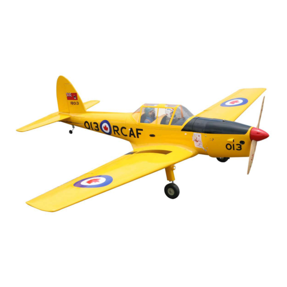
Speciications:
Wingspan--------------- 80.0 in (203.2 cm).
Wing area--------------- 937.8 sq.ins (60.5 sq.dm).
Weight------------------- 10.4 lbs (4.7 kg).
Length------------------- 57.2 in (145.2 cm).
Engine/Motor size----- 20cc gasoline.
Radio--------------------- 5 channels with 7 servos.
1
Advertisement
Table of Contents

Related Manuals for Seagull Models SEA 304


Summary of Contents for Seagull Models SEA 304
- Page 1 Code : SEA 304 ASSEMBLY MANUAL Speciications: Wingspan--------------- 80.0 in (203.2 cm). Wing area--------------- 937.8 sq.ins (60.5 sq.dm). Weight------------------- 10.4 lbs (4.7 kg). Length------------------- 57.2 in (145.2 cm). Engine/Motor size----- 20cc gasoline. Radio--------------------- 5 channels with 7 servos.
-
Page 2: Kit Contents
Instruction Manual. DHC-1 CHIPMUNK INTRODUCTION. hank you for choosing the DHC-1 CHIPMUNK ARTF by SG MODELS . he DHC-1 CHIP- MUNK was designed with the intermediate/advanced sport lyer in mind. It is a semi scale air- plane which is easy to ly and quick to assemble. he airframe is conventionally built using balsa, plywood to make it stronger than the average ARTF, yet the design allows the aeroplane to be kept light. -
Page 3: Additional Items Required
KIT CONTENTS. HINGING THE FLAP. SEA304 DHC-1 CHUPMUNK 1. Fuselage 2. Wing set (2) 3. Tail set (2) 4. Canopy 5. Cowling 6. Wing tube 7. Pilot 8. Wheel pants 9. landing gear 10. Fuel tank 11. Tail wheel ADDITIONAL ITEMS REQUIRED. �... -
Page 4: Hinging The Aileron
Instruction Manual. DHC-1 CHIPMUNK T-pin. Hinge. 3) Slide the wing panel on the aileron until there is only a slight gap. he hinge is now centered on the wing panel and aileron. Re- move the T-pins and snug the aileron against the wing panel. -
Page 5: Installing The Aileron Servos
Note : Work the aileron up and down sev- eral times to “work in” the hinges and check for proper movement. INSTALL THE AILERONS CONTROL HORN. Fiberglass control horn 5) Turn the wing panel over and delect the aileron in the opposite direction from the opposite side. - Page 6 Instruction Manual. DHC-1 CHIPMUNK 2) Use drill bit in a pin vise to drill the mouting holes in the blocks. 1.5mm 3) Apply 2-3 drops of thin C/A to each of the mounting holes. Allow the C/A to cure without using accelerator. C/A glue Minimum servo spec.
-
Page 7: Aileron Pushrod Installation
C/A glue 7) Remove the string from the wing at the 8) Set the aileron hatch in place and use a servo location and use the tape to attach it Phillips screw driver to install it with four to the servo extension lead. Pull the lead wood screws. -
Page 8: Installing Landing Gear
Instruction Manual. DHC-1 CHIPMUNK Repeat the procedure for the aileron pushrod. 40mm 40mm M3 lock nut. M3 clevis. M3 lock nut. M3 clevis. 80mm 80mm INSTALLING THE FLAP SERVO. Repeat the procedure for the lap servo. INSTALLING LANDING GEAR. 1)Locate items necessary to install Sprin INSTALLING THE FLAP PUSHROD. - Page 9 Use a 6 to 12 volt battery.
- Page 10 Instruction Manual. DHC-1 CHIPMUNK...
- Page 12 Instruction Manual. DHC-1 CHIPMUNK...
-
Page 13: Installing The Fuselage Servos
INSTALLING THE FUSELAGE SERVOS. Because the size of servos difer, you Trim and cut. may need to adjust the size of the precut opening in the mount. he notch in the sides of the mount allow the servo lead to pass through. -
Page 14: Installing The Stopper Assembly
Instruction Manual. DHC-1 CHIPMUNK Vent tube. Fuel pick up tube. INSTALLING THE STOPPER ASSEMBLY. 1) Using a modeling knife, carefully cut of the rear portion of one of the 3 nylon Fuel fill tube. tubes leaving 1/2” protruding from the rear of the stopper. -
Page 15: Engine Mount Installation
8) Use balsa block to hold in place the fuel tank with C/A glue to secure the fuel tank inside the fuselage ENGINE MOUNT INSTALLATION. 1) Locate the items necessary to install the engine mount included with your model. 2) Use four 4x30mm head bolts and four Ven tube. -
Page 16: Mounting The Engine
Instruction Manual. DHC-1 CHIPMUNK 3) Use a drill to drill the four holes in the engine mount rails. MOUNTING THE ENGINE. 1) Position the engine with the drive washer (145mm) forward of the iewall as shown. Machine screw M4x30mm 145mm 4) he irewall has the location for the throttle pushrod tube (pre-drill). - Page 17 Pushrod wire. 8) Reinstall the servo horn by sliding the connector over the pushrod wire. Cent- er the throttle stick and trim and install the servo horn perpendiular to the servo center line. 9) Move the throttle stick to the closed po- sition and move the carburetor to closed.
- Page 18 Instruction Manual. DHC-1 CHIPMUNK 1) Tape the cowl to the fuselage using COWLING. low-tack tape. 2) Use a drill and drill bit to drill the holes for the cowl mounting screws. Make sure the cowl position is correct before drill- ing each hole.
- Page 19 Because of the size of the cowl, it may be nec- essary to use a needle valve extension for the high speed needle valve. Make this out of suf- icient length 1.5mm wire and install it into the end of the needle valve. Secure the wire in place by tightening the set screw in the side of the needle valve.
- Page 20 Instruction Manual. DHC-1 CHIPMUNK - Motor: 110 - 2000 Watts - Propeller: 17x8 ~ 19x10 - ESC: 85A - 8S- 9S Lipo 3) Attach the electric motor box to the irewall centered with the cross lines drawn on the electric motor box and ire- wall.
- Page 21 M4x20mm 145mm 5) Attach the speed control to the side of the motor box using two-sided tape and tie wraps. Connect the appropriate leads from the speed control to the mo- tor. Make sure the leads will not interfere with the operation of the motor. Battery.
-
Page 22: Installing The Horizontal Stabilizer
Instruction Manual. DHC-1 CHIPMUNK INSTALLING THE HORIZONTAL STABILIZER. 1) Using a ruler and a pen, locate the cen- terline of the horizontal stabilizer, at the trailing edge, and place a mark. Use a tri- M6x60mm angle and extend this mark, from back to front, across the top of the stabilizer. -
Page 23: Installing The Elevators
7) When you are sure that everything is 4) With the stabilizer held irmly in place, aligned correctly, mix up a generous amount use a pen and draw lines onto the stabilizer of 30 Minute Epoxy. Apply a thin layer to the where it and the fuselage sides meet. - Page 24 Instruction Manual. DHC-1 CHIPMUNK INSTALL ELEVATOR CONTROL HORN. Fiberglass control horn 1) While holding the vertical stabilizer irmly in place, use a pen and draw a line on each side of the vertical stabilizer where it meets the top of the fuselage. FillE poxy.
-
Page 25: Mounting The Tail Wheel
3x15mm C/A glue.. 3) When you are sure that everything is aligned correctly, mix up a gener- ous amount of Flash 30 Minute Epoxy. Apply a thin layer to the mounting slot and to bottom of the vertical stabilizer mounting area. Apply epoxy to the bot- tom and top edges of the iller block and to the lower hinge also. -
Page 26: Hinging The Rudder
Instruction Manual. DHC-1 CHIPMUNK HINGING THE RUDDER. Glue the top two rudder hinges in place using the same techniques used to hinge the ailerons. Epoxy. INSTALL RUDDER CONTROL HORN. - Page 27 Elevator control horn. 3) hread one clevis and M2 lock nut on to each elevator control rod. hread the Epoxy. horns on until they are lush with the ends of the control rods. 4) Elevator and rudder pushrods assem- bly as pictures below. ELEVATOR PUSHROD HORN INSTALLATION.
- Page 28 Instruction Manual. DHC-1 CHIPMUNK Control horn. Metal clevis. M2 lock nut. Elevator pushrod. Wire keeper. INSTALLATION PILOT AND CANOPY. 1) Locate items necessary to install pilot and canopy. RUDDER PUSHROD HORN INSTALLATION. 2) A scale pilot is included with this ARF. he Pilot included itting well to the cock- pit.
- Page 29 If you are going to install a pilot igure, 4) Epoxy canopy onto the fuselage. Trace around the canopy and onto the fuselage please use a sanding bar to sand the base using a epoxy. of the igure so that it is lat. 3) Position the pilot igure on the canopy loor as show.
- Page 30 Instruction Manual. DHC-1 CHIPMUNK Wing tube. Insert two wing panels as pictures below. 4x20mm...
-
Page 31: Apply The Decals
1) It is critical that your airplane be balanced correctly. Improper balance will cause your plane to lose control and crash. THE CENTER OF GRAV- ITY IS LOCATED 130MM BACK FROM THE LEADING EDGE OF THE WING AT THE WING ROOT. 2) Mount the wing to the fuselage. -
Page 32: Control Throws
Instruction Manual. DHC-1 CHIPMUNK 130mm CONTROL THROWS. Ailerons: Rudder: High Rate : High Rate : Up : 20 mm Right : 30 mm Down : 20 mm Let : 30 mm Low Rate : Low Rate : Up : 15 mm Right : 20 mm Down : 15 mm Let : 20 mm... -
Page 33: Flight Preparation
FLIGHT PREPARATION. PREFLIGHT CHECK. Check the operation and direction of the 1) Completely charge your transmit- elevator, rudder, ailerons and throttle. ter and receiver batteries before your irst day of lying. A) Plug in your radio system per the 2) Check every bolt and every glue joint manufacturer’s instructions and turn eve- in the DHC-1 CHIPMUNK to ensure rything on. - Page 34 Instruction Manual. DHC-1 CHIPMUNK If you have any queries, or are interested in our products, please feel free to contact us Factory : 12/101A - Hamlet 4 - Le Van Khuong Street - Dong hanh Ward - Hoc Mon District - Ho Chi Minh City - Viet Nam. Oice : 62/8 Ngo Tat To Street - Ward 19 - Binh hanh District - Ho Chi Minh City - Viet Nam Phone : 848 - 86622289 or 848- 36018777...
Need help?
Do you have a question about the SEA 304 and is the answer not in the manual?
Questions and answers