Table of Contents
Advertisement
Quick Links
WWW.SEAGULLMODELS.COM
A S S E M B L Y M A N U A L
" Graphics and specifications may change without notice "
Code : SEA237
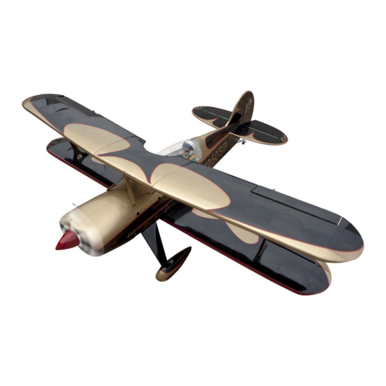
Specifications:
Wingspan---------------61 in ( 155 cm).
Wing area---------------1023 sq.in ( 66 sq.dm).
Weight-------------------9.3 lbs ( 4.2kg).
Length-------------------48.2 in (122.4cm).
Engine-------------------0.91 glow or gas
Motor--------------------1200-1700 watt electric
( Power 60)
Radio--------------------6 channels with 6 servos.
Electric conversion: Optional.
www.seagullmodels.com
1
Advertisement
Table of Contents

Related Manuals for Seagull Models STEEN SKYBOLT N250SB 15CC


Summary of Contents for Seagull Models STEEN SKYBOLT N250SB 15CC
- Page 1 WWW.SEAGULLMODELS.COM A S S E M B L Y M A N U A L “ Graphics and specifications may change without notice “ Code : SEA237 Specifications: Wingspan---------------61 in ( 155 cm). Wing area---------------1023 sq.in ( 66 sq.dm). Weight-------------------9.3 lbs ( 4.2kg). Length-------------------48.2 in (122.4cm).
-
Page 2: Kit Contents
Instruction Manual. INTRODUCTION. Thank you for choosing the STEEN SKYBOLT ARTF by SEAGULL MODELS COMPANY LTD,. The STEEN SKYBOLT was designed with the intermediate/advanced sport flyer in mind. It is a semi scale airplane which is easy to fly and quick to assemble. The airframe is conventionally built using balsa, plywood to make it stronger than the average ARTF, yet the design allows the aeroplane to be kept light. -
Page 3: Hinging The Aileron
WWW.SEAGULLMODELS.COM HINGING THE AILERON. KIT CONTENTS. Note : The control surfaces, including the ai- SEA23701 Fuselage lerons, elevators, and rudder, are prehinged SEA23702 Upper Wing set with hinges installed, but the hinges are not glued in place. It is imperative that you prop- SEA23703 Lower Wing set erly adhere the hinges in place per the steps SEA23704 Tail set... -
Page 4: Hinging The Elevators
STEEN SKYBOLT Instruction Manual. 4) Deflect the aileron and completely satu- 8) After both ailerons are securely hinged, rate each hinge with thin C/A glue. The ailer- firmly grasp the wing panel and aileron to ons front surface should lightly contact the make sure the hinges are securely glued and wing during this procedure. - Page 5 WWW.SEAGULLMODELS.COM INSTALL ELEVATOR CONTROL HORN. Fiberglass control horn. INSTALL THE AILERONS CONTROL HORN. Epoxy. Elevator fiberglass control horn. Fiberglass control horn Epoxy. Epoxy. INSTALL RUDDER CONTROL HORN. Repeat steps to install the rudder control horn as same as steps done for ailerons. Aileron control horn.
-
Page 6: Installing The Fuselage Servos
STEEN SKYBOLT Instruction Manual. THROTTLE SERVO ARM INSTALLATION. Install adjustable servo connector in the servo arm as same as picture below: Loctite secure. Adjustable servo Epoxy. connector. Servo arm. Throttle servo arm. Rudder fiberglass control horn. INSTALLING THE FUSELAGE SERVOS. Because the size of servos differ, you may need to adjust the size of the precut opening in the mount. - Page 7 WWW.SEAGULLMODELS.COM Switch. INSTALLING THE ENGINE SWITCH. Trim and cut. Switch. Vent tube. Fuel pick up tube. INSTALLING THE STOPPER ASSEMBLY. Fuel fill tube. 1) Using a modeling knife, carefully cut off the rear portion of one of the 3 nylon 3) Carefully bend the second nylon tube up tubes leaving 1/2”...
-
Page 8: Fuel Tank Installation
STEEN SKYBOLT Instruction Manual. 5) With the stopper assembly in place, the weighted pick-up should rest away from the rear of the tank and move freely inside the tank. The top of the vent tube should rest just below the top of the tank. It should not touch C/A glue. -
Page 9: Engine Mount Installation
WWW.SEAGULLMODELS.COM 2) Use a pin drill and 4mm drill bit to ENGINE MOUNT INSTALLATION. drill a small indentation in the mount for the engine mounting screw. 1) Locate the items necessary to install the engine mount included with your model. 4x30mm 2) Use four 4x30mm head bolts and four 4mm washers to attach the engine mount... - Page 10 STEEN SKYBOLT Instruction Manual. Machine screw M4x30mm 8) Reinstall the servo horn by sliding the connector over the pushrod wire. Center Pushrod wire. the throttle stick and trim and install the servo horn perpendicular to the servo center line. 9) Move the throttle stick to the closed po- sition and move the carburetor to closed.
- Page 11 WWW.SEAGULLMODELS.COM COWLING. Please see these below pictures. Because of the size of the cowl, it may be nec- essary to use a needle valve extension for the high speed needle valve. Make this out of suf- ficient length 1.5mm wire and install it into the end of the needle valve.
- Page 12 STEEN SKYBOLT Instruction Manual. M4x20mm Thread locker glue. INSTALLING THE MAIN LANDING GEAR TO FUSELAGE. M4x20mm WHEELS AND WHEEL PANTS. 1) Locate the items neccessary to install 2) Follow diagram below for wheel pant installation: 1) The blind nuts for securing the land- Use a drill and 8mm drill bit to drill a ing gear are already mounted inside the hole in the wheel pants.
- Page 13 WWW.SEAGULLMODELS.COM 4) Slide the collar to the axle and setscrew the collars to secure the collar to the axle and then slider the wheel on the axle with a drop of oil on the axle so the wheel will spin freely when installed. Prepare a second collar and tighten the setscrew using hex wrench to secure the collar to the axle.
- Page 14 STEEN SKYBOLT Instruction Manual. 4) Attach the motor to the front of the electric motor box using four 4mm blind nut, four M3x12mm hex head bolts to se- cure the motor. Please see picture shown. 2) Recommend the items necessary to in- stall the electric power conversion parts included with your model.
- Page 15 WWW.SEAGULLMODELS.COM 5) Attach the motor to the front of the electric motor box using four 4mm blind nut, four M3x12mm hex head bolts to se- cure the motor. Please see picture shown. Speed control M3x12mm Epoxy 130 mm Balsa stick. Epoxy 6) Attach the speed control to the side of the motor box using two-sided tape...
-
Page 16: Installing The Aileron Servos
STEEN SKYBOLT Instruction Manual. M3x10mm INSTALLING THE AILERON SERVOS. INSTALLING THE SPINNER. Servos Small weight Thread Because the size of servos differ, you may need to adjust the size of the precut opening in the mount. The notch in the sides of the mount allow the servo lead to The propeller should not touch any pass through. - Page 17 WWW.SEAGULLMODELS.COM 6) Secure the servo to the aileron hatch using Phillips screwdriver and the screws provided with the servo. 3) Use drill bit in a pin vise to drill the mouting holes in the blocks. 7) Apply 1-2 drops of thin C/A to each of the mounting tabs.
-
Page 18: Installing The Aileron Servo
STEEN SKYBOLT Instruction Manual. 9) Set the aileron hatch in place and use a Phillips screw driver to install it with four wood screws. 2x10mm INSTALLING THE AILERON SERVO. Repeat the procedure for the aileron servo. -
Page 19: Installing The Horizontal Stabilizer
WWW.SEAGULLMODELS.COM AILERON PU SHROD HORN INSTALLATION. Nylon Snap keeper. Please see below pictures. Hex Nut. Fuel tubing. INSTALLING THE HORIZONTAL STABILIZER. Use a felt tip pen to mark the wire where 1) Using a ruler and a pen, locate the cen- it crosses the hole. - Page 20 STEEN SKYBOLT Instruction Manual. 3) Place the stabilizer on the stabilizer When cutting through the covering mounting platform at the rear of the fu- to remove it, cut with only enough pressure selage. to only cut through the covering itself. Cut- ting into the balsa structure may weaken 6) Using a modeling knife, carefully re- move the covering that overlaps the sta-...
-
Page 21: Installing Vertical Stabilizer
WWW.SEAGULLMODELS.COM 2) While holding the vertical stabilizer firmly in place, use a pen and draw a line on each side of the vertical stabilizer where it meets the top of the fuselage. Epoxy INSTALLING VERTICAL STABILIZER 3) Slide the vertical stabilizer back in- place. - Page 22 STEEN SKYBOLT Instruction Manual. 4) When you are sure that everything 4) Thread one clevis and M2 lock nut on is aligned correctly, mix up a generous to each elevator control rod. Thread the amount of 30 Minute Epoxy. Apply a thin horns on until they are flush with the layer to the bottom of the vertical stabi- ends of the control rods.
- Page 23 WWW.SEAGULLMODELS.COM Repeat steps to install the remaining el- evator pushrod. RUDDER PUSHROD HORN INSTALLATION. 1) Locate items necessary to install rud- der pushrod. Elevator control horn. Rudder control horn. Cut. M2 clevis. M2 lock nut. Rudder pushrod.
-
Page 24: Tail Wheel Installation
STEEN SKYBOLT Instruction Manual. TAILWHEEL INSTALLATION. Locate items necessaryto install tail- wheel. 3x25mm. Aluminum tail landing gear. INSTALLATION PILOT AND CANOPY. 3x20mm. 1) Locate items necessary to install pilot, seats. 2) A scale pilot is included with this ARF. The Seagull Pilot included fitting well to the cockpit. -
Page 25: Apply The Decals
WWW.SEAGULLMODELS.COM 3) Position the pilot figure on the canopy APPLY THE DECALS. floor as shown. Use epoxy to glue the base of the pilot figure to the cockpit floor, 1) If all the decals are precut and ready to please see pictures as shown. stick. - Page 26 STEEN SKYBOLT Instruction Manual. 3) Place the cabane struts on position ,not- 5) Use a 2.5mm hex wrench to slowly ing their position as shown in the photo. tighten the hardware securing the cabane Loosely install the four M3x12 socket head struts in position on the fuselage.You machine screws and M3 washers.Leave , may want to use hemostats to hold the...
- Page 27 WWW.SEAGULLMODELS.COM Insert two wing panels as pictures below. Receiver. Battery. ATTACHMENT WING- FUSELAGE. Cut. Insert cover hatch on fuselage as pictures below. Epoxy. Attach the aluminium tube into fuselage. Wing tube.
- Page 28 STEEN SKYBOLT Instruction Manual. Epoxy. Wing bolt. 4x10mm INSTALLATION WING STRUTS. 1) Locate the items for this section of the manual.
- Page 29 WWW.SEAGULLMODELS.COM 2) Attach the wing strut to the top of the Once centered, slide the silicone tubing bottom wing panel using an M3x12 ma- over the forks of the clevis to prevent it chine screw. from opening accidentally. Apply thread- lock on the nuts and clevises to prevent them from vibrating loose.
-
Page 30: Control Throws
STEEN SKYBOLT Instruction Manual. *If possible, first attempt to balance the BALANCING. model by changing the position of the re- ceiver battery and receiver. If you are un- 1) It is critical that your airplane be able to obtain good balance by doing so, balanced correctly. - Page 31 WWW.SEAGULLMODELS.COM...
-
Page 32: Flight Preparation
If it does not, flip the servo reversing excessive vibration which could lead switch on your transmitter to change to engine and/or airframe failure. the direction. We wish you many safe and enjoyable flights with your STEEN SKYBOLT N250SB 15cc.
Need help?
Do you have a question about the STEEN SKYBOLT N250SB 15CC and is the answer not in the manual?
Questions and answers