
Related Manuals for FIC AZ31


Summary of Contents for FIC AZ31
- Page 1 AZ31 MAINBOARD MANUAL DOC No.: M00402 Rev. : A2 Date : 7, 2000 Part No. : 25-11523-22...
-
Page 2: Handling Precautions
Notice Handling Precautions Warning: 1. Static electricity may cause damage to the integrated circuits on the motherboard. Before handling any motherboard outside of its protective packaging, ensure that there is no static electric charge in your body. 2. There is a danger of explosion if the battery is incorrectly replaced. -
Page 3: Table Of Contents
The AZ31 Mainboard ..............1-3 Main Features ................1-4 ACPI Ready ................... 1-6 FIC Unique Innovation for UsersII (NOVUS II) - Enhanced Mainboard Features and System Support ....1-6 Chapter 2 Installation Procedures Quick Reference (from Page 2-2 to 2-4) .......... 2-2 Mainboard Layout .............. - Page 4 AZ31 Mainboard Manual Chapter 3 BIOS Setup CMOS Setup Utility ............... 3-1 Standard CMOS Setup ..............3-2 Hard Disk Configurations ............3-2 Advanced BIOS Features .............. 3-3 Advanced Chipset Features ............3-6 Integrated Peripherals ..............3-11 Power Management Setup ............. 3-15 PNP/PCI Configurations ..............
-
Page 5: Chapter 1 Overview
128KB of on-chip level one (L1) , while the Duron features full-speed, on-chip L2 cache memory, and enhanced 3DNow!™ technology. The 1stMainboard AZ31 has 3 DIMM, for up to 1.5 GB of SDRAM, utilizes the latest PC133 SDRAM technology and is equipped with ECC memory support. -
Page 6: Package Checklist
AZ31 Mainboard Manual Package Checklist If you discover any item below was damaged or lost, please contact your vendor. The mainboard This user manual One FDD cable One HDD cable One ATA/66 cable Audio Alert II module (optional) Two software CDs... -
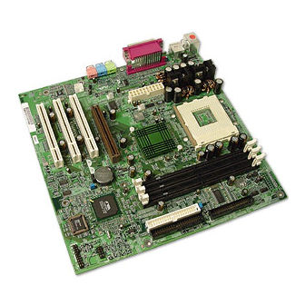
Page 7: The Az31 Mainboard
Overview The AZ31 Mainboard 1 - 3... -
Page 8: Main Features
AZ31 Mainboard Manual Main Features Easy Installation ||BIOS with support for Plug and Play, auto detection of IDE hard drives, ||LS-120|drives, IDE ZIP drives, Windows 95, Windows 98, Windows NT ||4.0, Windows 2000, |and OS/2. Leading Edge Chipset VIA VT8363 and 686A (Super South) provide integrated DRAM control- lers with new Dynamic Power Management Architecture (DPMA), con- current PCI (2.2), AGP 1.0/2.0 compliant and USB. - Page 9 Overview AGP and PCI Expansion Slots One AGP Bus expansion slot and three PCI Bus expansion slots provided the room to install a full range of add-on cards. Compact Onboard Audio Subsystem Embeded in VIA 686A®, the audio processor offers an integrated PCI audio controller, DOS games compatible engine, and offers the feature of high-quality music synthesizer.
-
Page 10: Acpi Ready
Microsoft. Its address is: www.microsoft.com/hwtest/. NOTE: If BIOS date is after 12/02/1999, the ACPI will be installed automatically. Users do not need to setup in the above-mentioned way. FIC Unique Innovation for Users II (NOVUS II) - Enhanced Mainboard Features and System Support LogoGenie... - Page 11 Overview To enable this utility, please proceed as follows: Insert CD Pro 4.X. Select LogoGenie from the Menu and follow the installation instructions. After LogoGenie has been installed, go to Windows Start Box. In Programs Menu, select LogoGenie. Click three check boxes in the pop-up menu for making sure of the BIOS feature (BIOS Guardian) and other anti-virus software are disabled.
- Page 12 AZ31 Mainboard Manual NOTE: However, if it is disabled and while boot the system, the POST screen will be held and shows you the message to let you know the current status of BIOS Guardian. To press G key will en- able the BIOS Guardian again;...
- Page 13 Overview Clockometer Clockometer is a Windows 98 compatible, attractive and user friendly Graphic User Interface (GUI). Clockometer enables you to change clock speed settings directly, without having to enter the BIOS Sub-Menus. With the on-screen display panel you can easily monitor your new clock speed settings with gauges that identify your system speed, Front Side Bus settings and CPU Ratios On screen buttons:...
- Page 14 AZ31 Mainboard Manual Audio warning are activated as follows: No CPU: ‘Caution! Processor not detected. Please check your PC’ No Memory: ‘Caution! Memory not detected. Please check your PC’ No Graphics: ‘Caution! VGA not detected. Please check your PC’ 1 - 10...
-
Page 15: Chapter 2 Installation Procedures
Installation Procedures Chapter 2 Installation Procedures The mainboard has several user-adjustable jumpers on the board that allow you to configure your system to suit your requirements. This chapter contains information on the various jumper settings on your mainboard. To set up your computer, you must complete the following steps: Step 1 - Set system jumpers Step 2 -... -
Page 16: Quick Reference (From Page 2-2 To 2-4)
AZ31 Mainboard Manual Quick Reference (from Page 2-2 to 2-4) Mainboard Layout 2 - 2... -
Page 17: Clear Cmos, Fsb Speed Select, Over Voltage Driving
Installation Procedures Clear CMOS, FSB Speed Select, Over Voltage Driving 2 - 3... -
Page 18: Front Panel Block Cable Connection
AZ31 Mainboard Manual Front Panel Block Cable Connection CPU Fan Installation Without sufficient air circulation, the This connector is linked to the CPU fan. CPU may overheat resulting in damage to both the CPU and the mainboard. Damage may occur to the mainboard and/or the CPU fan if these pins are used incorrectly. -
Page 19: Set System Jumpers
Installation Procedures 1). Set System Jumpers Jumpers are used to select the operation modes for your system. Some jump- ers on the board have three metal pins with each pin representing a different function. A “1” is written besides pin 1 on jumpers with three pins. To set a jumper, a black cap containing metal contacts is placed over the jumper pin/s according to the required configuration. -
Page 20: Clear Cmos: Clr_Cmos
AZ31 Mainboard Manual Clear CMOS: CLR_CMOS The CMOS RAM is powered by the onboard button cell battery. To clear the RTC data: (1). Turn off your computer, (2). Move the jumper to CLEAR, (3). Move the jumper back to NORMAL, (4). Turn on your computer, (5). Hold down the <Delete>... -
Page 21: Fsb Speed Select: 100Mhz/133Mhz
Installation Procedures FSB Speed Select: 100MHz/133MHz The jumper allows users to select the front side bus speed. 2). Install Memory Modules Install and Remove DIMMs Locate the DIMM slots on the mainboard. Install the DIMM straight down into the DIMM slot using both hands. The clip on both ends of the DIMM slot will close up to hold the DIMM in place when the DIMM reaches the slot’s bottom. -
Page 22: Install The Cpu
AZ31 Mainboard Manual 3). Install the CPU The AMD Athlon CPU module resides in the Socket A socket on the board. The Retention Mechanism Assembly that is foldable for saving space when shipping and packing had been installed on the mainboard by the manufac- turer. -
Page 23: Install Expansion Cards
Installation Procedures 4). Install Expansion Cards This section describes how to connect an expansion card to one of your system’s expansion slots. Expansion cards are printed circuit boards that, when connected to the mainboard, increase the capabilities of your system. For example, expansion cards can provide video and sound capabilities. -
Page 24: Connect Devices
AZ31 Mainboard Manual Holding the edge of the peripheral card, carefully align the edge connector with the expansion slot. Push the card firmly into the slot. Push down on one end of the expansion card, then the other. Use this “rocking” motion until the add–on card is firmly seated inside the expansion slot. -
Page 25: Ide Hdd Device Connectors: Primary, Secondary
Installation Procedures IDE Device Connectors: PRIMARY, SECONDARY These two connectors are used for your IDE hard disk drives, CD drives, LS- 120|drives, or IDE ZIP drives. The red stripe of the ribbon cable must be the same side with the Pin 1. ATX Power Connector: ATX_PWR This 20-pin male block connector is connected to the ATX power supply. -
Page 26: Cpu Fan Connector: Cpu_Fan
AZ31 Mainboard Manual CPU Fan Connector: CPU_FAN This connector is linked to the CPU fan to lower the CPU temperature. Please refer to the CPU fan installation manual for more information. System Case Fan Connectors: CHS_FAN, SYS_FAN Either of these two 3-pin connectors allows you to link with the cooling fan on the system case to lower the system temperature. -
Page 27: Cd Audioo-In Connectors: Cd_In1, Cd_In2
Installation Procedures CD Audio-In Connectors: CD_IN1, CD_IN2 These three 4-pin connectors are used for different types of the AUDIO-OUT port from your CD drive. Front Panel Block Connector: FPNL This block connector includes the connectors for linking with IDE LED, power LED, remote power button, message LED, suspend button, reset button and speaker on the front panel of the system case. - Page 28 AZ31 Mainboard Manual Message LED is connected with the message LED. When the system is run- ning normally, the indicator is off. It is controlled by the operating system or application software. Reset Button is connected to the reset button. Push this switch to reboot the system instead of turning the power button off and on.
-
Page 29: Ps/2 Keyboard And Mouse Connector: Ps2_Kb, Ps2_Ms
Installation Procedures PS/2 Keyboard and Mouse Connector: PS2_KB, PS2_MS These two 6-pin female (PS/2 keyboard is purple color and PS/2 mouse is green color) connectors are used for your PS/2 keyboard and PS/2 mouse. Universal Serial Bus Connectors: Rear USBs, Front USBs These two black connectors integrated on the edge of the board are used for linking with USB peripheral devices. -
Page 30: Printer Connector: Lpt
AZ31 Mainboard Manual Printer Connector: LPT This 25-pin D-Sub female burgundy-colored connector is attached to your printer. Serial Port Connector: COM COM allows you to connect with your devices that use serial ports, such as a serial mouse or an external modem. -
Page 31: Audio I/O Jacks: Line_Out, Line_In, Mic_In
Installation Procedures Audio I/O Jacks: LINE_OUT, LINE_IN, MIC_IN LINE_OUT (lime) can be connected to headphones or preferably powered speakers. LINE_IN (light blue) allows tape players or other audio sources to be recorded by your computer or played through the LINE_OUT. MIC_IN (pink) allows microphones to be connected for voice input. -
Page 32: Az31 Mainboard Manual
AZ31 Mainboard Manual This Page Left Blank for Note 2 - 18... -
Page 33: Chapter 3 Bios Setup
BIOS Setup Chapter 3 BIOS Setup CMOS Setup Utility A Setup program, built into the system BIOS, is stored in the CMOS RAM. This Setup utility program allows changes to the mainboard configuration settings. It is executed when the user changes system configuration; user changes system backup battery;... -
Page 34: Standard Cmos Setup
AZ31 Mainboard Manual Standard CMOS Setup The Standard CMOS Setup screen is displayed above. Each item may have one or more option settings. The system BIOS automatically detects memory size, thus no changes are necessary. Use the arrow keys to highlight the item and then use PgUp or PgDn keys to select the value you want in each item. -
Page 35: Advanced Bios Features
BIOS Setup Advanced BIOS Features 3 - 3... - Page 36 AZ31 Mainboard Manual Anti-Virus Protection This feature starts the virus scan tool to detect if boot virus in boot sector of the first hard disk drive when booting up. The options are: Enabled (Default), Disabled. CPU Internal Cache When enabled, improves the system performance. Disable this item when testing or trouble-shooting.
- Page 37 BIOS Setup Swap Floppy Drive Allows you to switch the order in which the operating system accesses the floppy drives during boot up. The options are: Enabled, Disabled (Default). Boot Up Floppy Seek When enabled, assigns the BIOS to perform floppy diskette drive tests by issuing the time-consuming seek commands.
- Page 38 AZ31 Mainboard Manual Security Option Allows you to set the security level of the system. The options are: Setup (Default), System. OS Select For DRAM > 64MB If your operating system (OS) is OS/2, select the option OS2. Otherwise, stay with the default setting Non-OS2.
-
Page 39: Advanced Chipset Features
BIOS Setup Advanced Chipset Features 3 - 7... - Page 40 AZ31 Mainboard Manual Bank 0/1/2/3/4/5 DRAM Timing This feature allows you to select the DRAM read/write speed. The options are: SDRAM 8/10ns (Default), Normal, Medium, Fast, Turbo. SDRAM Cycle Length This item will function only when SDRAM DIMM/s are installed on the mainboard (BIOS auto detection).
- Page 41 BIOS Setup Video BIOS Cacheable As with caching the system BIOS above, enabling the video BIOS cache will cause access to the video BIOS addressed at C0000H-C7FFFH to be cached, if the cache controller is also enabled. The options are Enabled (default), Disabled. Video RAM Cacheable When enabled, allows the video RAM area (A000H-B000H) to be cacheable.
- Page 42 AZ31 Mainboard Manual OnChip Sound When disabled, this feature allows you to disable the onboard audio fea- ture. The options are: Enable (Default), Disable. CPU to PCI Write Buffer When enabled, allows data and address access to the internal buffer of the system controller;...
-
Page 43: Integrated Peripherals
BIOS Setup Integrated Peripherals 3 - 11... - Page 44 AZ31 Mainboard Manual OnChip IDE Channel0 When enabled, allows you to use the onboard primary PCI IDE. If a hard disk controller card is used, set at Disabled. The options are: Enabled (Default), Disabled. OnChip IDE Channel1 When enabled, allows you to use the onboard secondary PCI IDE. If a hard disk controller card is used, set at Disabled.
- Page 45 BIOS Setup Secondary Slave PIO Allows an automatic or a manual configuration of the PCI secondary IDE hard disk (slave) mode. The options are: Auto (Default), Mode 0, Mode 1, Mode 2, Mode 3, Mode 4. Primary Master UDMA Allows you to select the first PCI IDE channel of the first master hard disk mode or to detect it by the BIOS if the hard disk supports UDMA (Ultra DMA, faster than DMA).
- Page 46 AZ31 Mainboard Manual Onboard Serial Port 1 If the serial port 1 uses the onboard I/O controller, you can modify your serial port parameters. If an I/O card needs to be installed, COM3 and COM4 may be needed. The options are: 3F8/IRQ4 (Default), 2F8/IRQ3, 3E8/IRQ4, 2E8/IRQ3, Disabled.
-
Page 47: Power Management Setup
BIOS Setup SB IRQ Select This feature allows you to select the SB IRQ, if the onboard Legacy audio chosen. The options are: IRQ 5 (Default), IRQ 7, IRQ 9, IRQ 10. SB DMA Select This feature allows you to select the SB DMA channel, if the onboard Legacy audio chosen. - Page 48 AZ31 Mainboard Manual ACPI function This item allows you to disable the ACPI function. The options are: Enabled (Default), Disabled. Power Management This item allows you to adjust the power management features. Select User Define for configuring your own power management features.
- Page 49 BIOS Setup PM Control by APM The option No allows the APM (Advanced Power Management) specifi- cation be ignored. Selecting Yes will allow the BIOS wait for APM’s prompt before it enters Doze mode, Standby mode, or Suspend mode. If the APM is installed, it will prompt the BIOS to set the system into power saving mode when all tasks are done.
- Page 50 AZ31 Mainboard Manual State After Power Failure The item allows you to select the state that your personal computer re- turns to after a power failure. If set at Off, the system will not boot after a power failure. If set On, the system will restart after power failure.
- Page 51 BIOS Setup Resume Time (hh:mm:ss) If an ATX power supply is installed and when RTC Alarm Resume is En- abled, this feature allows you to set the time of the alarm starts when the RTC Alarm Resume From Soft Off is set to be Enabled. The options are: 7: 0: 0 (Default).
-
Page 52: Pnp/Pci Configurations
AZ31 Mainboard Manual PnP/PCI Configurations PNP OS Installed If your operating system is a Plug-and-Play one, such as Windows NT, Windows 95, select Yes. The options are: No, Yes (Default). Reset Configuration Data Enabling it to reset the system Extended System Configuration Data (ESCD) -
Page 53: Pc Health Status
BIOS Setup Assign IRQ For VGA If your PCI VGA card devices do not need an IRQ, select Disabled; there- fore, an IRQ can be released for the system use. The options are: Enabled (Default), Disabled. INT Pin 1/2/3/4 Assignment This feature allows you to assign the PCI IRQ numbers for PCI slots. -
Page 54: Frequency/Voltage Control
AZ31 Mainboard Manual Frequency/Voltage Control Auto Detect DIMM/PCI Clk When enabled, BIOS will detect the PCI slot and DIMM slot if no any device in, BIOS will auto disable its clock. The options are: Enabled (Default), Disabled. CPU Host/PCI/Spread Spec. -
Page 55: Load Fail-Safe Defaults
BIOS Setup Load Fail-Safe Defaults This submenu is selected to diagnose the problem after the computer boots, if the computer will not boot. These settings do not give optimal performance. Load Optimized Defaults This submenu is selected for settings which provide the best system perfor- mance. -
Page 56: Supervisor/User Password
AZ31 Mainboard Manual Supervisor/User Password To enable the Supervisor/User passwords, select the item from the Standard CMOS Setup. You will be prompted to create your own password. Type your password up to eight characters and press Enter. You will be asked to confirm the password. -
Page 57: Save And Exit Setup
BIOS Setup Save and Exit Setup After you have made changes under Setup, press Esc to return to the main menu. Move cursor to Save and Exit Setup or press F10 and then press Y to change the CMOS Setup. If you did not change anything, press Esc again or move cursor to Exit Without Saving and press Y to retain the Setup settings. - Page 58 AZ31 Mainboard Manual This Page Left Blank for Note 3 - 26...
Need help?
Do you have a question about the AZ31 and is the answer not in the manual?
Questions and answers