
Related Manuals for Vetta V100A


Summary of Contents for Vetta V100A
-
Page 1: Table Of Contents
WARNINGS & CAUTIONS V100A ILLUSTRATIONS HEAD UNIT COMPONENT ILLUSTRATIONS BUTTON FUNCTIONS SETUP MODE OPERATING MODE V100A SCREEN DISPLAY SEQUENCE: BI-LEVEL MEMORY V100A PRIMARY FUNCTIONS UPPER SCREEN MODES Speed,Trip Distance, Ride Time,Total Time Average Speed, Maximum Speed Speed*, Cadence* LOWER SCREEN MODES... - Page 2 Service Timer, Low Battery Alert, Speed Comparator Freeze Frame Memory AUTO START SLEEP MODE RIDE DATA RESET ALL CLEAR TOTAL RESET BATTERY INSTALLATION HEAD UNIT WL WIRELESS SPEED TRANSMITTER SETUP MODE & PROGRAMMING PRE-RIDE ALTIMETER CALIBRATION SETUP INSTALLATION WIRED MODEL INSTALLATION Speed Sensor &...
-
Page 3: Introduction
Temperature, Dual Bike Memory, Intermediate Altitude and Distance, Stopwatch readings and a Service Timer. Please take time to familiarize yourself with all the functions of the V100A model so you can take full advantage of its programs. And don't forget to store this manual in a safe place for future reference! WARNINGS &... -
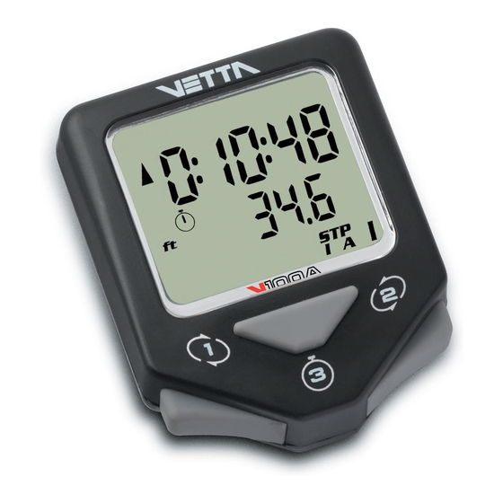
Page 4: V100A Illustrations
Vetta encourages you to ride safely. Wear a helmet every time • you ride, use front and rear lights at night, and always keep your eyes on the road ahead of you. V100A ILLUSTRATIONS HEAD UNIT: FRONT Main Display Upper Display... -
Page 5: Component Illustrations
HEAD UNIT: REAR Contact Pins Battery Compartment Battery Cover COMPONENT ILLUSTRATIONS... - Page 6 Wired Mounting Bracket Mounting Bracket Pad Riser Handle Bar Bracket Pad (You may choose B or C according to the style of your bicycle handlebar.) Spoke Magnet Spacer Wired Speed Sensor Wireless Active Mount WL Wireless Speed Transmitter Transmitter Mounting Pad Wired Cadence Sensor* Cadence Magnet* CR2032 3V Battery...
-
Page 7: Button Functions
BUTTON FUNCTIONS Button #1 Button #2 Button #3 SETUP MODE Button #1 Sets digits or units and advances to the next item or screen. Button #2 Advances digits and toggles through units. Hold for fast advance. Button #3 Has no function in Initial Setup. NORMAL OPERATING MODE Button #1 Scrolls through lower level screen symbols and... -
Page 8: V100A Screen Display Sequence: Bi-Level Memory
Hold simultaneously for 2 seconds in the ALT/% screen to enter Pre-Ride Altimeter Calibration Setup. V100A SCREEN DISPLAY SEQUENCE: BI-LEVEL MEMORY The V100 series computers are programmed with a Bi-Level Memory which returns to the last screen function accessed between the upper and lower screen modes. - Page 9 LOWER SCREEN UPPER SCREEN MODES MODES TOT ALT MAX ALT BI-LEVEL MEMORY SPD* ID/IA *(optional)
-
Page 10: V100A Primary Functions
V100A PRIMARY FUNCTIONS UPPER SCREEN MODES SPEED TRIP DISTANCE SPD displays the current Speed and is updated continuously. DST displays the current Trip Distance and automatically resets after the maximum trip distance (999.9) is achieved. Trip distance is displayed in the SPD/DST screen mode and starts automatically when the wheel rotates and TT Timer is active. -
Page 11: Average Speed Maximum Speed
seconds. Note: Whenever TT is activated, the stopwatch icon appears; otherwise it does not appear. The TT Timer must be active in order for the RT Timer to accumulate Ride Time and for the computer to calculate current ride data. CAUTION: If RT and TT timers are not 0:00:00 and you have stopped them manually, then they MUST be restarted manually by pressing Button #3 in the RT/TT mode. -
Page 12: Speed* Cadence
SPEED* CADENCE* When installed, the Cadence kit measures and displays pedal Cadence in Revolutions Per Minute (RPM). The SPD/CAD screen function letters appear ONLY when the Cadence hardware is installed and a Cadence signal received by the head unit. After a current ride data reset, (Button #3 for 2 seconds with the timers off ) the function letters will disappear, but they will come back on with the next... -
Page 13: Total Altitude Maximum Altitude
TOT ALT TOTAL ALTITUDE MAXIMUM ALTITUDE MAX ALT Total Altitude displays the cumulative altitude gain achieved for any given ride in feet or meters on the upper line. The Maximum Altitude or highest elevation attained during a ride is displayed on the lower line. Note: TOT ALT does not include descents. -
Page 14: Intermediate Distance
SPEED TEMPERATURE Current Temperature is displayed in the lower screen digits and updated once per minute. The thermometer icon illuminates when the Temperature display is active, and the right digit displays the scale selected in degrees Celsius "C" or degrees Fahrenheit "F". Below zero readings are indicated by a minus sign (-). -
Page 15: Stopwatch Intermediate Altitude
Stopwatch and ID functions; press Button #3 again to stop functions and freeze data for review. Reset Stopwatch, Intermediate Distance and Intermediate Altitude to zero by pressing Button #3 for 2 seconds. STOPWATCH INTERMEDIATE ALTITUDE Like the Intermediate Distance function described above, Intermediate Altitude tracks an intermediate climb within a longer ride and displays it on the lower line. -
Page 16: Dual Bike Memory
DUAL BIKE MEMORY The V100A can be calibrated for two bicycles. It will store separate Wheel Size, Service Timer, Odometer and Altitude settings, as well as different formats selected for Time, Temperature, Speed and Distance. The current bike number (I or II) is always displayed in the lower right corner of the screen. -
Page 17: Average Cadence* Maximum Cadence
MAXIMUM CADENCE* MAX CAD When the Cadence mounting kit is installed, the V100A displays both Average and Maximum Cadence in a secondary screen. Press and hold Button #1 in the SPD/CAD screen mode for 2 seconds. The Average and Maximum Cadence functions appear on the upper and lower lines respectively. -
Page 18: Service Timer, Low Battery Alert, Speed Comparator
(See SETUP section below for details.) LOW BATTERY ALERT The V100A Service Timer icon has been programmed to signal low battery power in the head unit. When the battery runs low and needs to be replaced, the Service Timer icon ( ) will illuminate and stay "on"... -
Page 19: Freeze Frame Memory
FREEZE FRAME MEMORY Freezes ride data from 5 primary screens SPD/DST for review at any point during a race or training ride. To activate Freeze Frame, press and hold Button #2 for 2 seconds SPD/DST in any primary screen mode. The screen will flash to indicate it has been frozen. -
Page 20: Auto Start
AUTO START If the RT/TT ride timers read zero (0:00:00), the Vetta V100A computer automatically starts as soon as it receives input from the wheel. The RT and TT timers are activated and other ride data begins to accumulate (SPD, DST, AVG & MAX SPD, CAD*, AVG &... -
Page 21: Ride Data Reset
RIDE DATA RESET To reset current ride, Freeze Frame and Altitude data to zero (DST, RT, TT, AVG & MAX SPD, AVG & MAX CAD*, TOT & MAX ALT, MAX % & MAX % (-), MAX & MIN TMP, STP, ID and IA), make sure the timers (RT/TT) are turned OFF and press Button #3 for 2 seconds in any primary screen mode except STP/ID or STP/IA. -
Page 22: Battery Installation
BATTERY INSTALLATION HEAD UNIT The V100A head unit uses a CR2032 3V lithium button cell battery. IMPORTANT: Most cycle computer problems are caused by weak or dead batteries. See the Troubleshooting section near the end of this manual for details. -
Page 23: Wl Wireless Speed Transmitter
WL WIRELESS SPEED TRANSMITTER The V100A WL wireless speed transmitter (signal from the wheel) uses an A23 12V battery. Remove cap, install battery with positive (+) side up, replace battery cap. CAUTION: Make sure the transmitter battery cap is properly installed to insure good signal transmission. -
Page 24: Setup Mode & Programming
SETUP MODE & PROGRAMMING INTRODUCTION After battery installation, the master screen will appear briefly and the computer will automatically go into the Initial Setup program mode. Note: To enter Setup when in the Normal Operating Mode (NOM), go to the SPD/DST screen mode and press Buttons #1 and #2 simultaneously for 2 seconds with the RT/TT timers off. - Page 25 Setup screen. Note: When programming a second bike in Initial Setup, scroll to "II", select it, and advance as instructed above. The V100A computer will retain the values and settings entered for Bike II independently of Bike I. SETUP: ALTITUDE UNITS...
- Page 26 SETUP: ALTIMETER ON/OFF This Setup screen allows you to turn the Altimeter function "ON" or "OFF" as you choose. The default setting for the Altimeter is "ON". Press Button #1 to select Altimeter "ON" and advance to the next screen. Or, if you don't want to activate the Altimeter function, press Button #2 to toggle to the "OFF"...
- Page 27 SETUP: ALTIMETER MEMORY 1 & 2 After Altimeter "ON" is selected, the computer advances to Altimeter Memory 1 Setup. This is the first of two Altimeter Memory settings in which the user can enter known elevation values to serve as quick, pre-ride Altimeter calibrations.
- Page 28 When programming Altimeter Memory 1, the number "1" appears just below the elevation figures (see illustration). When all the values for Altimeter Memory #1 have been set, press Button #1 to select it and advance to Altimeter Memory 2 setting. In this screen the number "2"...
- Page 29 WHEEL SIZE CALCULATION The circumference of the wheel is measured and entered in millimeters. Bike I and II wheel sizes are set independently, and both default to 2074mm (700c x 20 or 26 x 2.0). The following chart lists the circumference measurements for the most common wheel sizes.
- Page 30 SETUP: WHEEL CIRCUMFERENCE After Altimeter Memory 1 & 2 values have been selected and the display advances to the Wheel Size Setup screen, the letters "circ" appear on the lower level and the default numbers 2074 appear on the upper level with the right digit "4"...
- Page 31 SETUP: SERVICE TIMER The Service Timers, one for each bike, may be programmed with a select number of ride time hours as the interval for servicing the bicycle or any component on it, such as a front or rear shock. Accumulated Ride Time is displayed on the upper line and the Service Time interval is set and displayed on the lower line.
- Page 32 • To stop the Service Timer icon from flashing: A) Reset the accumulated Ride Time hours (upper line) to zero "0" through the NOM Setup sequence. The Service Timer interval may also be reprogrammed at this point. B) Change TT setting to a number larger than accumulated RT.
- Page 33 "C". Then press Button #1 to select and advance. SETUP: CLOCK The V100A clock displays time in either a 12 or 24 hour format. A "PM" indicator appears only in the 12hr format. To select a format and set the...
- Page 34 SETUP: ODOMETER Bike I and Bike II have separate, programmable odometers. On a new computer the Odometer screen should read "00000" for both. To confirm this initial zero setting, simply press Button #1 successively to select each flashing digit and advance to System Check.
- Page 35 To change any values or correct any unit errors made during Initial Setup, you must re-enter the Setup program in NOM by pressing Buttons #1 and #2 simultaneously for 2 seconds in the SPD/DST screen mode with the RT/TT timers deactivated. Note: System Check is activated in two ways: A) Automatically at the end of either Initial or NOM Setup and B) By pressing Button #3 at any time during NOM Setup.
-
Page 36: Pre-Ride Altimeter Calibration Setup
PRE-RIDE ALTIMETER CALIBRATION SETUP INTRODUCTION Before any new ride, the V100A Altimeter must be recalibrated so that it "knows" the correct starting elevation. Because elevation is calculated via barometric pressure, changes in barometric pressure detected by the sensor change the elevation displayed on the ALT/% screen. - Page 37 PRE-RIDE ALTIMETER CALIBRATION To calibrate the Altimeter, access the Pre-Ride Altimeter Calibration Setup program in NOM from the ALT/% screen. Press both Buttons #1 and #2 simultaneously for 2 seconds to enter the Setup screens for Altimeter Calibration. A) The first screen shows the Memory 1 Altimeter setting.
- Page 38 BAROMETRIC CALIBRATION The V100A Altimeter may also be calibrated by entering the current, local, barometric pressure at sea level either in Inches of Mercury (inHg) or in Millibars (mbar). To access the barometric entry screens, press Button #2 to bypass the Manual Altimeter Elevation input screen (See point C above).
- Page 39 3m in height. • For the same reason as above, the V100A may display zero or higher gradients; if the user climbs a short slope followed by descending another short slope.
- Page 40 V100A Cycle Computer will output and update Percent Grade (%) of uphill or downhill when the vertical displacement is greater than 3 meters. Example: 2% Gradients: Trip Distance Required, x=150 meters 5% Gradients: Trip Distance Required, x=60 meters 10% Gradients:...
-
Page 41: Installation Wired Model Installation
INSTALLATION WIRED MODEL INSTALLATION SPEED SENSOR & MAGNET NOTE: Wired cadence is optional. Please refer to WIRED SPEED AND CADENCE/WL2X DOUBLE WIRELESS SPEED AND CADENCE MANUAL for installation. Step 1: Use the zip-tie supplied to hold loosely the wired speed sensor and mounting pad to the inside of either fork leg. - Page 42 Fig. 1 Fig. 2 Spoke Zip Tie Magnet Magnet Sweep Path Spoke Magnet Spoke Wired Speed Fork Leg Sensor...
- Page 43 Fig. 3 Spoke Magnet Spoke Spacer Fig. 4 Spacer Alignment Mark Fig. 5 Spoke Magnet Wired Speed Sensor...
-
Page 44: Mounting Bracket
MOUNTING BRACKET Head Unit Wired Mounting Bracket Zip Tie Mounting Pad Handlebar Fig. 6 Install mounting pad and wired mounting bracket to the Step 1: handlebar using the 2 zip ties provided. (Fig. 6) Tighten the zip ties so that the mounting bracket holds Step 2: its position on the bars yet can be easily adjusted. -
Page 45: Head Unit
Handlebar Fig. 7 HEAD UNIT The V100A head unit is designed to slide into the mounting bracket from the front to the back and lock into position. You should hear an audible "CLICK" when the head unit has been properly locked into position. This indicates proper alignment between the computer head pins and the mounting bracket contacts. -
Page 46: Wireless Model Installation Speed Transmitter & Magnet
NOTE: WL2X Double wireless Speed & Cadence is optional. Please refer to WIRED SPEED AND CADENCE/WL2X DOUBLE The V100A is designed to operate as a wireless unit with the installation of a special active mount and WL wireless speed transmitter. - Page 47 Fig. 9 Fig. 10 Magnet Sweep Path Zip Ties Spoke Magnet Fork Leg Spoke Magnet Spoke...
- Page 48 Fig. 11 Spoke Magnet Spacer Spoke Fig. 12 Alignment Mark Spacer Fig. 13 Spoke Magnet Wireless Speed Transmitter...
-
Page 49: Active Mount
ACTIVE MOUNT Attach the active mount and mounting pad to the handlebar. Adjust its position to your liking and tighten the zip ties. (Fig. 14, Head Unit Wireless Active Mount Zip Tie Mounting Pad Handlebar Fig. 14... - Page 50 Head Unit Mounting Pad Handlebar Wireless Active Zip Tie Mount Fig. 15...
-
Page 51: Head Unit
HEAD UNIT The head unit is designed to slide into the wireless active mount from the front to the back and lock into position. You should hear an audible “CLICK” when the head unit has been properly locked into position. This indicates proper alignment between the computer head pins and the active mount contacts. -
Page 52: Installation Tests
If these checks do not solve the problem, talk to an Authorized Vetta Retailer or connect to www.vetta.com. IMPORTANT: Following the installation tests above, make sure that the spoke magnet locking screw and all zip ties are properly tightened. -
Page 53: Troubleshooting
TROUBLESHOOTING PROBLEM/ITEMS TO CHECK/SOLUTION • Current speed reading is erratic or does not appear. Check the alignment of the spoke magnet and sensor, and the distance between the two components. Realign the magnet and sensor with the spacer. Check to be sure RT and TT are activated. - Page 54 • Screen reading is weak or fading. Symptom of interference or a weak battery. Replace the battery. • Screen readings are erratic and read too high or too low. Symptom of a weak battery. Replace the battery. • Screen "frozen", no response to buttons. Symptom of a weak battery.
-
Page 55: Technical Specifications
TECHNICAL SPECIFICATIONS Current Speed (SPD) 0.0~120.0 KM/hr; 0.0~75.0 Mi/hr; +/-0.1 KM/hr or Mi/hr. Updated once per second. Average Speed (AVG) 0.0~120.0 KM/hr; 0.0~75.0 Mi/hr; +/-0.1 KM/hr or Mi/hr. Updated once every 0.1 Miles or Km traveled. Maximum Speed Limit: 120.0 KM/hr; 75.0 Mi/hr. (MAX) Odometer (ODO) 0~99999 km or miles. - Page 56 12 or 24 hour format, hours and Clock (CLK) minutes displayed. Limit: 1~1999 hrs. max; +/-1 hr. Service Timer Limit: 9:59:59 (10 hrs.); +/-1.0 Stopwatch (STP) seconds. Range: 999.9 km or miles. Intermediate Distance (ID) 5000 meter minus the current Intermediate Altitude (IA) altitude when activate the IA feature...
-
Page 57: Warranty Policy
God, improper installation or product alteration. This warranty is void if the components were not purchased (new) from or through an authorized VETTA retailer or dealer; examples of unauthorized dealers are online auction sites or online retailers that do not offer service. -
Page 58: Items To Be Included In Returns
The original owner may possess other rights or recourse, depending on the state or country. Please check the web to help answer any question and service manual. Acumen Inc. 101A Executive Dr., Suite 100, Sterling, VA 20166, USA. E-Mail: customerservice@vetta.com Website: www.vetta.com...
Need help?
Do you have a question about the V100A and is the answer not in the manual?
Questions and answers