
Subscribe to Our Youtube Channel
Related Manuals for Vetta V100HR


Summary of Contents for Vetta V100HR
-
Page 1: Table Of Contents
WARNINGS & CAUTIONS V100HR ILLUSTRATIONS HEAD UNIT COMPONENT ILLUSTRATIONS BUTTON FUNCTIONS SETUP MODE OPERATING MODE V100HR SCREEN DISPLAY SEQUENCE: BI-LEVEL MEMORY V100HR PRIMARY FUNCTIONS UPPER SCREEN MODES Speed, Trip Distance, Ride Time, Total Time Average Speed, Maximum Speed Speed*, Cadence*... - Page 2 AUDIBLE & VISUAL ALARMS RIDE DATA RESET ALL CLEAR TOTAL RESET TARGET ZONE & FITNESS TRAINING BATTERY INSTALLATION HEAD UNIT WL WIRELESS SPEED TRANSMITTER HEART RATE TRANSMITTER SETUP MODE & PROGRAMMING INSTALLATION WIRED MODEL INSTALLATION Speed Sensor & Magnet Mounting Bracket Head Unit WIRELESS MODEL INSTALLATION Speed Transmitter &...
-
Page 3: Introduction
Please take time to familiarize yourself with all the functions of the V100HR model so you can take full advantage of its programs. And don't forget to store this manual in a safe place... -
Page 4: Warnings & Cautions
Consult the manufacturer of the implant device and/or your physician prior to using this monitor. Vetta encourages you to ride safely. Wear a helmet every time • you ride, use front and rear lights at night, and always keep... -
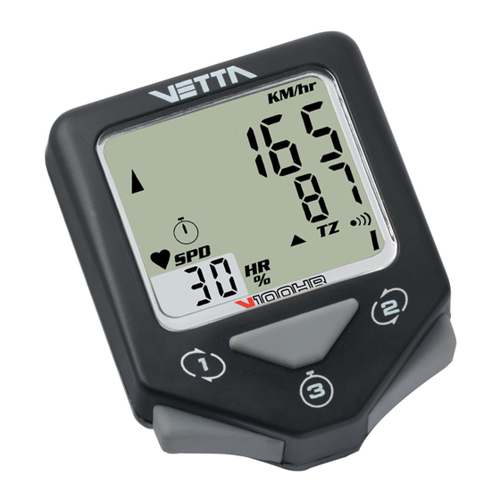
Page 5: V100Hr Illustrations
V100HR ILLUSTRATIONS HEAD UNIT: FRONT Main Display Upper Display Lower Display Audible Alarm Icon Lower Screen Symbols Upper and Lower Target Zone Symbols Sub-Display Average HR Symbol Sub-Display Speed Symbol Heart Rate/Speed Sub-Display Heart Rate Icon Stopwatch Icon Service Timer Icon... -
Page 6: Component Illustrations
HEAD UNIT: REAR Contact Pins Battery Compartment Battery Cover COMPONENT ILLUSTRATIONS... - Page 7 Wired Mounting Bracket Mounting Bracket Pad Riser Handle Bar Bracket Pad (You may choose B or C according to the style of your bicycle handlebar.) Spoke Magnet Spacer Wired Speed Sensor Wireless Active Mount WL Wireless Speed Transmitter Transmitter Mounting Pad Wired Cadence Sensor* Cadence Magnet* CR2032 3V Battery...
-
Page 8: Button Functions
BUTTON FUNCTIONS Button #1 Button #2 Button #3 SETUP MODE Button #1 Sets digits or units and advances to the next item or screen. Button #2 Advances digits and toggles through units. Hold for fast advance. Button #3 Has no function in Initial Setup. -
Page 9: Operating Mode
Hold simultaneously for 2 seconds in the HR/% screen mode to enter NOM Setup for heart rate functions. V100HR SCREEN DISPLAY SEQUENCE: BI-LEVEL MEMORY The V100 series computers are programmed with a Bi-Level Memory which returns to the last screen function accessed between the upper and lower screen modes. - Page 10 LOWER SCREEN UPPER SCREEN MODES MODES BI-LEVEL MEMORY SPD* *(Optional)
-
Page 11: V100Hr Primary Functions
V100HR PRIMARY FUNCTIONS UPPER SCREEN MODES SPEED TRIP DISTANCE SPD displays the current Speed and is updated continuously. DST displays current Trip Distance and automatically resets after the maximum trip distance (999.9) is achieved. Trip Distance is displayed in the... -
Page 12: Average Speed Maximum Speed
of a ride. To reset both RT and TT to zero, turn the timers off and press Button #3 for at least 2 seconds. Note: Whenever TT is activated, the stopwatch icon appears; otherwise it does not appear. The TT Timer must be active in order for the RT Timer to accumulate Ride Time and for the computer to calculate current ride and heart rate memory data. -
Page 13: Speed* Cadence
SPEED* CADENCE* When installed, the Cadence kit measures and displays pedal Cadence in Revolutions Per Minute (RPM). The SPD/CAD screen function letters appear ONLY when the Cadence hardware is installed and a Cadence signal received by the head unit. After a current ride data reset, (Button #3 for 2 seconds with timers off) the function letters will disappear, but they will will come back on with the next... -
Page 14: Intermediate Distance
CLOCK ODOMETER The time is displayed in the CLK/ODO screen mode and features a user selectable 12 or 24 hour format. Odometer displays cumulative distance until an All Clear Total Reset is performed, the battery is changed*, or the ride distance exceeds the maximum limit, after which the Odometer will *Note: automatically... -
Page 15: Dual Bike Memory, Heart Rate Reading
DUAL BIKE MEMORY The V100HR can be calibrated for two bicycles. It will store separate Wheel Size, Service Timer, Odometer, Age and Heart Rate Target Zone settings, as well as different formats for Time, Speed and Distance. The current bike number (I or II) is always displayed in the lower right corner of the screen. -
Page 16: V100Hr Secondary Functions & Features
AVERAGE CADENCE* AVG CAD MAXIMUM CADENCE* MAX CAD When the V100HR is attached to a cadence mount, it displays both Average and Maximum Cadence in a secondary screen. Press and hold Button #1 in the SPD/CAD screen mode for 2 seconds. Average and Maximum Cadence appear on the upper and lower lines respectively. -
Page 17: Low Battery Alert, Speed Comparator
LOW BATTERY ALERT The V100HR Service Timer icon has been programmed to signal low battery power in the head unit. When the battery runs low and needs to be replaced, the Service Timer icon ( ) will illuminate and stay "on" (no blinking). -
Page 18: Freeze Frame Memory
FREEZE FRAME MEMORY Freezes ride data from 4 primary screens for review at any point during a SPD/DST race or training ride. To activate Freeze Frame, press and hold Button #2 for 2 seconds in any primary screen mode. SPD/DST The screen will flash to indicate it has been frozen. -
Page 19: Heart Rate Memory Storage & Recall
HEART RATE MEMORY STORAGE & RECALL At the end of your ride or workout, or at any point during a race or training ride, this feature freezes heart rate data for review in a 4 screen sequence. To activate Heart Rate Memory Storage and Recall, start from the HR/% screen mode and press and hold Button #1 for 2 seconds. -
Page 20: Auto Start
Recall at any time, press Button #1 and return to the primary HR/% screen mode. AUTO START If the RT/TT timers read zero (0:00:00), the Vetta V100HR computer automatically starts as soon as it receives input from the wheel. The RT and TT timers are activated and other ride data begins to accumulate (SPD, DST, AVG &... -
Page 21: Audible & Visual Alarms
*Note: Wired version only. In the wireless version the computer will "wake up" only when one of the buttons is pushed. AUDIBLE & VISUAL ALARMS The V100HR features both Audible ( ) and Visual HR Target Zone Alarms. These alarms signal when the user's heart rate rises above or falls below the pre-established HR Target Zone during an exercise session. -
Page 22: Target Zone & Fitness Training
In most cases they will come up with a range very close to or the same as the auto-setting of the V100HR. If you prefer to fine-tune or program your own limits, this can also be done in the HR Setting Mode (see page 30). - Page 23 TARGET ZONE CALCULATION FORMULA 220 - Your age = max HR For a 30 year old person, your calculations would be as follows: 220 - 30 = 190 Maximum Heart Rate 65% of this number = 124 85% of this number = 162 The calculated exercise range for a 30 year old would be a low of 124 and a high of 162 beats per minute.
- Page 24 STRETCHING Begin and end every workout with stretching. Stretching done before your workout increases flexibility to help prevent muscle strain or injury and stretching after, loosens tight muscles and helps prevent soreness. • Stretch before warm up and after cool down. •...
- Page 25 THE AEROBIC ZONE: 65-85% This range is recommended for those in good physical condition who have been exercising on a consistent basis for an extended period of time. Exercising at this range helps improve your fitness level and prevent injury caused from over training. Duration: 20-30 min.
-
Page 26: Battery Installation
BATTERY INSTALLATION HEAD UNIT The V100HR head unit uses a CR2032 3V lithium button cell battery. IMPORTANT: Most cycle computer problems are caused by weak or dead batteries. See the Troubleshooting section near the end of this manual for details. -
Page 27: Wl Wireless Speed Transmitter
WL WIRELESS SPEED TRANSMITTER The V100HR WL wireless speed transmitter (signal from the wheel) uses an A23 12V battery. Remove cap, install battery with positive (+) side up, replace battery cap. CAUTION: Make sure the transmitter battery cap is properly installed to... -
Page 28: Heart Rate Transmitter
HEART RATE TRANSMITTER The Vetta heart rate transmitter comes with the battery (CR2032 3V lithium) already installed. Note: This battery is user replaceable. SETUP MODE & PROGRAMMING INTRODUCTION After battery installation, the master screen will appear briefly and the computer will automatically go into the Initial Setup program mode. - Page 29 Button #1 to select it and advance to the Note: "Age" Setup screen. When programming a second bike in Initial Setup, scroll to "II", select it, and advance as instructed above. The V100HR computer will retain the values and settings entered for Bike II independently of Bike I.
- Page 30 The Initial Age Setup has a range of 7 to 99 years of age, and the default age setting is 18 years. When you enter your age, the V100HR computer will automatically calculate your Maximum Heart Rate in order to establish a heart rate "Target Zone"...
- Page 31 Step 3: Target Zone Upper Limit (blinking): After Maximum HR has been selected and set, the computer automatically calculates an initial HR Target Zone Upper Limit setting (85% of max HR) and displays it on the upper line in blinking numbers. The letters "TZ"...
- Page 32 Limit by pressing Button #1, the computer will automatically advance to the Audible Alarm setting screen mode. The V100HR has a Visual Target Zone Alarm that is always active, but you can turn the Audible Alarm on or off as desired.
- Page 33 WHEEL SIZE CALCULATION The circumference of the wheel is measured and entered in millimeters. Bike I and II wheel sizes are set independently, and both default to 2074mm (700c x 20 or 26 x 2.0). The following chart lists the circumference measurements for the most common wheel sizes.
- Page 34 SETUP: WHEEL CIRCUMFERENCE After the Audible Alarm has been set and the display advances to the Wheel Size Setup screen, the letters "circ" appear on the lower level and the default numbers 2074 appear on the upper level with the right digit "4" flashing.
- Page 35 SETUP: SERVICE TIMER The Service Timers, one for each bike, may be programmed with a select number of ride time hours as the interval for servicing the bicycle or any component on it, such as a front or rear shock. Accumulated Ride Time is displayed on the upper line and the Service Time interval is set and displayed on the lower line.
- Page 36 SERVICE TIMER NOTES • Accumulated Ride Time (upper line) operates in conjunction with the other timers and starts as soon as the wheel turns. It stops automatically when the computer receives no input from the wheel for 3 seconds. • The Service Timer screen can be viewed in both the NOM Setup for cycling and in the System Check screen sequence.
- Page 37 "KM" flashing. Press Button #1 to select and advance. SETUP: CLOCK The V100HR clock displays time in either a 12 or 24 hour format. A "PM" indicator appears only in the 12hr format. To select a format and set the current time, proceed as follows:...
- Page 38 SETUP: ODOMETER Bike I and Bike II have separate, programmable odometers. On a new computer the Odometer screen should read "00000" for both. To confirm this initial zero setting, simply press Button #1 successively to select each flashing digit and advance to System Check. To reenter mileage achieved after a battery change, follow these steps: Step 1:...
- Page 39 SETUP: SYSTEM CHECK After the Programmable Odometer is set, both the Initial and Normal Operating Mode Setup programs will automatically advance to the System Check screen sequence. System Check displays all value and unit settings chosen during Setup in a 6 screen sequence.
-
Page 40: Installation Wired Model Installation
To change any value or correct any unit errors made during Initial Setup, you must re-enter one of the two NOM Setup programs in the V100HR. The first NOM Setup program covers heart rate specific functions and the second covers cycling specific functions and features. - Page 41 Step 4: Slide and rotate the sensor until the alignment mark just touches the spacer tip on the magnet. (Fig. 4) Route the sensor wire up the fork blade and secure it Step 5: with the tape. Wrap excess wire around the front brake cable housing, leaving enough slack to attach the mounting bracket easily to the handlebar and allow for movement of the bar and stem.
- Page 42 Fig. 1 Fig. 2 Spoke Zip Tie Magnet Magnet Sweep Path Spoke Magnet Spoke Wired Speed Fork Leg Sensor...
- Page 43 Fig. 3 Spoke Magnet Spoke Spacer Fig. 4 Spacer Alignment Mark Fig. 5 Spoke Magnet Wired Speed Sensor...
-
Page 44: Mounting Bracket
MOUNTING BRACKET Head Unit Wired Mounting Bracket Zip Tie Mounting Pad Handlebar Fig. 6 Step 1: Install mounting pad and wired mounting bracket to the handlebar using the 2 zip ties provided. (Fig. 6) Step 2: Tighten the zip ties so that the mounting bracket holds its position on the bars yet can be easily adjusted. -
Page 45: Head Unit
Zip Tie Handlebar HEAD UNIT The V100HR head unit is designed to slide into the mounting bracket from the front to the back and lock into position. You should hear an audible "CLICK" when the head unit has been properly locked into position. This indicates proper alignment between the computer head pins and the mounting bracket contacts. -
Page 46: Wireless Model Installation
NOTE: WL2X Double wireless Speed & Cadence is optional. Please refer to WIRED SPEED AND CADENCE/WL2X DOUBLE WIRELESS SPEED AND CADENCE MANUAL for installation. The V100HR is designed to operate as a wireless unit with the installation of a special active mount and WL wireless speed transmitter. - Page 47 Fig. 9 Fig. 10 Magnet Sweep Path Zip Ties Spoke Magnet Fork Leg Spoke Magnet Spoke...
- Page 48 Fig. 11 Spoke Magnet Spacer Spoke Fig. 12 Alignment Mark Spacer Fig. 13 Spoke Magnet WL Wireless Speed Transmitter...
-
Page 49: Active Mount
ACTIVE MOUNT Attach the active mount and mounting pad to the handlebar. Adjust its position to your liking and tighten the zip ties. (Fig. 14, 15) Head Unit Wireless Active Mount Zip Tie Mounting Pad Handlebar Fig. 14... -
Page 50: Head Unit
Fig. 15 Head Unit Mounting Pad Handlebar Wireless Active Zip Tie Mount HEAD UNIT The head unit is designed to slide into the wireless active mount from the front to the back and lock into position. You should hear an audible “CLICK” when the head unit has been properly locked into position. -
Page 51: Installation Tests
If these checks do not solve the problem, talk to an Authorized Vetta Retailer, or connect to www.vetta.com. -
Page 52: Attaching Your Heart Monitor
IMPORTANT: Following the installation tests above, make sure that the spoke magnet locking screw and all zip ties are properly tightened. Tips: Rotating the angle of the transmitters or the handlebar receiver (slightly), can sometimes improve the signals being sent and received. - Page 53 Fig. 18 Step 3: Center and position the belt as shown, at heart level, just below your pectoral muscles or breasts (but not too low) and attach the other end of the strap to the transmitter. The logo should be positioned at the center of your chest.
-
Page 54: Troubleshooting Problem/Items To Check/Solution: Cycling
If you prefer to wear your belt over a light shirt you will need to generously moisten the areas of the shirt directly beneath the electrodes in order to insure proper signal pick-up. You may wear as many layers of clothing as desired over the transmitter belt without affecting the operating range. -
Page 55: Problem/Items To Check/Solution: Heart
• Screen readings are erratic and read too high or too low. Symptom of a weak battery. Replace the battery. • Screen "frozen", no response to buttons. Symptom of a weak battery. Replace the battery. • No display whatsoever. Battery is completely dead, or not installed. Replace or install the battery. -
Page 56: Care & Maintenance
If this occurs, you should first try an All Clear Total Reset. Otherwise send it in for service. Repairs should only be done by Vetta or an Authorized Vetta Dealer. • Stuck or Erratic Display? -
Page 57: Battery Replacement
Should your chest transmitter need battery replacement, we recommend that you take it to a local jewelry store or an Authorized Vetta Dealer in order to guarantee that it will maintain its water resistance. Improper battery replacement or service will void the warranty. - Page 58 Limit: 1~1999 hrs. max; +/-1 hr. Service Timer Stopwatch Limit: 9:59:59 (10 hrs.); +/-1.0 seconds. Heart Rate Range: 40~240 BPM. Intermediate Distance Range: 999.9 km or miles. (IDS) Ride/Total Time (RT/TT) Limit: 9:59:59 (10 hours) displayed in hr/min/sec. After 9:59:59, display restarts at "0:00:00".
-
Page 59: Warranty Policy
RA#. 2. To obtain an RA #, you must either contact the retailer where the product was originally purchased from, or contact VETTA directly at customerservice@vetta.com. 3. For trouble shooting purposes, we request that the complete unit with packaging be returned to ACUMEN INC. -
Page 60: Items To Be Included In Returns
The original owner may possess other rights or recourse, depending on the state or country. Please check the web to help answer any question and service manual. Acumen Inc. 101A Executive Dr., Suite 100, Sterling, VA 20166, USA. E-Mail: customerservice@vetta.com Website: www.vetta.com...
Need help?
Do you have a question about the V100HR and is the answer not in the manual?
Questions and answers