
Related Manuals for Vetta V100


Summary of Contents for Vetta V100
-
Page 1: Table Of Contents
WARNINGS & CAUTIONS V100 ILLUSTRATIONS HEAD UNIT COMPONENT ILLUSTRATIONS BUTTON FUNCTIONS SETUP MODE OPERATING MODE V100 SCREEN DISPLAY SEQUENCE: BI-LEVEL MEMORY V100 PRIMARY FUNCTIONS UPPER SCREEN MODES Speed,Trip Distance, Ride Time,Total Time Average Speed, Maximum Speed, Speed*, Cadence* LOWER SCREEN MODES... - Page 2 AUTO START SLEEP MODE RIDE DATA RESET ALL CLEAR TOTAL RESET BATTERY INSTALLATION HEAD UNIT WL WIRELESS SPEED TRANSMITTER SETUP MODE & PROGRAMMING INSTALLATION WIRED MODEL INSTALLATION Speed Sensor & Magnet Mounting Bracket Head Unit WIRELESS MODEL INSTALLATION Speed Transmitter & Magnet Active Mount Head Unit INSTALLATION TESTS...
-
Page 3: Introduction
INTRODUCTION Thank you for purchasing a Vetta V100 cycle computer. The V100 series computers represent the latest evolution in Vetta's computer line and are designed for cycling enthusiasts and competitive cyclists alike. In particular, the V100 model offers a wide range of unique features and functions such as Temperature, Dual Bike Memory, Intermediate Distance and Stopwatch readings and a Service Timer. -
Page 4: V100 Illustrations
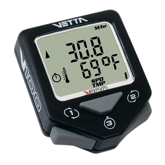
V100 ILLUSTRATIONS HEAD UNIT: FRONT Main Display Upper Display Lower Display Lower Screen Symbols Temperature Icon Service Timer Icon Stopwatch Icon Speed Comparator Symbol Upper Screen Symbols Button #1 (Left) Button #2 (Right) Button #3 (Center) -
Page 5: Component Illustrations
HEAD UNIT: REAR Contact Pins Battery Compartment Battery Cover COMPONENT ILLUSTRATIONS... - Page 6 Wired Mounting Bracket Mounting Bracket Pad Riser Handle Bar Bracket Pad (You may choose B or C according to the style of your bicycle handlebar.) Spoke Magnet Spacer Wired Speed Sensor Wireless Active Mount WL Wireless Speed Transmitter Transmitter Mounting Pad Wired Cadence Sensor* Cadence Magnet* CR2032 3V Battery...
-
Page 7: Button Functions
BUTTON FUNCTIONS Button #1 Button #2 Button #3 SETUP MODE Button #1 Sets digits or units and advances to the next item or screen. Button #2 Advances digits and toggles through units. Hold for fast advance. Button #3 Has no function in Initial Setup. OPERATING MODE Scrolls through lower level screen symbols and Button #1... -
Page 8: V100 Screen Display Sequence: Bi-Level Memory
#1 and #2 simultaneously for 2 seconds. V100 SCREEN DISPLAY SEQUENCE: BI-LEVEL MEMORY The V100 series computers are programmed with a Bi-Level Memory which returns to the last screen function accessed between the upper and lower screen modes. See illustration for this sequence and... - Page 9 LOWER SCREEN UPPER SCREEN MODES MODES BI-LEVEL MEMORY SPD* *(optional)
-
Page 10: V100 Primary Functions
V100 PRIMARY FUNCTIONS UPPER SCREEN MODES SPEED TRIP DISTANCE SPD displays the current Speed and is updated continuously. DST displays current Trip Distance. Automatically resets after the maximum trip distance (999.9) is achieved. Trip Distance is displayed in the SPD/DST screen mode and starts automatically when the wheel rotates and TT timer is active. -
Page 11: Average Speed Maximum Speed
Note: Whenever TT is activated, the stopwatch icon appears; otherwise, it does not display. CAUTION : If RT and T T timers are not 0:00:00 and you have stopped them manually, then they MUST be restarted manually by pressing Button #3 in RT/TT mode. If not, the computer will not record speed or other ride data. -
Page 12: Lower Screen Modes
LOWER SCREEN MODES CLOCK ODOMETER The time is displayed in the CLK/ODO screen mode and features a user selectable 12 or 24 hour format. Odometer displays cumu-lative distance until an All Clear Total Reset is performed, the battery is changed*, or the ride distance exceeds the maximum limit, after which the Odometer will automatically reset to zero. -
Page 13: Stopwatch Intermediate Distance
Stopwatch and IDS to zero by pressing Button #3 for 2 seconds. DUAL BIKE MEMORY The V100 can be calibrated for two bicycles. It will store separate Wheel Size and Service Timer settings, Odometer settings and formats selected for Time, Temperature, Speed and Distance. -
Page 14: V100 Secondary Functions & Features
Suspension forks, rear shocks, chains, etc. require service at specific time intervals set by manufacturers. Vetta’s Service Timer allows the rider to preset an exact number of riding hours during Setup, then signals (slow, flashing wrench icon) when the service time limit has been reached. -
Page 15: Average Cadence* Maximum Cadence
AVERAGE CADENCE* AVG CAD MAXIMUM CADENCE* MAX CAD The V100 displays both Average and Maximum Cadence in a secondary screen. Press and hold Button #1 in the SPD/CAD screen mode for 2 seconds. Average and Maximum Cadence appear on the upper and lower lines respectively. -
Page 16: Freeze Frame Memory
). AUTO START If the RT/TT timers read zero (0:00:00), the Vetta V100 computer automatically starts as soon as it receives input from the wheel. The RT and TT timers are activated and other ride data begins to accumulate (SPD, DST, AVG &... -
Page 17: Sleep Mode
To conserve battery life, the V100 computer is programmed to enter a Sleep Mode after receiving no input from buttons, wheel motion or cadence for 5 minutes. In this mode, the V100 screen displays only the time of day. The computer exits Sleep Mode automatically when... -
Page 18: Battery Installation
BATTERY INSTALLATION HEAD UNIT The V100 head unit uses a CR2032 3V lithium button cell battery. IMPORTANT: Most cycle computer problems are caused by weak or dead batteries. See the Troubleshooting section near the end of this manual for details. -
Page 19: Wl Wireless Speed Transmitter
WL WIRELESS SPEED TRANSMITTER The V100 WL wireless speed transmitter uses an A23 12V battery. Remove cap, install battery with positive (+) side up, replace battery cap. -
Page 20: Setup Mode & Programming
Setup screen. Note: When programming a second bike in Setup, scroll to “II” , select it, and advance as instructed above. The V100 computer will retain the values and settings entered for Bike II independently of Bike I. - Page 21 WHEEL SIZE CALCULATION The circumference of the wheel is measured and entered in millimeters. Bike I and II wheel sizes are set independently, and both default to 2074mm (700c x 20 or 26 x 2.0). The following chart lists the circumference measurements for the most common wheel sizes.
- Page 22 SETUP: WHEEL CIRCUMFERENCE After the bike number is selected and the display advances to the Wheel Size Setup screen, “circ” appears in small letters on the lower level and the default numbers 2074 appear on the upper level with the right digit “4”...
- Page 23 SETUP: SERVICE TIMER The Service Timers, one for each bike, may be programmed with a select number of ride time hours as the interval for servicing the bicycle or any component on it, such as a front or rear shock. Accumulated Ride Time is displayed on the upper line and the Service Time interval is set and displayed on the lower line.
- Page 24 To stop the Service Timer icon from flashing: A) Reset the • accumulated Ride Time hours (upper line) to zero “0” through the NOM Setup sequence. The Service Timer interval may also be reprogrammed at this point. B) Change TT setting to a number larger than accumulated RT.
- Page 25 “C". Then press Button #1 to select and advance. SETUP: CLOCK The V100 clock displays time in either a 12 or 24 hour format. A "PM" indicator appears only in the 12hr format. To select a format and set the...
- Page 26 SETUP: ODOMETER Bike I and Bike II have separate odometers. On a new computer the Odometer screen should read “00000” for both. To confirm this initial zero setting, simply press Button #1 successively to select each flashing digit and advance to System Check.
-
Page 27: Installation Wired Model Installation
Note: System Check is activated in two ways: 1) By pressing Button #3 any time during NOM Setup and 2) Automatically at the end of either Initial or NOM Setup. To exit NOM System Check manually and enter Normal Operating Mode, press Button #3 to return to the SPD/DST primary screen mode. - Page 28 alignment mark on the sensor. (Fig. 1, 2) Step 3: Attach the alignment setup spacer to the magnet temporarily. (Fig. 3) Step 4: Slide and rotate the sensor until the alignment mark just touches the spacer tip on the magnet. (Fig. 4) Step 5: Route the sensor wire up the fork blade and secure it with the tape.
- Page 29 Fig. 1 Fig. 2 Spoke Zip Tie Magnet Magnet Sweep Path Spoke Magnet Spoke Wired Speed Fork Leg Sensor...
- Page 30 Fig. 3 Spoke Magnet Spoke Spacer Fig. 4 Spacer Alignment Mark Fig. 5 Spoke Magnet Wired Speed Sensor...
-
Page 31: Mounting Bracket
MOUNTING BRACKET Head Unit Wired Mounting Bracket Zip Tie Mounting Pad Handlebar Fig. 6 Step 1: Install mounting pad and wired mounting bracket to the handlebar using the 2 zip ties provided. (Fig. 6) Step 2: Tighten the zip ties so that the mounting bracket holds its position on the bars yet can be easily adjusted. -
Page 32: Head Unit
Zip Tie Handlebar HEAD UNIT The V100 head unit is designed to slide into the mounting bracket from the front to the back and lock into position. You should hear an audible “CLICK” when the head unit has been properly locked into position. This indicates proper alignment between the computer head pins and the mounting bracket contacts. -
Page 33: Wireless Model Installation Speed Transmitter & Magnet
NOTE: WL2X Double wireless Speed & Cadence is optional. Please refer to WIRED SPEED AND CADENCE/WL2X DOUBLE The V100 is designed to operate as a wireless unit with the installation of a special active mount and WL wireless speed transmitter. - Page 34 Fig. 9 Fig. 10 Magnet Sweep Path Zip Ties Spoke Magnet Fork Leg Spoke Magnet Spoke...
- Page 35 Fig. 11 Spoke Magnet Spacer Spoke Fig. 12 Alignment Mark Spacer Fig. 13 Spoke Magnet WL Wireless Speed Transmitter...
-
Page 36: Active Mount
ACTIVE MOUNT Attach the active mount and mounting pad to the handlebar. Adjust its position to your liking and tighten the zip ties. CAUTION: Do not over tighten the zip ties on the active mount because this may bend the bracket and affect the operation of the computer. - Page 37 Fig. 15 Head Unit Mounting Pad Handlebar Wireless Active Zip Tie Mount...
-
Page 38: Head Unit
HEAD UNIT The head unit is designed to slide into the wireless active mount from the front to the back and lock into position. You should hear an audible “CLICK” when the head unit has been properly locked into position. This indicates proper alignment between the computer head pins and the active mount contacts. -
Page 39: Installation Tests
If these checks do not solve the problem, talk to an Authorized Vetta Retailer or connect to www.vetta.com. IMPORTANT: Following the installation tests above, make sure that the spoke magnet locking screw and all zip ties are properly tightened. - Page 40 • Current speed reading is erratic or does not appear. Inspect the wiring for any breaks or kinks. Replace the mounting bracket and sensor as needed. • Incorrect data appears on screen during operation. Accuracy of the Setup data may be a problem (wheel circumference setting, bike #, etc.).
-
Page 41: Technical Specifications
TECHNICAL SPECIFICATIONS TECHNICAL SPECIFICATIONS Current Speed (SPD) 0.0~120.0 KM/hr; 0.0~75.0 Mi/hr; +/-0.1 KM/hr or Mi/hr. Updated once per second. Average Speed (AVG) 0.0~120.0 KM/hr; 0.0~75.0 Mi/hr; +/-0.1 KM/hr or Mi/hr. Updated once every 0.1 Miles or Km traveled. Limit: 120.0 KM/hr; 75.0 Mi/hr. Maximum Speed (MAX) Odometer (ODO) 0~99999 km or miles. - Page 42 Limit: 1~1999 hrs. max; +/-1 hr. Service Timer Limit: 9:59:59 (10 hrs.); +/-1.0 seconds. Stopwatch Range: 999.9 km or miles. Intermediate Distance (IDS) Limit: 9:59:59 (10 hours) displayed in Ride/Total Time (RT/TT) hr/min/sec. After 9:59:59, display restarts at "0:00:00". Range: 15~255 RPM; +/-1 RPM. Cadence (RPM) (optional) Head Unit: CR2032 3 volt battery.
-
Page 43: Warranty Policy
God, improper installation or product alteration. This warranty is void if the components were not purchased (new) from or through an authorized VETTA retailer or dealer; examples of unauthorized dealers are online auction sites or online retailers that do not offer service. -
Page 44: Items To Be Included In Returns
The original owner may possess other rights or recourse, depending on the state or country. Please check the web to help answer any question and service manual. Acumen Inc. 101A Executive Dr., Suite 100, Sterling, VA 20166, USA. E-Mail: customerservice@vetta.com Website: www.vetta.com...
Need help?
Do you have a question about the V100 and is the answer not in the manual?
Questions and answers