Table of Contents
Advertisement
Quick Links
Operating instructions
Solenoid Metering Pump
Beta
b BT4b and BT5b
®
Please carefully read these operating instructions before use! · Do not discard!
The operator shall be liable for any damage caused by installation or operating errors!
Technical changes reserved.
Part no. 986356
Original Operating Instructions (2006/42/EC)
BA BE 026 04/12 EN
Advertisement
Table of Contents

Related Manuals for ProMinent Beta BT4b


Summary of Contents for ProMinent Beta BT4b
-
Page 1: Operating Instructions
Operating instructions Solenoid Metering Pump Beta b BT4b and BT5b ® Please carefully read these operating instructions before use! · Do not discard! The operator shall be liable for any damage caused by installation or operating errors! Technical changes reserved. Part no. - Page 2 ProMinent Dosiertechnik GmbH Im Schuhmachergewann 5-11 D-69123 Heidelberg Telephone: +49 6221 842-0 Fax: +49 6221 842-617 email: info@prominent.com Internet: www.prominent.com 986357, 3, en_GB © 2009...
- Page 3 Safety notes are identified by pictograms - see Safety Chapter. General user instructions Two sets of operating instructions are required for the safe, correct and proper operation of the metering pumps: The product-specific operating instructions and the "General Operating Instructions for ProMinent Sole‐ ® noid Metering Pumps".
-
Page 4: Table Of Contents
Table of contents Table of contents Identity code ................... 6 About this pump................8 Safety chapter................. 9 Storage, transport and unpacking..........14 Overview of equipment and control elements....... 16 5.1 Overview of equipment............16 5.2 Control elements..............17 5.2.1 Pulse Control Switch............17 5.2.2 Stroke length adjustment knob........... - Page 5 Table of contents 13.3 Warning Alerts..............43 13.4 All Other Faults..............43 Decommissioning................44 Technical data................46 15.1 Performance data..............46 15.2 Accuracy................47 15.2.1 Standard Liquid End............47 15.2.2 Self-Bleeding Liquid End..........48 15.3 Viscosity................48 15.4 Material Data............... 48 15.5 Electrical data..............
-
Page 6: Identity Code
Identity code Identity code Product range Beta b Type Performance 1000 0.74 1601 1.10 1602 2.20 1604 3.60 0708 7.10 0413 12.30 0220 19.00 2504 2.90 1008 6.80 0713 11.00 0420 17.10 0232 32.00 Material of dosing head/valves Polypropylene/PVDF. With the self-bleeding version (SEK): polypropylene/polypropylene Clear acrylic/PVDF. - Page 7 Identity code Product range Beta b Design Standard Logo with ProMinent logo Electrical connection 100-230 V ± 10 %, 50/60 Hz Cable and plug 2 m European 2 m Swiss 2 m Australian 2 m USA 2 m open end...
-
Page 8: About This Pump
About this pump About this pump Properties of the device This solenoid metering pump Beta b is equipped with all adjustment and activation functions for modern water treatment and the dosing of chemi‐ cals. It has pulse step-up and pulse step-down compared with the pre‐ ceding model. -
Page 9: Safety Chapter
Observe the general limitations with regard to viscosity limits, chem‐ ical resistance and density - see also ProMinent ® resistance list (In the product equipment catalogue or at www.prominent.com... - Page 10 Safety chapter Safety notes WARNING! Warning about personal and material damage The pump can start to pump, as soon as it is connected to the mains voltage. – Install an emergency cut-off switch in the pump power supply line or integrate the pump in the emergency cut- off management of the system.
- Page 11 – Take into account the resistance of the materials which will come into contact with the chemical when selecting the feed chemical - see the ProMinent product catalogue www.prominent.com . or under CAUTION! Warning of feed chemical spraying around The metering pump can generate a multiple of its rated pres‐...
- Page 12 Hood (houses the control elements) The dosing head may only be removed by the customer in accordance with the "Repair" chapter. The housing and the hood may only be removed by ProMinent customer service department. Information in the event of an emergency...
- Page 13 Service Customer Service department refers to service technicians, who have received proven training and have been authorised by ProMinent or Pro‐ Maqua to work on the system. Sound pressure level Sound pressure level LpA < 70 dB in accordance with EN ISO...
-
Page 14: Storage, Transport And Unpacking
WARNING! The transporting of pumps which have been used with radio‐ active feed chemicals is forbidden! They will also not be accepted by ProMinent! WARNING! Only return the metering pump for repair in a cleaned state and with a flushed liquid end - refer to the section on decom‐... - Page 15 Storage, transport and unpacking Scope of supply Compare the delivery note with the scope of supply: Metering pump with mains power cable Connector kit for tube/pipe connection Product-specific operating instructions with EC Declaration of Con‐ formity CD with order information, exploded diagrams, performance diagrams and data sheets Optional accessories if ordered...
-
Page 16: Overview Of Equipment And Control Elements
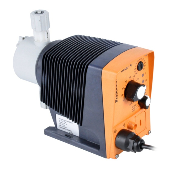
Overview of equipment and control elements Overview of equipment and control elements 5.1 Overview of equipment P_BE_0013_SW Fig. 2: Complete overview Control unit Drive unit Liquid end P_BE_0008_SW Fig. 3: Overview of liquid end (PV) Discharge valve Backplate Dosing head Bleed valve Bypass hose nozzle Suction valve... -
Page 17: Control Elements
Overview of equipment and control elements 5.2 Control elements P_BE_0011_SW Fig. 4 Pulse Control Switch Stroke length adjustment knob Fault indicator (red) Warning indicator (yellow) Operating indicator (green) Multifunctional switch "External control" terminal Relay connection (optional) "Level Switch" terminal 5.2.1 Pulse Control Switch In Extern Contact operating mode via the pulse control switch a single contact (at the "external control"... -
Page 18: Functional And Fault Indicators
Overview of equipment and control elements 5.2.4 Functional and Fault Indicators Fault indicator (red) The fault indicator lights up if the liquid level in the chemical feed container falls below the second switching point of the level switch (20 mm residual filling level in the chemical feed container). -
Page 19: Functional Description
Functional description Functional description 6.1 Liquid End The dosing process is performed as follows: The diaphragm is pressed into the dosing head; the pressure in the dosing head closes the suction valve and the feed chemical flows through the discharge valve out of the dosing head. -
Page 20: Functions
Functional description 6.6 Functions The functions are described below in the "Operation" chapter. 6.7 Relay The pump has two connecting options. Fault indicating relay option The relay can switch a connected power circuit (e.g. for an alarm horn) in the event of warnings or fault messages (e.g. warning levels). The relay can be retrofitted with the retrofit kit via a knock-out opening in the pump foot - refer to "Retrofitting relays". -
Page 21: Assembly
Assembly Assembly WARNING! Danger of electric shock If water or other electrically conducting liquids penetrate into the drive housing, in any other manner than via the pump's suction connection, an electric shock may occur. – Position the pump so that it cannot be flooded. CAUTION! Danger from incorrectly operated or inadequately maintained pumps... -
Page 22: Installation, Hydraulic
– Take into account the resistance of the materials which will come into contact with the chemical when selecting the feed chemical - see the ProMinent product catalogue www.prominent.com . or under CAUTION! Warning of feed chemical spraying around... -
Page 23: Install Hose Lines
Installation, hydraulic 8.1 Install hose lines 8.1.1 Installation for metering pumps without bleed valve Safety notes CAUTION! Warning of feed chemical spraying around If the pipes are improperly installed, they can come lose or burst. – Route all hose lines so they are free from mechanical stresses and kinks. - Page 24 Installation, hydraulic CAUTION! Uncontrolled flowing feed chemicals Feed chemicals can leak through the metering pump in an uncontrolled manner in the event of excessive priming pres‐ sure. – The maximum priming pressure for the metering pump may not be exceeded - please refer to the product-spe‐ cific operating instructions.
-
Page 25: Installation For Metering Pumps With Bleed Valve
Installation, hydraulic Tube Union nut Clamp ring Nozzle O-ring and flat seal Valve P_MAZ_0021_SW Fig. 5: Designs PP, NP, PV, TT Installing stainless steel pipe - design SS Pull the union nut (2) and clamp rings (3, 4) over the pipe (1) with approx. -
Page 26: Installation For Metering Pumps With Self-Bleeding (Sek Type)
Installation, hydraulic Shorten the return line hose so that it cannot submerge into the feed chemical in the storage tank. 8.1.3 Installation for metering pumps with self-bleeding (SEK type) Safety notes CAUTION! – All of the installation and safety notes for metering pumps without self-bleeding also apply. - Page 27 Installation, hydraulic P_MAZ_0023_SW Fig. 7: SEK liquid end Anti-kink device Bleed valve for the return line in the storage tank, 6/4 mm Red sleeve Discharge valve for discharge line to injection point, 6/4 - 12/9 mm Suction valve for suction line in storage tank, 6/4 - 12/9 mm...
-
Page 28: Electrical Installation
Electrical installation Electrical installation WARNING! Danger of electric shock A mains voltage may exist inside the device. – Before any work, disconnect the device's mains cable from the mains. WARNING! Risk of electric shock This pump is supplied with a grounding conductor and a grounding-type attachment plug. -
Page 29: Supply Voltage Connector
Electrical installation 9.1 Supply voltage connector WARNING! Unexpected startup is possible As soon as the pump is connected to the mains, the pump may start pumping and consequently feed chemical may escape. – Prevent dangerous feed chemicals from escaping. – If you have not successfully prevented this, immediately press the [STOP/START] key or disconnect the pump... - Page 30 Electrical installation Electrical interface for pin 1 "Pause" - pin 2 "External contact" - pin 5 "Aux‐ iliary frequency" Data Value Unit Voltage with open contacts Input resistance 10 kΩ Max. pulse frequency 25 pulse/s Minimum pulse duration 20 ms Control via: P_BE_0014_SW potential-free connection contact (load: 0.5 mA at 5 V) or...
-
Page 31: Level Switch" Terminal
Electrical installation 9.2.2 "Level Switch" terminal There is a connecting option for a 2-stage level switch with pre-warning and limit stop. Electrical interface Data Value Unit Voltage with open contacts Input resistance 10 kΩ Control via: potential-free connection contact (load: 0.5 mA at 5 V) or Semiconductor switch (residual voltage <... -
Page 32: Output Pacing Relay (Identity Code 4 + 5)
Electrical installation Fig. 13: Cable conductor assignments To pin VDE cable Contact CSA cable white NO (normally open) white green NC (normally closed) brown C (common) black Indentity code 4 + 5 Pin assignment To pin VDE cable Contact Relay yellow NO (normally open) Fault indi‐... -
Page 33: Operation
Operation Operation WARNING! Danger of electric shock Incompletely installed electrical options can allow moisture into the inside of the housing. – Knock-out openings in the pump housing must be equipped with matching modules or be sealed in a leak- tight manner. WARNING! Danger of electric shock A mains voltage may exist inside the pump housing. -
Page 34: External Contact
Operation "Level switch" function Information about the liquid/powder level in the feed chemical container is reported to the pump. To do so, a two-stage level switch must be fitted; it is connected to the "Level switch" terminal. "Auxiliary rate" function Enables switching of a stroke rate via the "External control"... -
Page 35: Maintenance
Maintenance Maintenance WARNING! It is mandatory that you read the safety information and specifications in the "Storage, Transport and Unpacking" chapter prior to shipping the pump. CAUTION! Warning of feed chemical spraying around Feed chemical can spray out of the hydraulic components if they are manipulated or opened due to pressure in the liquid end and adjacent parts of the system. - Page 36 Maintenance P_BE_0012_SW Fig. 17: Leakage hole Liquid ends with bleed valve: Interval Maintenance work Personnel Quarterly* In addition: Technical personnel Check that the bypass line is fixed firmly to the liquid end Check that the bleed valve is tight. Check the discharge and bypass line for kinks Check that the bleed valve is operating correctly.
-
Page 37: Repairs
Unauthorised repairs inside the pump can result in an elec‐ tric shock. For this reason, repairs inside the pump may only be per‐ formed by a ProMinent branch or representative, in particular the following: – Replacement of damaged mains connection lines –... - Page 38 Repairs Cleaning a discharge valve or a suction valve on types (PP, PV, NP) 1000, 1601, Warning of faulty operation 1602, 1604, 2504 Discharge and suction valves differ from each other! – Only take them apart one after each other, so that you do not confuse the components! Only use new components which fit your valve - both in –...
-
Page 39: Replacing The Metering Diaphragm
Repairs 12.2 Replacing the metering diaphragm WARNING! A few cubic centimetres of feed chemical may have accumu‐ lated behind the metering diaphragm in the backplate fol‐ lowing a leak - depending on the design! – Take this feed chemical into consideration when you are planning a repair - especially if it is hazardous! Personnel: Technical personnel... - Page 40 Repairs CAUTION! Leakage may become apparent at a later stage. – The leakage hole must point downwards when the pump is installed later - please refer to ! – Place the backplate (4) immediately into the cor‐ rect position on the pump housing (6)! Do not twist the backplate on the pump housing so that the safety diaphragm (5) becomes warped! Place the diaphragm (3) into the backplate (4).
- Page 41 Repairs P_BE_0018_SW Fig. 18: Partially exploded view of liquid end...
-
Page 42: Troubleshooting
Troubleshooting Troubleshooting Safety notes WARNING! Warning of dangerous or unknown feed chemical Should a dangerous or unknown feed chemical be used: It may escape from the hydraulic components when working on the pump. – Take appropriate protective measures before working on the pump (e.g. -
Page 43: Warning Alerts
Personnel Yellow LED indicator (warning The liquid level in the storage tank has Fill the storage Instructed personnel indicator) lights up reached "liquid level low 1st stage". tank 13.4 All Other Faults Please contact the responsible ProMinent branch or representative. -
Page 44: Decommissioning
Decommissioning Decommissioning Decommissioning WARNING! Danger from chemical residues There is normally chemical residue in the liquid end and on the housing after operation. This chemical residue could be hazardous to people. – It is mandatory that the safety information relating to the "Storage, transport and unpacking"... - Page 45 Decommissioning Disposal CAUTION! Warning of feed chemical spraying around Feed chemical can spray out of the hydraulic components if they are manipulated or opened due to pressure in the liquid end and adjacent parts of the system. – Disconnect the pump from the mains power supply and ensure that it cannot be switched on again by unauthor‐...
-
Page 46: Technical Data
Technical data Technical data 15.1 Performance data Beta b operating at 180 strokes/minute and 100 % stroke length Type Minimum pump capacity Minimum pump capacity Con‐ Suction Priming Max‐ nector lift* lift** imum at maximum back pressure at medium back pressure size priming pressure... -
Page 47: Accuracy
Technical data Type Minimum pump capacity Minimum pump capacity Con‐ Suction Priming Max‐ nector lift* lift** imum at maximum back pressure at medium back pressure size priming pressure outside on suc‐ Æ x tion side inside Æ m WS m WS stroke stroke 0401... -
Page 48: Self-Bleeding Liquid End
Technical data * - at max. stroke length and max. operating pressure for all material versions ** - at constant conditions and min. 30 % stroke length 15.2.2 Self-Bleeding Liquid End As the self-bleeding liquid end is used with outgassing media and when operating with air bubbles, no dosing accuracy or reproducibility can be provided. -
Page 49: Electrical Data
Technical data Pump Housing parts: polyphenyl ether (PPE with fibreglass) 15.5 Electrical data Version: 100 - 230 V ±10 %, 50/60 Hz, Data Value Unit Beta b BT4b Nominal power, approx. 6.4 ... 16.5 W Current I eff 0.65 ... 0.1 A Peak current 4.2 ...1.3 A Switch on peak current, (within approx. -
Page 50: Climate
Technical data Liquid end, long-term* Data Value Unit Liquid end temperature -10 ... +45 °C * long term at max. operating pressure, dependent on ambient and feed chemical temperatures Liquid end, short-term* Material version Value Unit °C °C °C °C °C * Temp. -
Page 51: Sound Pressure Level
Technical data Overall height (distance between the suction and discharge con‐ nector) Same use of accessories, such as back pressure valves, multifunc‐ tional valves, dosing monitor and flushing equipment 15.10 Sound pressure level Sound pressure level Sound pressure level LpA < 70 dB in accordance with EN ISO 20361:2010-10 at maximum stroke length, maximum stroke rate, maximum back pressure (water) -
Page 52: Declaration Of Conformity
Declaration of Conformity Declaration of Conformity - Original - EC Declaration of Conformity for Machinery ProMinent Dosiertechnik GmbH Im Schuhmachergewann 5 - 11 D - 69123 Heidelberg hereby declare that the product identified below conforms to the basic health and safety requirements of the EC Directive, by virtue of its design and construction, and in the configuration placed on the market by us. -
Page 53: Index
Index Index " "External control" terminal..... 17, 18, 29, 33, 34 Identity code..............6 "Level Switch" terminal..........17, 18 Inductive consumers............. 29 Information in the event of an emergency..... 12 About this pump.............. 8 Installation, electrical............. 28 Accuracy............... 47 Installation, hydraulic............. 22 Anti-kink device............. - Page 54 Index Replacing the Diaphragm..........39 Stroke length adjustment knob........17 Replacing the metering diaphragm....... 39 Stroke rate............17, 19, 33 Reproducibility........... 19, 33, 47 Strokes................34 Return line............23, 25, 26 Suction valve..............16 Supply Voltage.............. 29 Safety chapter..............9 Safety declaration form..........
Need help?
Do you have a question about the Beta BT4b and is the answer not in the manual?
Questions and answers