Table of Contents
Advertisement
Quick Links
Operating instructions
Solenoid Metering Pump
gamma/ X, GMXa
EN
Target group: at least "instructed personnel" unless otherwise required.
Please carefully read these operating instructions before use. · Do not discard.
DosingPump.ir
The operator shall be liable for any damage caused by installation or operating errors.
The latest version of the operating instructions are available on our homepage.
Part no. 984586
Original operating instructions (2006/42/EC)
Version: BA G 067 03/22 EN
Advertisement
Table of Contents

Related Manuals for ProMinent gamma/X GMXa


Summary of Contents for ProMinent gamma/X GMXa
- Page 1 Operating instructions Solenoid Metering Pump gamma/ X, GMXa Target group: at least "instructed personnel" unless otherwise required. Please carefully read these operating instructions before use. · Do not discard. DosingPump.ir The operator shall be liable for any damage caused by installation or operating errors. The latest version of the operating instructions are available on our homepage.
- Page 2 Supplemental directives Supplementary information Read the following supplementary information in its entirety! You will benefit more from the operating instructions should you already know this information. The following are highlighted separately in the document: Enumerated lists Fig. 1: Please read! Instructions ð...
-
Page 3: Table Of Contents
Table of contents Table of contents About this pump..............6 Identity code................7 Safety chapter..............10 3.1 Labels................. 10 3.2 Intended use............... 11 3.3 Safety information............11 3.4 Information in the event of an emergency....14 3.5 Personnel qualification..........14 Storage, Transport and Unpacking........ - Page 4 Table of contents Set up / ‘Menu’ ..............52 ‘Information’ ............. 52 11.1 ‘Settings’ ..............52 11.2 ‘Operating mode’ ..........53 11.2.1 ‘Automatic’ ............58 11.2.2 11.2.3 ‘Stroke length’ ............58 11.2.4 Metering..............59 11.2.5 Concentration............63 11.2.6 Calibrate..............70 11.2.7 System..............
- Page 5 Table of contents 15.3.3 Event messages in the log book......111 15.3.4 Log book entry - Detailed view......111 Decommissioning and disposal........113 Technical data..............115 17.1 Performance data........... 115 17.1.1 Performance data with vPTFE diaphragm... 116 17.2 Accuracy..............117 17.2.1 Standard Liquid End..........
-
Page 6: About This Pump
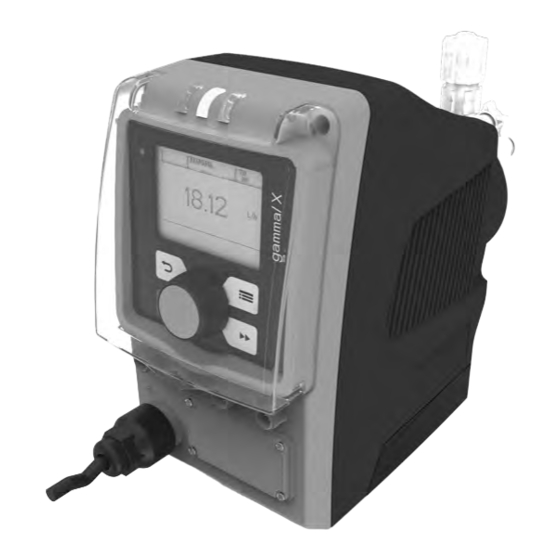
About this pump About this pump P_G_0063_SW Fig. 2: Overview of equipment, complete Control unit Drive unit Liquid end The pump is a microprocessor-controlled solenoid metering pump with the following features: Adjustment of the metering rate directly in l/h. Available material combinations: PP, PVDF, clear acrylic, PTFE and stainless steel. -
Page 7: Identity Code
Identity code Identity code Product identification This identity code serves to identify the product. Use the identity code from the Product Catalogue for orders. Product range gamma/ X GMXa Type - - - - Performance data and type - see nameplate Dosing head material Polypropylene Clear acrylic... - Page 8 Identity code Product range gamma/ X Logo 0 with ProMinent logo Electrical connection U 100-230 V ± 10%, 50/60 Hz Cable and plug A 2 m European B 2 m Swiss C 2 m Australian D 2 m USA / 115 V...
- Page 9 Identity code Product range gamma/ X 0 Dynamic metering monitor Remote stop / Remote control 0 without Bluetooth B with Bluetooth Language Deutsch English Spanish French DosingPump.ir...
-
Page 10: Safety Chapter
Do not open the unit! We would advise that the unit may only be opened by qualified personnel author‐ ised by ProMinent to avoid damage to the unit and guarantee the seamless and safe operation of the unit. All warranty claims will be invalidated if the unit is opened by unauthorised persons. -
Page 11: Intended Use
Observe the general limitations with regard to viscosity limits, chemical resistance and density - see also the ProMinent Resistance List in the Product Catalogue or at www.promi‐ nent.com. - Page 12 Safety chapter WARNING! Danger of electric shock Supply voltage may be present inside the pump housing. – Safely and quickly disconnect the pump from the mains/power supply if the pump housing has been damaged. Only return the pump to operation after an authorised repair.
- Page 13 – Take into account the resistance of the wetted materials and the ProMinent Resistance List when selecting the feed chemical - see the ProMinent Product Catalogue or visit ProMi‐ nent.
-
Page 14: Information In The Event Of An Emergency
Safety chapter Only the ProMinent service department is authorised to open the housing and hood (housing the control elements). Sound pressure level Sound pressure level LpA < 70 dB according to EN ISO 20361 at maximum stroke length, maximum stroke rate, maximum back pressure (water) 3.4 Information in the event of an emergency... - Page 15 Service The Service department refers to service technicians, who have received proven training and have been authorised by ProMinent to work on the system. DosingPump.ir...
-
Page 16: Storage, Transport And Unpacking
Storage, Transport and Unpacking Storage, Transport and Unpacking Safety Information WARNING! Only return metering pumps for repair in a cleaned state and with a flushed liquid end - refer to "Decommissioning! Only return metering pumps with a completed Decontamination Declaration form. The Decon‐ tamination Declaration constitutes an integral part of an inspection / repair order. -
Page 17: Overview Of Equipment And Control Elements
Overview of equipment and control elements Overview of equipment and control elements 5.1 Overview of equipment P_G_0063_SW Fig. 3: Overview of equipment, complete Control unit Drive unit Liquid end P_G_0053_SW Fig. 4: A. Liquid end with PV bleed valve; B. Liquid end with NP bleed valve; C. Self-bleeding liquid end (SEK) Discharge valve Bypass hose sleeve... -
Page 18: Control Elements
Overview of equipment and control elements 5.2 Control elements Control elements, overview P_G_0051_SW Fig. 5: Control elements LCD screen [Menu] key Clickwheel [Priming] key [STOP/START] key [Back] key Fault indicator (red) Warning indicator (yellow) Operating indicator (green) 10 "Diaphragm rupture indicator"... - Page 19 Overview of equipment and control elements Pressure display, identifier and fault displays on the LCD screen CONTACT memory open 12.0 12.0 12000 B0778 Fig. 6: Construction of the continuous display DosingPump.ir...
- Page 20 Overview of equipment and control elements Status bar Continuous display, central area Secondary display Refer to the chapter entitled "Main displays and secondary dis‐ plays" in the Appendix for the different main displays and secon‐ dary displays. The LCD screen supports the operation and adjustment of the pump using different information and various identifiers: CONTACT ANALOGUE...
- Page 21 Overview of equipment and control elements Identifier Meaning The pump was stopped by an error. Only with cyclical batch metering: the pump is waiting for the next cycle. ‘Access protection’ : the pump software is locked. Only with ‘AUX’ The pump is currently pumping at auxiliary capacity and/or auxiliary frequency. ‘memory’...
-
Page 22: Key Functions
Overview of equipment and control elements Identifier Meaning A "Flow Control" metering monitor is connected. A diaphragm rupture indicator is connected. The pump has created a log about the operation. ‘Menu’ (Set up). The pump is in the Further explanations can be found in the "Trouble‐ shooting"... - Page 23 Overview of equipment and control elements Refer to the "Set-up basics" chapter for information on how to adjust figures DosingPump.ir...
-
Page 24: Functional Description
Functional description Functional description 6.1 Liquid End The dosing process is performed as follows: The diaphragm is pressed into the dosing head; the pressure in the dosing head closes the suction valve and the feed chemical flows through the discharge valve out of the dosing head. The diaphragm is now drawn out of the dosing head;... - Page 25 Functional description P_G_0125_SW Fig. 8: Discharge stroke metering profiles with stroke L and time t (suction stroke shown as a dotted line) It is possible to selectively also slow the suction stroke with all these metering profiles for the discharge stroke - see . In this way, it is possible to prevent the main cause of inaccurate metering with high viscosity feed chemicals, namely the incomplete filling of the liquid end.
-
Page 26: Capacity
Functional description Oscillations in the back pressure in the metering line, which could lead to undesirable variations in the metering volume, are automat‐ ically compensated for by the power end/drive. This results in dosing precision, which otherwise could only be achieved with complex control circuits. -
Page 27: Functions
Functional description "Batch" operating mode This operating mode provides the option of working with large transfer factors (up to 99,999). Metering can be triggered either by [Clickwheel] or by a pulse received via the "External pressing the control" terminal by a contact or a semiconductor switching ele‐ ment. -
Page 28: Relays (Options)
Functional description "Stop" function The pump can be stopped without disconnecting it from the mains/ [STOP/START] . power supply by pressing [Priming] . "Priming" function Priming can be triggered by pressing 6.7 Relays (options) The pump has several connecting options available: "Fault indicating relay"... -
Page 29: Hierarchy Of Operating Modes, Functions And Fault Statuses
Functional description 6.9 Hierarchy of operating modes, functions and fault statuses The different operating modes, functions and fault statuses have a different impact on whether and how the pump reacts. The following list shows the order: 1. - Priming 2. - Stop 3. -
Page 30: Assembly
Assembly Assembly Please refer to the online version of the operating instructions on our website for the right dimen‐ sional drawings for the pump and mounting plate. Compare the dimensions on the dimensional drawing with those of the pump and/or mounting plate. - Page 31 Assembly P_G_0064_SW Fig. 10 Tab. 3: Suggested bolts and washers for fixing the assembly foot Bolt Type Size Washer DELTA-PT bolt 50 (WN5412/5452) A5.3 (DIN 125) PT bolt 50 (WN1441/1411 KA/B) Flat-head bolt M5 (DIN EN ISO 7045) A5.3 (DIN 125) Allen bolt/ M5 (DIN EN ISO 4762) A5.3 (DIN 125)
-
Page 32: Installation, Hydraulic
– Take into account the resistance of the wetted materials and the ProMinent Resistance List when selecting the feed chemical - see the ProMinent Product Catalogue or visit ProMi‐ nent. -
Page 33: Installing Hose Lines
Installation, hydraulic 8.1 Installing hose lines 8.1.1 Installation with metering pumps without degassing Safety information CAUTION! Warning of feed chemical spraying around The pipes can become loose or rupture if they are not installed correctly. – Route all hose lines so they are free from mechanical stresses and kinks. - Page 34 Installation, hydraulic CAUTION! Uncontrolled flow of feed chemical The feed chemical can leak through the metering pump in an uncontrolled manner in the event of excessive priming pressure. – Do not exceed the maximum permissible pri‐ ming pressure for the metering pump. INFORMATION: Align the pipes so that the metering pump and the liquid end can simply be removed from the side if necessary.
-
Page 35: Installation With Metering Pumps With Degassing
Installation, hydraulic Tighten the union nut (2). Pipe Union nut Rear clamp ring Front clamp ring Valve P_G_0067_SW Fig. 12: SS designs with pipe Installing hose lines - SS version CAUTION! Warning of feed chemical spraying around Connections can come loose in the event that hose lines are installed incorrectly on stainless steel valves. -
Page 36: Installation With Metering Pumps With Self-Degassing (Sek Type)
Installation, hydraulic 8.1.3 Installation with metering pumps with self-degassing (SEK type) Safety information CAUTION! – All the installation and safety information for metering pumps without self-degassing also apply. – Do not exceed the maximum values for priming lift, priming pressure and viscosity of the feed chemical. -
Page 37: Basic Installation Notes
Installation, hydraulic P_MAZ_0023_SW Fig. 14: SEK liquid end Anti-kink device Vent valve for the return line into the supply tank, 6/4 mm Red sleeve Discharge valve for the pressure line to the injection point, 6/4 - 12/9 mm Suction valve for the suction line in the supply tank, 6/4 - 12/9 8.2 Basic installation notes Safety notes CAUTION! - Page 38 Installation, hydraulic P_MAZ_0001_SW Fig. 15: Standard installation Main line Storage tank Legend for hydraulic diagram Symbol Explanation Symbol Explanation Metering pump Foot valve with filter meshes Injection valve Level switch Multifunctional valve Manometer DosingPump.ir...
-
Page 39: Installation, Electrical
Installation, electrical Installation, electrical WARNING! Danger of electric shock A mains voltage may exist inside the device. – Before any work, disconnect the device's mains cable from the mains. WARNING! Risk of electric shock In the event of an electrical accident, the pump must be quickly disconnected from the mains. -
Page 40: Supply Voltage Connector - Power Supply
Installation, electrical CAUTION! Material damage possible due to power surges Should the pump be connected to the mains power supply in parallel to inductive consumers (such as solenoid valves, motors), inductive power surges can damage the control when it is switched off. –... -
Page 41: Hmi Operating Unit
Installation, electrical 9.2 HMI operating unit Connect the HMI to the CAN socket above the LEDs of the pump base if the pump is operated with HMI. If the pump is operated without HMI, then plug the sealing cap sup‐ plied into the CAN socket above the LEDs of the pump base. - Page 42 Installation, electrical Electrical interface for pin 1 "Pause" - pin 2 "External contact" - pin 5 "Auxiliary capacity / Auxiliary frequency" Data Value Unit Voltage with open contacts Input resistance 10 kΩ Max. pulse frequency 25 pulse/s Min. pulse duration 20 ms P_BE_0014_SW Fig.
-
Page 43: Level Switch" Terminal
Installation, electrical "External contact" operating mode The pump performs one or more strokes if: Pin 2 and pin 4 are connected to each other for at least 20 ms. At the same time, pin 1 and pin 4 must also be connected to each other. -
Page 44: Diaphragm Rupture Indicator" Terminal
Installation, electrical Data Value Unit Voltage with open contacts Input resistance 10 kΩ Control via: potential-free contact (load: 0.5 mA at 5 V) or P_DE_0009_SW Fig. 20: Assignment on the pump Function 4-wire cable Power supply (5 V) brown Coding white Feedback blue... -
Page 45: Relays
Installation, electrical 9.3.5 Relays 9.3.5.1 Relay functions Tab. 4: gamma/ X GMXa Identity code Designation Type Maximum Maximum cur‐ Operational life‐ voltage rent time Min. switching operations no relay Fault indicating Changeover 230 V AC 50 000 relay, N/C contact Fault indicating 24 V DC 50 000... - Page 46 Installation, electrical ** only use ‘Relay 2’ for this relay type (semiconductor relay). ‘Relay 1’ for this relay type. *** only use Relay polarity You can set here how a relay is to switch. Menu setting Effect Break contact N/C The relay is closed in normal mode and opens with a triggering event.
- Page 47 Installation, electrical The fault indicating/pacing relay can be retrofitted and is opera‐ tional once attached to the relay board - refer to the "Retrofitting relays" supplementary instructions. Electrical interface for semiconductor switch pacing relay: Data Value Unit P_SI_0044 Max. residual voltage at I = 1 µA 0.4 V off max...
- Page 48 Installation, electrical Identity code c To pin VDE cable Contact Relay yellow "+" Current output Green “-" Current output P_G_0073_SW white N/C (normally closed) Relay Fig. 29: Assignment on the pump N/O (normally open) brown C (common) Relay DosingPump.ir...
-
Page 49: Basic Set-Up Principles
Basic set-up principles Basic set-up principles Please also refer to all the overviews covering – "Operating/set-up overview" and "Operating menu for gamma/ X, complete" in the appendix and the "Overview of equipment and control elements" and "Control elements” chapters. The pump exits the menu and returns to a con‐ –... - Page 50 Basic set-up principles [] Menu. To complete the setting: press ‘Menu’ via the Alternatively: wait 60 seconds or exit the [Menu] key or using ‘End’ . Confirming an entry [Clickwheel] . Briefly press the ð The software switches to the next menu point or back to the menu and saves the entry.
-
Page 51: Checking Adjustable Variables
Basic set-up principles To run through the figures again, if necessary (possibly because of an incorrect figure), when you get to the last [Priming] again - see above Figure, point c). figure press ð Now you can start from the beginning again. Confirming adjustable variables [Clickwheel] 1x. -
Page 52: Set Up / 'Menu
‘Menu’ Set up / ‘Menu’ Set up / Refer to the overviews covering "Operating/set – up overview" and "Operating menu gamma/ X, complete" in the appendix and in the "Overview of equipment" - "Control elements" chapters by way of supplementary information. The pump exits the menu and returns to a con‐... -
Page 53: Operating Mode
‘Menu’ Set up / ‘Operating mode’ 11.2.1 ‘Menu / Information è Settings è Operating mode è ...’ ‘Manual’ 11.2.1.1 ‘Menu / Information è Settings è Operating mode Manual’ è ‘Manual’ operating mode lets you operate the pump manually. The capacity and/or stroke rate and stroke length can be set in the continuous displays in this operating mode. - Page 54 ‘Menu’ Set up / ‘Automatic’ ‘Off’ ) factor The number of strokes per pulse depends on the factor which you can input. By using a factor you can multiply incoming pulses by a factor between 1.01 to 99.99 or reduce them by a factor of 0.01 to 0.99: Number of strokes executed = factor x number of incoming pulses...
- Page 55 ‘Menu’ Set up / If a remainder is obtained when dividing by the factor, then the unit adds the remainders together. As soon as this sum reaches or exceeds "1", the pump executes an additional stroke. Therefore on average during the metering operation, the resul‐ tant number of strokes precisely matches the factor.
- Page 56 ‘Menu’ Set up / CAUTION! – The pump maintains its stroke rate when ‘Manual’ operating mode changing over from ‘Batch’ operating mode. [STOP/START] or the – When you press ‘Memory’ is "Pause" function is activated, the cleared. In operation, the batch size can be changed more easily by using the "Batch size"...
- Page 57 ‘Menu’ Set up / I [mA] B0088 Fig. 33: Frequency-current diagram for "Linear curve" Plot a diagram similar to the one above – with values for (I1, F1) and (I2, F2) – so that you can set the pump as desired! The smallest processable difference between I1 and I2 is 4 mA (ll I1-I2 ll ≥4 mA).
-
Page 58: Automatic
‘Menu’ Set up / Using this processing type, you can control a metering pump using the current signal as shown in the diagram above. ‘Lower side band’ type of Everything functions according to the processing. ‘Automatic’ 11.2.2 ‘Menu / Information è Settings è Automatic è ...’ ‘Automatic’... -
Page 59: Metering
‘Menu’ Set up / 11.2.4 Metering ‘Menu / Information è Settings è Metering è ...’ ‘Discharge stroke’ 11.2.4.1 ‘Menu / Information è Settings è Metering Discharge stroke è ...’ è In the ‘Settings’ - ‘Discharge stroke’ sub-menu, you can precisely match the pump metering flow over time to the requirements of the particular application. - Page 60 ‘Menu’ Set up / P_G_0125_SW Fig. 35: Discharge stroke metering profiles with stroke L and time t (suction stroke shown as a dotted line) ‘Suction stroke’ 11.2.4.2 ‘Menu / Information è Settings è Metering Suction stroke è ...’ è It is possible to selectively also slow the suction stroke with all these metering profiles for the discharge stroke - see .
- Page 61 ‘Menu’ Set up / P_G_0075_SW normal Fig. 36: Suction stroke metering profiles with stroke L and time t Normal Normal suction stroke Suction stroke for viscous feed chemical Suction stroke for average viscosity feed chemical Suction stroke for high-viscosity feed chemical –...
- Page 62 ‘Menu’ Set up / Pressure rating / Size of liquid 2504 1009 Switch-off pressure Switch-off pressure: Pressure above which the unit is switched off for the medium term in the event of excess pressure = Pressure rating plus 10 ... 20%. ‘Monitoring’...
-
Page 63: Concentration
‘Menu’ Set up / 11.2.4.4.3 Message with overpressure You can have the pump output a message in the event of over‐ ‘Message with overpressure’ pressure using the programmable function. 11.2.4.4.4 Message when no pressure You can have the pump output a message in the event of no pres‐ ‘Message when no pressure’... - Page 64 ‘Menu’ Set up / The "Concentration" continuous display only – appears, if: the pump is calibrated. – the ‘Concentration’ menu was run through – in the operating mode used. and ‘Concentration control’ was switched – to ‘active’ - in the operating mode being used.
- Page 65 ‘Menu’ Set up / Procedure CAUTION! The precision of the concentration is strongly dependent on: – the precision of the metering pump calibration. – the precision of the inputs. Calibrate the metering pump if it is not yet calibrated - see ‘Settings’...
- Page 66 ‘Menu’ Set up / CAUTION! Danger of too high concentrations The metering pump can continue to meter if the flow falls or stops entirely. – Take system-based precautions to prevent the metering pump from continuing to meter in these circumstances. The prerequisites are that: the flowing medium has the same density as water (1 kg/l ≜...
- Page 67 ‘Menu’ Set up / Tab. 12: Possible values of adjustable variables Adjustable variable Lower value Upper value Increment Contact gap in l/contact 000.10 999.99 000.01 Mass concentration in % 000.01 100.00 000.01 Mass density in kg/l 0.50 2.00 0.01 ‘Batch’ operating mode (settings for the ‘Concentration’ function) 11.2.5.3 ‘Menu / Information è...
- Page 68 ‘Menu’ Set up / [Menu] Press ð A continuous display appears. [Clickwheel] to go to the "Concentration" contin‐ Press the uous display (ppm or %). You can enter the desired mass concentration using the [Clickwheel] . Tab. 13: Possible values of adjustable variables Adjustable variable Lower value Upper value...
- Page 69 ‘Menu’ Set up / Calibrate the metering pump if it is not yet calibrated - see ‘Settings’ - ‘Calibration’ chapter. chapter ‘Automatic’ - ‘on’ Check whether the metering pump is set to metering mode. ‘Analogue’ operating mode and confirm with the Select [Clickwheel] .
-
Page 70: Calibrate
‘Menu’ Set up / Tab. 14: Possible values of adjustable variables Adjustable variable Lower value Upper value Increment 0000.1 9999.9 0000.1 Max. flow in m Mass concentration in % 000.01 100.00 000.01 Mass density in kg/l 0.50 2.00 0.01 11.2.6 Calibrate ‘Menu / Information è... -
Page 71: System
‘Menu’ Set up / P_G_0071_SW [Clickwheel] to scroll through the continuous displays Preparation Use the to check whether litres or gallons have been selected. If the incorrect volume unit has been selected, correct it in ‘Menu / Information è Settings è System Volume unit’... - Page 72 ‘Menu’ Set up / ‘System’ menu splits into the following sub-menus: ‘Dosing head’ ‘Volume unit’ ‘Pressure unit’ ‘Pressure adjustment’ ‘Start behaviour’ ‘Dosing head ’ 11.2.7.1 ‘Menu / Information è Settings è System è Dosing head ...’ è CAUTION! – Should a different liquid end size be fitted, then the pump must be reprogrammed in the ‘Dosing head’...
-
Page 73: Inputs/Outputs
‘Menu’ Set up / There is no ‘Pressure adjustment’ sub-menu with pumps with SER dosing heads. Requirements: A manometer is installed in the discharge line. Everything is set on the pump. ‘Pressure adjustment’ sub-menu. Shift to the ð The ‘Start pump’ menu item appears. [Clickwheel] to confirm ‘Yes’... - Page 74 ‘Menu’ Set up / ‘Inputs/outputs’ menu is split into the following sub-menus: ‘Auxiliary capacity’ / ‘Auxiliary frequency’ ‘Relay1’ (optional) ‘Relay2’ (optional) ‘Flow monitor’ (only if connected) ‘Diaphragm rupture’ (only if connected) ‘Pause input’ (optional) ‘Niveau monitoring’ ‘Auxiliary capacity’ / ‘Auxiliary frequency’ 11.2.8.1 ‘Menu / Information è...
- Page 75 ‘Menu’ Set up / Menu setting Effect Timer The relay switches when requested by the timer. Error The relay switches in the event of a fault message (red LED*). Warning The relay switches in the event of a warning message (yellow LED*). Warning + error The relay switches in the event of a warning message (yellow LED*) or a fault message (red LED*).
- Page 76 ‘Menu’ Set up / 11.2.8.4 mA output ‘Menu / Information è Settings è Inputs/outputs mA-Output è ...’ è You can enter here which signal is to be output similar to the pump capacity and as an mA signal and how the pump is to respond. The following can be selected one after the other - Table display: ‘mA-Output’...
- Page 77 ‘Menu’ Set up / The setting options for the ‘Flow control’ function are only available if a flow control is electrically installed. The symbol for flow control appears: A metering monitor, such as a Flow Control (also DulcoFlow ), can ®...
- Page 78 11.2.8.8.2 Continuous Calibrate The ProMinent suction lance with continuous level measurement can measure the liquid level in a 30-litre canister with 5 % preci‐ sion. The relevant secondary display of the gamma/ X indicates the liquid level, or the liquid level can be reported to the control panel by bus.
-
Page 79: Bleeding
(retrofittable), the pump can be bled via a bleed relay. There are 2 hardware options for automatically bleeding the dis‐ charge side: via ProMinent's bleed module in the liquid end. via a customer implemented bleed facility in the discharge line. The relay - "Relay” – "with automatic bleed" - changes its switching status for the period during which the pump is priming. -
Page 80: Priming Time
‘Menu’ Set up / Detailed explanation: ‘Off’ has been selected in the menu, this function is deacti‐ 1 - If vated. ‘Periodic’ was selected in the menu, then the control unit 2 - If periodically triggers the bleed procedure with an adjustable ‘cycle’... -
Page 81: Set Time
‘Menu’ Set up / In the ‘Priming time’ menu, you can select how long the metering [Priming] has been pressed. pump is to prime once In operation, the stroke length can be changed more easily using the "Priming time" display: Press [Priming] - the pump starts to prime. -
Page 82: Activation / Deactivation
‘Menu’ Set up / stop / start the pump ‘Batch (time)’ ) trigger a batch ( 11.3.1 Activation / deactivation ‘Menu / Information è Timer è Activation è ...’ You can only program the timer when ‘Activation’ is set to ‘inactive’ . ‘Activation’... - Page 83 ‘Menu’ Set up / The following administration functions are available to manage the commands (program lines): ‘New’ ) 1 - Reprogram program line ( ‘Show’ ) 2 - Check program line ( ‘Change’ ) 3 - Change program line ( ‘Clear’...
- Page 84 ‘Menu’ Set up / Time event (trigger) Action Workdays 1 Time of day Manual 20.00 l/h (Mo-Fr) 12:00 This corresponds to the following instruction: WHEN triggering event, THEN action The time event (trigger) defines what action or at what time an action is to take place.
- Page 85 ‘Menu’ Set up / Action Description Value ‘Relay1 **’ Have the relay switch to status ... open closed ‘Relay2 **’ Have the relay switch to status ... open closed ‘Contact’ Switch over in this operating mode ‘Batch (input)’ Switch over in this operating mode ‘Analogue’...
- Page 86 ‘Menu’ Set up / The switching time specifies when the action is to take place. Example Time events (triggers) Action Cycle Switching time Workdays 1 (Mo-Fr) Time of day 12:00 Manual Tab. 19: Cyclic time events Cycle Time ‘hourly’ hourly at mm. Minute ‘daily’...
- Page 87 ‘Menu’ Set up / For details on the sorting sequence of the pro‐ – gram lines see Ä ‘Sorting sequence’ on page 87. The timer program can have a maximum of 99 – program lines. ‘Show’ ) 11.3.2.3 Check program lines ( ‘Menu / Information è...
-
Page 88: Clear All
‘Menu’ Set up / ‘Change’ ) 11.3.2.4 Change program lines ( ‘Menu / Information è Timer è Set timer è Change’ [Clickwheel] to select the required program line / Use the instruction according to its number and press the [Clickwheel] . Click through the instruction and change it. - Page 89 ‘Menu’ Set up / Task: Example of "Weekday metering" The pump is to meter 2 litres every half hour every weekday (Mon-Fri) between 8:00 and 11:00. Solution: As you define switching times with the timer, you need to first define the switching points at 08:30, 09:30 and 10:30. To meter 2 litres, the pump needs to work in ‘Manual’...
-
Page 90: Timer Information
‘Menu’ Set up / Test your programming! The secondary display “Timer” can help with this as it shows the next instruction and the remaining time. (To [Clickwheel] in a access this secondary display, press the continuous display until a long series of small circles [Clickwheel] to navi‐... -
Page 91: Brief Explanation Of Selected Functions
‘Menu’ Set up / Problem Possible cause of fault Remedy ‘Init’ instruction with The pump starts pumping unex‐ The timer clears every “Manual” Enter an ‘Halt’ action. pectedly. stop when activated - see “Timer behaviour on start” The timer does not react to a Config I/O was not configured as Configure Config I/O as “Config contact signal at the corre‐... -
Page 92: Service
‘Menu’ Set up / Inputs Pins 1 - 3 of the "Config I/O” socket can be inputs and outputs. That can be programmed. Delayer Delayers are started event- or time-controlled. On expiry of the delay time, the delayer itself can trigger any actions. ‘Service’... -
Page 93: Password
‘Menu’ Set up / ‘Password ’ 11.4.2 ‘Menu / Information è Service è Password è ...’ ‘Change You can enter a password of your choice in the password’ menu. ‘Clear counters’ 11.4.3 ‘Menu / Information è Service è Clear counters è ...’ You can reset the counters to "0"... -
Page 94: Diaphragm Replacement
‘Menu’ Set up / Line Information Switching-on duration, stroke rate since switching Room temperature, status information on the error (for developers) ‘Diaphragm replacement’ 11.4.5 ‘Menu / Information è Service è Diaphragm replacement ...’ è You can move the slide rod into the "replacement position" here ‘To change position’... -
Page 95: Language
‘Menu’ Set up / ‘Language’ 11.5 ‘Menu / Information è Language è ...’ ‘Language’ You can select the desired operating language in the menu. DosingPump.ir... -
Page 96: Operation
Operation Operation WARNING! Fire hazard with flammable media Only with combustible media: These may start to burn when combined with oxygen. – During filling and draining of the liquid end, an expert must ensure that feed chemical does not come into contact with oxygen. This chapter describes all the operating options in a continuous display (several symbols and the pressure display appear at the top in the black bar) for the trained person at the pump. - Page 97 Operation Ä ‘Set Up Overview of If the "lock" - "lock all" has been set - see the gamma/ X’ on page 97 , first enter the ‘Password’ after [Clickwheel] . pressing the List of directly changeable variables: Capacity Stroke rate Stroke length Factor Contact volume...
-
Page 98: Maintenance
Maintenance Maintenance WARNING! It is mandatory that you read the safety information and specifications in the "Storage, Transport and Unpacking" chapter prior to shipping the pump. WARNING! Fire hazard with flammable media Only with flammable media: They can be ignited by oxygen. - Page 99 Maintenance P_G_0054_SW Fig. 39: The leakage hole Interval Maintenance work Personnel Annually* Check the diaphragm for damage - refer to "Repair". Technical personnel * with normal loading (approx. 30% of continuous operation). With heavy-duty loading (e.g. continuous operation): Shorter inter‐ vals.
-
Page 100: Repair
Repair Repair Safety information User qualification, mechanical repair: trained and qualified per‐ sonnel. User qualification, electrical repair: Electrical technician. WARNING! Contact with the feed chemical Wetted parts are exposed and touched during repair work. – Protect yourself against the feed chemical if it is hazardous. -
Page 101: Replacing The Diaphragm
Repair 14.1 Replacing the diaphragm INFORMATION: The order no. (part number) of the appropriate diaphragm or the spare parts kit can be found at the end of the ‘Service’ menu. Put in place protective measures, if necessary. Adhere to the material safety data sheet for the feed chemical. Prevent the escape of feed chemical. - Page 102 Repair Tentatively screw the new diaphragm (3) onto the drive axle as far as the stop - ensure that this is successful, otherwise the pump will not subsequently meter precisely. Unscrew the diaphragm (3) again. Place the backplate (4) onto the pump housing (6). Make sure that the leakage hole points downwards when the pump is subsequently fitted - see figure in the "Main‐...
-
Page 103: Replacing The Vptfe Diaphragm
Repair 14.1.1 Replacing the vPTFE diaphragm Spare parts for the vPTFE diaphragm The vPTFE diaphragm (full PTFE diaphragm) is replaced in the same way as the standard diaphragm. A fitted vPTFE diaphragm needs to be replaced once the dosing head screws have been loosened, as the pump will otherwise no longer be tight. -
Page 104: Cleaning Valves
Repair Thoroughly dry the diaphragm rupture indicator. ð The continuous display no longer indicates a diaphragm rupture. Screw the clean and dry diaphragm rupture indicator into the hole until hand-tight and liquid-tight - without using tools. 14.3 Cleaning valves INFORMATION: Refer to the exploded drawings of the pump when working on the unit. -
Page 105: Troubleshooting
Troubleshooting Troubleshooting Safety information WARNING! Warning of hazardous feed chemical Should a dangerous feed chemical be used: it may escape from the hydraulic components when working on the pump, material failure or incorrect handling of the pump. – Take appropriate protective measures before working on the pump (e.g. -
Page 106: Faults With Error Message
Fault description Cause Remedy Personnel No. 0: The identifier appears System or EPRom error Return the pump to ProMinent. followed by the message ‘System error’ . ‘Analog’ The pump is in Eliminate the cause of the low Technical No. 1: The identifier i >... - Page 107 No. 8: No identifier appears but Pump restart, initialisations Pump restart. ‘Initialisation’ the message incomplete. appears. The solenoid is not con‐ Return the pump to ProMinent. No. 9: The identifier appears followed by the message nected. ‘Solenoid not connected’ . No. 10: The identifier appears An incorrect parameter has Correct the parameter.
-
Page 108: Warning Messages On The Lcd Screen
No. 20: The identifier and the ‘Module missing’ missing. personnel message appear. Communication between Return the pump to ProMinent. the optional module and pump electronics is not working. The bus contact between Rectify the cause (cable, con‐ Technical No. 21: The identifier and the ‘Module... -
Page 109: All Other Faults
‘Cavitation’ . 15.2.3 All other faults Please contact the responsible ProMinent branch or representa‐ tive! 15.3 Log book 15.3.1 Fault messages in the log book For more information on the ‘ERROR’ messages - refer to the chapter "Fault messages on the LCD... -
Page 110: Warning Messages In The Log Book
The pump has detected too low a back pressure. No connection between the optional module and the bus. An optional module is no longer found. * Please get in touch with the ProMinent head office should this fault occur. 15.3.2 Warning messages in the log book For more information on the ‘WARNING’... -
Page 111: Event Messages In The Log Book
Troubleshooting 15.3.3 Event messages in the log book Tab. 24: Events Log book no. Description Head change is active – dongle was inserted. Parameter menu called up – dongle was inserted. Air gap measured – dongle was inserted. Too high current was detected but no fault message generated. The controller data was not plausible. - Page 112 Troubleshooting Tab. 25: Information on the detailed view Line Information Date/time Type of entry (fault, warning ...) Total operating time, total number of strokes Switching-on duration, stroke rate since switching Room temperature, status information on the error (for developers) DosingPump.ir...
-
Page 113: Decommissioning And Disposal
Decommissioning and disposal Decommissioning and disposal Decommissioning WARNING! Danger from chemical residue There is normally chemical residue in the liquid end and on the housing after operation. This chemical residue could be hazardous to people. – It is essential that the safety information in the "Storage, transport and unpacking"... - Page 114 Decommissioning and disposal Disposal WARNING! Eye injury from compression spring A compression spring is fitted in the pump in the drive magnet, which could cause eye injuries when opened. – Do not dismantle the pump when disposing of it or put in place appropriate protective meas‐ ures.
-
Page 115: Technical Data
Technical data Technical data 17.1 Performance data Tab. 26: At 200 strokes/minute and 100% stroke length Type Pump capacity Connector Priming Max. priming Suction lift size pressure on lift the suction outer Æ x side 5, 6 inner Æ ml/stroke m water m water column... -
Page 116: Performance Data With Vptfe Diaphragm
Technical data Type Pump capacity Connector Priming Max. priming Suction lift size pressure on lift the suction outer Æ x side 5, 6 inner Æ ml/stroke m water m water column column 1009 0.67 0715 13.5 1.12 0424 20.0 1.67 12x9 The pressure on the discharge side needs to be at least 1.5 bar higher than the pressure on the suction side. -
Page 117: Accuracy
Technical data Type Minimum pump capacity * Connector Suction Priming Max. pri‐ size lift** lift*** ming pres‐ ... PVT at maximum back pressure sure on the outer Æ x suction inner Æ side ml/stroke m water m water mbar column column 0708 ... -
Page 118: Viscosity
Technical data 17.3 Viscosity Tab. 28: The liquid ends are suitable for the following viscosity ranges: Design Viscosity in mPas Standard 0 ... 200 With valve springs 201 ... 500 With HV head 501 ... 3000* Self-degassing (SEK) 0 ... 50 * Even significantly higher with correctly adjusted installation. -
Page 119: Electrical Data
Technical data Drive unit Housing parts: Polyphenylene ether (PPE with fibreglass) 17.5 Electrical data Design: 100 ... 230 V ±10%, 50/60 Hz, gamma/ X GMXa Parameter Nominal power**, approx. 25 W 30 W Current I eff 0.25 ... 0.10 A 0.30 ... -
Page 120: Climate
Technical data 17.7 Climate Data Value Unit Maximum air humidity*: 95 % rela‐ tive humidity * Non-condensing Test: Humid heat, cyclical, in accordance with EN 680068-2-30: 2005 17.8 Altitude of site Data Value Unit Altitude of site , max.: 2000 m above 17.9 Degree of protection and safety requirements 17.9.1... -
Page 121: Shipping Weight
Technical data Identical use of accessories, such as back pressure valves, multifunctional valves and flushing assembly Compatibility of resistance by the equivalence of the material used for the liquid ends Compatibility to the gamma/ L product range is not guaranteed for the following points: External dimensions of the pump Distance between the support surface for the mounting foot... -
Page 122: Exploded Drawings And Ordering Information
Exploded drawings and ordering information Exploded drawings and ordering information 18.1 Exploded drawings Liquid end gamma/ X 1602 - 1604 PP_2 P_G_0032_SW Fig. 41 Tab. 30: Spare parts for liquid end gamma/ X 1602 - 1604 PP_2 Pos. Description Connector kit Discharge valve Diaphragm Suction valve... - Page 123 Exploded drawings and ordering information Liquid end gamma/ X 0708 (1009) - 0220 (0424) PP_2 P_G_0033_SW Fig. 42 Tab. 31: Spare parts for liquid end gamma/ X 0708 (1009) - 0220 (0424) PP_2 Pos. Description Connector kit Discharge valve Diaphragm Suction valve Liquid end gamma/ X 0708 (1009) PPE2...
- Page 124 Exploded drawings and ordering information Liquid end gamma/ X 0245 PP_0 P_G_0034_SW Fig. 43 Tab. 32: Spare parts kit for liquid end gamma/ X 0245 PP_0 Pos. Description Connector kit Discharge valve Diaphragm Suction valve Liquid end gamma/ X 0245 PPE0 PPB0 PPT0...
- Page 125 Exploded drawings and ordering information Liquid end gamma/ X 1602 - 2504 NP_0 and NP_2 P_G_0035_SW Fig. 44 Tab. 33: Spare parts for liquid end gamma/ X 1602 - 2504 NP NP_0 and NP_2 Pos. Description Connector kit Discharge valve Diaphragm Suction valve Liquid end gamma/ X 2002...
- Page 126 Exploded drawings and ordering information Liquid end gamma/ X 1602 NPE_ NPB_ NPT_ Liquid end 1051073 1051071 1051087 with bleed valve_2 Liquid end 1051084 1051072 1051088 without bleed valve, _0 Spare parts kit 1001715 1001723 1023109 Diaphragm 1000246 1000246 1000246 Liquid end gamma/ X 2504 NPE_ NPB_...
- Page 127 Exploded drawings and ordering information Liquid end gamma/ X 0708 (1009) - 0220 (0424) NP_0 and NP_2 P_G_0036_SW Fig. 45 Tab. 34: Spare parts for liquid end gamma/ X 0708 (1009) - 0220 (0424) NP_0 and NP_2 Pos. Description Connector kit Discharge valve Diaphragm Suction valve...
- Page 128 Exploded drawings and ordering information Liquid end gamma/ X 0220 (0424) NPE_ NPB_ NPT_ Liquid end with 1050969 1050952 1050986 bleed valve, _2 Liquid end 1050975 1050958 1050992 without bleed valve, _0 Spare parts kit 1051118 1051107 1051129 Diaphragm 1045456 1045456 1045456 Liquid end gamma/ X 0245 NP_0 and...
- Page 129 Exploded drawings and ordering information Liquid end gamma/ X 1602 - 1604 PVT2 P_G_0038_SW Fig. 47 Tab. 36: Spare parts for liquid end gamma/ X 1602 - 1604 PVT2 Pos. Description Connector kit Discharge valve Diaphragm Suction valve Liquid end gamma/ X 1602 PVT2 Liquid end 1050994...
- Page 130 Exploded drawings and ordering information Liquid end gamma/ X 0708 (1009) - 0220 (0424) PVT2 P_G_0039_SW Fig. 48 Tab. 37: Spare parts kit for liquid end gamma/ X 0708 (1009) - 0220 (0424) PVT2 Pos. Description Connector kit Discharge valve Diaphragm Suction valve Liquid end gamma/ X 0708 (1009)
- Page 131 Exploded drawings and ordering information Liquid end gamma/ X 0245 PVT0 P_G_0034_SW Fig. 49 Tab. 38: Spare parts kit for liquid end gamma/ X 0245 PVT0 Pos. Description Connector kit Discharge valve Diaphragm Suction valve Liquid end gamma/ X 0245 PVT0 Liquid end 1050999...
- Page 132 Exploded drawings and ordering information Liquid end gamma/ X 1604 - 0220 (0424) PV_4 P_G_0049_SW Fig. 50 Tab. 39: Spare parts kit for liquid end gamma/ X 1604 - 0220 (0424) PV_4 Pos. Description Connector kit with hose nozzle Diaphragm Liquid end gamma/ X 1604 PV_4 Liquid end...
- Page 133 Exploded drawings and ordering information Liquid end gamma/ X 0220 (0424) PV_4 Liquid end 1051003 Spare parts kit 1051134 Diaphragm 1045456 Liquid end gamma/ X 1602 - 1604 TTT0 P_G_0041_SW Fig. 51 Tab. 40: Spare parts for liquid end gamma/ X 1602 - 1604 TTT0 Pos.
- Page 134 Exploded drawings and ordering information Liquid end gamma/ X 0708 (1009) - 0220 (0424) TTT0 P_G_0042_SW Fig. 52 Tab. 41: Liquid end gamma/ X 0708 (1009) - 0220 (0424) TTT0 Pos. Description Connector kit Discharge valve Diaphragm Suction valve Liquid end gamma/ X 0708 (1009) TTT0 Liquid end 1051018...
- Page 135 Exploded drawings and ordering information Liquid end gamma/ X 0245 TTT0 P_G_0043_SW Fig. 53 Tab. 42: Spare parts kit for liquid end gamma/ X 0245 TTT0 Pos. Description Connector kit Discharge valve Diaphragm Suction valve Liquid end gamma/ X 0245 TTT0 Liquid end 1051021...
- Page 136 Exploded drawings and ordering information Tab. 43: Spare parts for liquid end gamma/ X 1602 - 2504 SST0 Pos. Description Connector kit Discharge valve Diaphragm Suction valve Liquid end gamma/ X 1602 (2002) SST0 Liquid end 1051004 Spare parts kit 1001731 Diaphragm 1000246...
- Page 137 Exploded drawings and ordering information Liquid end gamma/ X 0414 (0715) SST0 Liquid end 1051007 Spare parts kit 1001734 Diaphragm 1000249 Liquid end gamma/ X 0220 (0424) SST0 Liquid end 1051008 Spare parts kit 1051139 Diaphragm 1045456 Liquid end gamma/ X 0245 SST0 P_G_0046_SW Fig.
- Page 138 Exploded drawings and ordering information Liquid end gamma/ X 1602 -2504 SER, self-bleeding without bypass, NPT7 P_G_0035_SW Fig. 57 Tab. 46: Spare parts for liquid end gamma/ X 1602 - 2504 SER, self-bleeding without bypass, NPT7 Pos. Description Connector kit Discharge valve Diaphragm Suction valve...
- Page 139 Exploded drawings and ordering information Liquid end gamma/ X 0708 (1009) - 0220 (0424) SER, self-bleeding without bypass, NPT7 P_G_0036_SW Fig. 58 Tab. 47: Spare parts for liquid end gamma/ X 0708 (1009) - 0220 (0424) SER, self-bleeding without bypass, NPT7 Pos.
- Page 140 Exploded drawings and ordering information Liquid end gamma/ X 1602 - 1604 SER, self-bleeding without bypass, PVT7 P_G_0038_SW Fig. 59 Tab. 48: Spare parts for liquid end gamma/ X 1602 - 1604 SER, self-bleeding without bypass, PVT7 Pos. Description Connector kit Discharge valve Diaphragm Suction valve...
- Page 141 Exploded drawings and ordering information Liquid end gamma/ X 0708 (1009) - 0220 (0424) SER, self-bleeding without bypass, PVT7 P_G_0039_SW Fig. 60 Tab. 49: Spare parts for liquid end gamma/ X 0708 (1009) - 0220 (0424) SER, self-bleeding without bypass, PVT7 Pos.
- Page 142 Exploded drawings and ordering information Liquid end gamma/ X 0220 (0424) PVT7 Liquid end SER, self-bleeding 1051104 without bypass Spare parts kit 1047837 Diaphragm 1045456 Liquid end gamma/ X 1602 - 1604 PP_9 and NP_9 P_G_0047_SW Fig. 61 Pos. Part 1, 9, 10 Connector kit Bleed valve...
- Page 143 Exploded drawings and ordering information Type Order No. 1602 1050926 1604 1050927 Tab. 51: Liquid ends Type Order No. NPE_9 1602 1050977 1604 1050978 NPB_9 1602 1050960 1604 1050961 Spare parts kits for Material version Order No. type: 1602 with spring 1001757 1604 with spring 1035335...
- Page 144 Exploded drawings and ordering information Liquid end gamma/ X 0708 (1008) - 0220 (0420) PP_9 and NP_9 P_G_0048_SW Fig. 62 Pos. Part 1, 9, 10 Connector kit Bleed valve Discharge valve Diaphragm Suction valve Tab. 52: Liquid ends Type Order No. PPE9 0708 / 1009 1050939...
- Page 145 Exploded drawings and ordering information Tab. 53: Liquid ends Type Order No. NPE9 0708 / 1009 1050979 0414 / 0715 1050980 0220 / 0424 1050981 NPB9 0708 / 1009 1050962 0414 / 0715 1050963 0220 / 0424 1050964 Spare parts kits for Material version Order No.
-
Page 146: Ordering Information
1061480 Retrofit kit for bleed valve 3-p. 1061481 230 V PVF: Further sources of information Further information on spare parts, accessories and options can be found in: the exploded drawings the identity code in www.prominent.com the ProMinent product catalogue DosingPump.ir... -
Page 147: Dimensional Drawings
Dimensional drawings Dimensional drawings Compare the dimensions on the dimensional – drawing with those of the pump and mounting foot. All dimensions are in mm. – Dimensional drawing of gamma/ X mounting foot P_G_0065_SW 40082099 Fig. 63 DosingPump.ir... - Page 148 Dimensional drawings Dimensional drawing gamma/ X, material versions PP_2 P_G_0055_SW 40129808 Fig. 64 gamma/ X M70 gamma/ X M85 1602 1604 0708 0414 0220 1009 0715 0424 0245 ØA C (with bleed valve) (without bleed valve) DosingPump.ir...
- Page 149 Dimensional drawings Dimensional drawing gamma/ X, material versions NP_2 P_G_0056_SW 40129858 Fig. 65 gamma/ X M70 gamma/ X M85 1602 1604 0708 0414 0220 2504 1009 0715 0424 0245 ØA C (with bleed valve) (without bleed valve) DosingPump.ir...
- Page 150 Dimensional drawings Dimensional drawing gamma/ X, material version PVT2 P_G_0057_SW 40129862 Fig. 66 gamma/ X M70 gamma/ X M85 1602 1604 0708 0414 0220 1009 0715 0424 0245 ØA C (with bleed valve) (without bleed valve) DosingPump.ir...
- Page 151 Dimensional drawings Dimensional drawing gamma/ X, material version PVT4 P_G_0060_SW 40129872 Fig. 67 gamma/ X M70 gamma/ X M85 1604 0708 0414 0220 1009 0715 0424 ØA DosingPump.ir...
- Page 152 Dimensional drawings Dimensional drawing gamma/ X, material version TTT0 P_G_0061_SW 40129872 Fig. 68 gamma/ X M70 gamma/ X M85 1602 1604 0708 0414 0220 1009 0715 0424 0245 ØA DosingPump.ir...
- Page 153 Dimensional drawings Dimensional drawing gamma/ X, material version SST0 P_G_0062_SW_2 40129874 Fig. 69 gamma/ X M70 gamma/ X M85 1602 1604 0708 0414 0220 2504 1009 0715 0424 0245 2002 ØA 15.8 207.3 ISO - Rp 3/8 DosingPump.ir...
- Page 154 Dimensional drawings Dimensional drawing gamma/ X, material version PPB9 P_G_0058_SW 40129864 Fig. 70 gamma/ X M70 gamma/ X M85 1602 1604 0708 0414 0220 1009 0715 0424 ØA DosingPump.ir...
- Page 155 Dimensional drawings Dimensional drawing gamma/ X, material version NPB9 P_G_0059_SW 40129871 Fig. 71 gamma/ X M70 gamma/ X M85 1602 1604 0708 0414 0220 1009 0715 0424 ØA DosingPump.ir...
-
Page 156: Diagrams For Setting The Capacity
Diagrams for Setting the Capacity Diagrams for Setting the Capacity GMXa 1602 GMXa 1604 C [l/h] f [%] C [l/h] f [%] 200 1/min 200 1/min 180 1/min 180 1/min 160 1/min 160 1/min 140 1/min 140 1/min 120 1/min 120 1/min 100 1/min 100 1/min... - Page 157 Diagrams for Setting the Capacity GMXa 2504 GMXa 0220 C [l/h] f [%] C [l/h] f [%] 200 1/min 200 1/min 180 1/min 180 1/min 160 1/min 160 1/min 140 1/min 140 1/min 120 1/min 120 1/min 100 1/min 100 1/min 80 1/min 80 1/min 60 1/min...
- Page 158 Diagrams for Setting the Capacity GMXa 0424 GMXa 0245 C [l/h] f [%] C [l/h] f [%] 200 1/min 200 1/min 180 1/min 180 1/min 160 1/min 160 1/min 140 1/min 140 1/min 120 1/min 120 1/min 100 1/min 100 1/min 80 1/min 80 1/min 60 1/min...
-
Page 159: Declaration Of Conformity For Machinery
In accordance with DIRECTIVE 2006/42/EC OF THE EUROPEAN PARLIAMENT AND OF THE COUNCIL, Appendix I, BASIC HEALTH AND SAFETY REQUIREMENTS, section 1.7.4.2. C. ProMinent GmbH Im Schuhmachergewann 5 - 11 D - 69123 Heidelberg, Germany, hereby declare that the product specified in the following, complies... -
Page 160: Declaration Of Conformity
UK Declaration of Conformity UK Declaration of Conformity ProMinent GmbH Im Schuhmachergewann 5 - 11 D - 69123 Heidelberg Germany herby declare that the product identified below conforms to the basic health and safety requirements of the Regulations, by virtue of its design and construction, and in the configuration placed on the market by us. -
Page 161: Approvals
Approvals Approvals Other certifications The pump has CE approval and the following certifications: Certification Certificate no. TC N RU D-DE.IA58.B.03108 NSF61 DosingPump.ir... -
Page 162: Operating/Set-Up Overview Of The Gamma/ X
Operating/Set-up overview of the gamma/ X Operating/Set-up overview of the gamma/ X Continuous display Stop/start pump STOP STOP START START Prime Start batch (only in "Batch" operating mode) Acknowledge errors Check adjustable variables Change directly adjustable variables Information Settings Operating mode Automatic Stroke length Concentration... - Page 163 Operating/Set-up overview of the gamma/ X Service Language B0606 DosingPump.ir...
-
Page 164: Gamma/ X Operating Menu, Overall
gamma/ X operating menu, overall gamma/ X operating menu, overall 1st level Information Versions Hardware Software HMI version Time Date Max. capacity *1 Max. capacity *2 Serial number Identity code Switch-on counter Total operating time Total metering volume Total number of strokes Total metering volume... - Page 165 gamma/ X operating menu, overall 1st level Automatic Stroke length *2 1 ... 100% Dosing Discharge stroke optimum fast sine mode continuous DFMa Suction stroke normal Pressure stage x bar Monitoring Air lock Inactive Warning Fault Air sensitivity normal average weak Message with Inactive...
- Page 166 gamma/ X operating menu, overall 1st level Contact gap (for Concentration of Contact) feed chemical Volume of main Concentration of medium (for feed chemical Batch) Max. flow of main Concentration of medium (for Ana‐ feed chemical logue) Calibrate Calibration factor Calibration factor Calibrate Start calibration...
- Page 167 gamma/ X operating menu, overall 1st level Relay 1 polarity energizing (N/O) releasing (N/C) Relay cycle quan‐ 01.000 l tity Relay 2 Relay type Inactive Fault Warning Warning + error Warning, error + manual stop Pump active Metering volume Stroke rate Metering / Batch Bleeding External...
- Page 168 gamma/ X operating menu, overall 1st level Set time Time Setting hh.mm.ss Auto. summer time Summer time February begins in March April Sunday the 1st, 2nd, 3rd, 4th, Summer time August ends in September October November Sunday the 1st, 2nd, 3rd, 4th, Location Northern Hemi‐...
- Page 169 gamma/ X operating menu, overall 1st level Error log book Error log book Filter None Warn.+error only Error only Warnings only Events only Diaphragm Back replacement To change posi‐ tion Display Brightness Contrast Password? Factory setting Diaphragm part number: XXXXXXX Spare parts kit part number: XXXXXXX...
-
Page 170: Continuous Displays And Secondary Displays
Continuous Displays and Secondary Displays Continuous Displays and Secondary Displays DosingPump.ir... - Page 171 Continuous Displays and Secondary Displays DosingPump.ir...
-
Page 172: Installation Instructions: Retrofitting Relays
Installation instructions: Retrofitting Relays Installation instructions: Retrofitting Relays These installation instructions apply to: Order No. Fault indicating relay GMXa 1050643 Fault indicating and pacing relay GMXa 1050654 WARNING! Danger of electrocution. Live parts can be accessed if the slot for the relay has been opened. - Page 173 Installation instructions: Retrofitting Relays P_G_0076_SW DosingPump.ir...
-
Page 174: Index
Index Index 1, 2, 3 ... Calibrate, level measurement ....78 CAN bus ....... 41 . - Page 175 Index Detailed view ......93, 111 Fault messages ......106 DFMa .
- Page 176 Index Liquid level percent ..... . . 78 Outgassing ......62 Location .
- Page 177 Index Stroke rate since switching on ... 93, 111 Suction lance ......27 Safety declaration form .
- Page 178 Index Generating commands ....82 WARNING ......108 inactive .
- Page 179 DosingPump.ir...
- Page 180 ProMinent GmbH Im Schuhmachergewann 5 - 11 69123 Heidelberg Germany Telephone: +49 6221 842-0 Fax: +49 6221 842-419 Email: info@prominent.com Internet: www.prominent.com 984586, 9, en_GB DosingPump.ir © 2022...
Need help?
Do you have a question about the gamma/X GMXa and is the answer not in the manual?
Questions and answers