Advertisement
Table of Contents
- 1 Table of Contents
- 2 Identity Code
- 3 Overview of Equipment
- 4 Safety Chapter
- 5 Storage and Transport
- 6 Assembly and Installation
- 7 Maintenance
- 8 Repairs
- 9 Faults
- 10 Decommissioning
- 11 Technical Data
- 12 Accessories
- 13 Dimensional Drawings
- 14 EC / EU Declaration of Conformity for Machinery
- 15 Installation Instructions for External + Level Retrofit Kit Cnpb (Part No. 1022099)
- Download this manual
Operating instructions
Solenoid Metering Pump
CONCEPT
CNPb
plus
EN
Please carefully read these operating instructions before use. · Do not discard.
The operator shall be liable for any damage caused by installation or operating errors.
The latest version of the operating instructions are available on our homepage.
Mahar Fan Abzar
Part no. 984976
Original Operating Instructions (2006/42/EC)
BA CO 009 02/16 EN
Advertisement
Table of Contents

Related Manuals for ProMinent CONCEPTplus CNPb


Summary of Contents for ProMinent CONCEPTplus CNPb
- Page 1 Operating instructions Solenoid Metering Pump CONCEPT CNPb plus Please carefully read these operating instructions before use. · Do not discard. The operator shall be liable for any damage caused by installation or operating errors. The latest version of the operating instructions are available on our homepage. Mahar Fan Abzar Part no.
- Page 2 Supplemental instructions Supplementary information General user instructions These operating instructions are only intended for skilled users responsible for the operating of oscillating metering pumps. Fig. 1: Please read! Read the following supplementary information in its entirety! Should you already know this information, you will benefit more from referring to the operating instructions.
-
Page 3: Table Of Contents
Table of contents Table of contents Identity code..........................4 Overview of equipment ......................6 Safety chapter......................... 7 Storage and Transport......................10 Assembly and Installation..................... 11 Maintenance.......................... 14 Repairs..........................15 Faults............................ 18 Decommissioning........................19 Technical data........................20 Accessories........................... 26 Dimensional drawings......................27 EC / EU Declaration of Conformity for Machinery.............. -
Page 4: Identity Code
With bleed valve, without valve spring With bleed valve, with valve spring Hydraulic connector Standard connection Design with ProMinent logo Electrical connections 100 - 230 V, standard European plug 100 - 230 V, Swiss plug 100 - 230 V, Australian plug... - Page 5 Identity code Product range CONCEPT plus, Version b Without cable and retrofit kit With external and level input retrofit kit, loose, without level switch With external and level input retrofit kit, fitted, without level switch With level input, fitted, with level switch With external and level input, fitted, with external cable and level switch...
-
Page 6: Overview Of Equipment
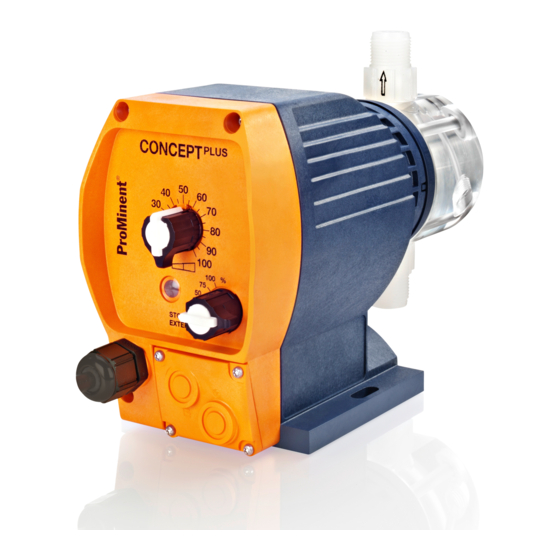
Overview of equipment Overview of equipment P_CO_0005_SW Fig. 2: Overview of equipmentCONCEPT plus Stroke length adjustment knob "External control" terminal (in "External" Fault / operating indicator (fault red / opera‐ operating mode, control via contact signal; tion green) optional) Multifunctional switch (stroke rates (in % of "Level switch"... -
Page 7: Safety Chapter
Observe the general limitations with regard to viscosity limits, chemical resistance and WARNI Denotes a possibly hazardous sit‐ density - see also ProMinent® resistance uation. If this is disregarded, you list in the Product Catalogue or at are in a life-threatening situation www.prominent.com! - Page 8 Safety chapter Safety notes WARNING! WARNING! Danger from hazardous substances! Possible consequence: Fatal or very Warning about personal and material serious injuries. damage The pump can start to pump, as soon as it Please ensure when handling hazardous is connected to the mains voltage. substances that you have read the latest safety data sheets provided by the manu‐...
- Page 9 – Only fit parts to metering pumps that have been tested and recommended by ProMinent. CAUTION! Warning against illegal operation Observe the regulations that apply where the unit is installed.
-
Page 10: Storage And Transport
Decontamination Declaration is submitted that has been completed correctly and in full by an authorised and qualified person on behalf of the pump operator. The "Decontamination Declaration Form" can be found at www.prominent.com. Ambient conditions... -
Page 11: Assembly And Installation
Assembly and Installation Assembly and Installation CAUTION! CAUTION! Warning of feed chemical spraying around Warning of destruction of the pump The pipes can loosen or rupture if they are An incorrect mains voltage or mains fre‐ not installed correctly. quency can irreparably destroy the metering pump. - Page 12 Assembly and Installation Installing the hose line CAUTION! Material damage possible due to power surges Should the pump be connected to the mains power supply in parallel to inductive consumers (such as solenoid valves, motors), inductive power surges can damage the control when it is switched off. –...
- Page 13 Assembly and Installation Install the suction line. To do this, shorten the free end of the suction line so that the foot valve hangs just above the base of the storage tank. With feed chemicals with impurities or sediment, shorten the free end of the suction line so that the foot valve hangs at least 50 mm above the base of the storage tank.
-
Page 14: Maintenance
Maintenance Maintenance Interval Maintenance work Personnel Quarterly* Technical personnel Check the metering diaphragm for damage** - refer to "Repair". Check that the hydraulic lines are fixed firmly to the liquid end. Check that the suction valve and discharge valve are correctly seated. -
Page 15: Repairs
Cleaning a valve Replacing the diaphragm All other repairs: Contact your responsible ProMinent branch! P_CO_0015_SW Fig. 4 If necessary take protective measures. Adhere to the safety data sheet for the feed chemical. - Page 16 Repairs Unscrew the diaphragm (3) completely from the drive axle. CAUTION! Remove the backplate (4) from the pump housing (6). Leakage may become apparent at a later stage. Check the condition of the safety dia‐ – Make sure that the leakage phragm (5) and replace if necessary.
- Page 17 Repairs Gently tighten the screws (1) and then – With PP and PV dosing heads, check tighten them diagonally. See below for the tightening torque again after three tightening torque. months! CAUTION! Leakage possible – Check the tightening torque of the screws after 24 hours of operation! Tightening torque Data...
-
Page 18: Faults
Faults Faults Fault description Cause Remedy Pump does not prime in Minor crystalline deposits on Take the suction hose out of the spite of full stroke motion the ball seat due to the valves storage tank and thoroughly flush and bleeding. drying out out the liquid end Major crystalline deposits on... -
Page 19: Decommissioning
Decommissioning Decommissioning WARNING! Danger from chemical residues There is normally chemical residue in the liquid end and on the housing after opera‐ tion. This chemical residue could be haz‐ ardous to people. – It is mandatory that the safety infor‐ mation relating to the "Storage, trans‐... -
Page 20: Technical Data
Technical data Technical data CNPb performance table for 180 strokes/min Type Minimum pump Minimum pump Connector Suc‐ Pri‐ Max. capacity capacity size tion ming priming lift* lift** pres‐ at maximum back at medium back pres‐ outside Æ sure on pressure sure x inside Æ... - Page 21 Technical data CNPb performance table for 240 strokes/min Type Minimum pump Minimum pump Con‐ Suc‐ Pri‐ Max. capacity capacity nector tion ming priming size lift* lift** pres‐ at maximum back at medium back pres‐ sure pressure sure outside Æ on the x inside Æ...
- Page 22 Technical data Material Specifications Material type Dosing head Suction/pressure Seals Valve balls connector Polypropylene Polypropylene PTFE Ceramic Polypropylene Polypropylene EPDM Ceramic Polypropylene Polypropylene FPM-B Ceramic Clear acrylic PTFE Ceramic Clear acrylic EPDM Ceramic Clear acrylic FPM-B Ceramic PVDF PVDF PTFE Ceramic Diaphragm: with a PTFE coating Housing: PPE, fibreglass-reinforced...
- Page 23 Technical data Technical data for the inputs (contact input, level input) Data Value Unit Voltage with open contacts 5 ± 0.5 VDC Input resistance 12 ± 0.5 ㏀ Short circuit current 0.5 ± 0.05 mA Maximum level for "0" signal 1.0 V Maximum level for "1"...
- Page 24 Technical data Climate Data Value Unit Maximum air humidity*: 95 % relative humidity *non-condensing Enclosure rating and protection class Protection against contact and humidity: IP 65 in accordance with IEC 529, EN 60529, DIN VDE 0470 Part 1 Degree of protection: 1 - mains power connection with protective earth conductor Mahar Fan Abzar...
- Page 25 Technical data Shipping weight Specification Value Unit Shipping weight Sound pressure level Sound pressure level LpA < 75 dB in accord‐ ance with EN ISO 20361 (Type 1000) Sound pressure level LpA < 70 dB in accord‐ ance with EN ISO 20361 (all other types) at maximum stroke length, maximum stroke rate, maximum back pressure (water) Mahar Fan Abzar...
-
Page 26: Accessories
Accessories Accessories Suction lances Article Order no. Suction lance for 200 l drum, storage tank opening 2“ DIN 570, PPE 1022511 Suction lance for 200 l drum, storage tank opening 2“ DIN 570, PCB 1022512 Suction lance for storage tank 5 - 50 l drum, storage tank opening d50, 1022645 Suction lance for storage tank 5 - 50 l drum, storage tank opening d50, 1022644... -
Page 27: Dimensional Drawings
Dimensional drawings Dimensional drawings Dimensions in mm Mahar Fan Abzar... - Page 28 Dimensional drawings CONCEPT plus with bleed valve, PP and NP 10.5 31.5 92.5 P_CO_016_SW Types 0309-0213 1000-0704 Mahar Fan Abzar...
- Page 29 Dimensional drawings CONCEPT plus without bleed valve, PP and NP 10.5 31.5 92.5 P_CO_017_SW Types 0309-0213 1000-0704 Mahar Fan Abzar...
- Page 30 Dimensional drawings CONCEPT plus PV 10.5 31.5 92.5 P_CO_0018_SW Types 0309-0213 1000-0704 Mahar Fan Abzar...
-
Page 31: Ec / Eu Declaration Of Conformity For Machinery
EC / EU Declaration of Conformity for Machinery In accordance with DIRECTIVE 2006/42/EC OF THE EUROPEAN PARLIAMENT AND OF THE COUNCIL, Appendix I, BASIC HEALTH AND SAFETY REQUIREMENTS, section 1.7.4.2. C. ProMinent GmbH Im Schuhmachergewann 5 - 11 D - 69123 Heidelberg,... -
Page 32: Installation Instructions For External + Level Retrofit Kit Cnpb (Part No. 1022099)
Installation instructions for External + Level retrofit kit CNPb (Part no. 1022099) Installation instructions for External + Level retrofit kit CNPb (Part no. 1022099) Connector for external control (External oper‐ Unscrew the cover at the bottom right ating mode) on the front of the pump. Punch open the marked openings. - Page 33 Mahar Fan Abzar...
- Page 34 Mahar Fan Abzar...
- Page 35 Mahar Fan Abzar...
- Page 36 ProMinent GmbH Im Schuhmachergewann 5-11 69123 Heidelberg Germany Telephone: +49 6221 842-0 Fax: +49 6221 842-419 Email: info@prominent.com Internet: www.prominent.com Heidelberg, 2, en_GB © 2010 Mahar Fan Abzar...
Need help?
Do you have a question about the CONCEPTplus CNPb and is the answer not in the manual?
Questions and answers