Table of Contents
Advertisement
Quick Links
• Never look at the UV lamp being lit with your naked eyes,
or it may cause pain in your eyes or visual impairment.
• This device is equivalent to Class II laser device. Never look at
the laser light, or it may cause pain in your eyes
or visual impairment.
MIMAKI ENGINEERING CO., LTD.
Operation Manual
D200871-18
Advertisement
Table of Contents

Related Manuals for MIMAKI UJF-605C


Summary of Contents for MIMAKI UJF-605C
- Page 1 • This device is equivalent to Class II laser device. Never look at the laser light, or it may cause pain in your eyes or visual impairment. MIMAKI ENGINEERING CO., LTD. D200871-18...
- Page 3 DISCLAIMER OF WARRANTY: THIS LIMITED WARRANTY OF MIMAKI SHALL BE THE SOLE AND EXCLU- SIVE WARRANTY AND IS IN LIEU OF ALL OTHER WARRANTIES, EXPRESS OR IMPLIED, INCLUDING , BUT NOT LIMITED TO, ANY IMPLIED WARRANTY OF MERCHANTABILITY OR FITNESS, AND MIMAKI NEITHER ASSUMES NOR...
- Page 4 Operation of this equipment in a residential area is likely to cause harmful interference in which cause the user will be required to correct the interference at his own expense. • In the case where MIMAKI-recommended cable is not used for con- nection of this device, limits provided by FCC rules can be exceeded.
-
Page 5: On This Operation Manual
Foreword Congratulations on your purchase of a MIMAKI "UJF-605C" model of UV ink jet printer. UV Inkjet Printer UJF-605C uses ultraviolet ray curing ink (UV ink), which has been recently developed. Read this Operation Manual carefully and make the most effective use of your printer. -
Page 6: Table Of Contents
Table of contents Foreword ......................iii On this operation manual ..................iii Features ......................viii For safe operation ................... ix Pictorial signs ......................ix Example of pictorial signs ..................ix Precautions in use ....................xiv How to read this Operation Manual ............... xvii Display on the LCD and Indication of the Keys ........... - Page 7 Chapter 2 Basic operations Operation ....................... 2-2 Turning the power on ..................2-3 Displaying the information ..................2-4 Opening / closing covers ................2-5 Initial setting of inks ..................2-6 Setting the media ..................2-7 Types of media that can be used ................. 2-7 Front UV light-resistant curtain ................
- Page 8 Precautions for replacing or exchanging .............. 3-8 Precautions in handling the Anti-freezing liquid ........... 3-8 Regular maintenance for white ink .............. 3-13 Cleaning or replacing filter................3-15 Cleaning the undersurface of the carriage ..........3-16 Cleaning of the head guard plate ............... 3-16 Cleaning of the nozzle side ................
- Page 9 Select a head for small amount cleaning [HEAD MAINTE ] ....... 5-15 Replacing UV Lamp ..................5-16 Checking UV lamp irradiation duration .............. 5-16 Replacing UV lamp ..................... 5-16 Resetting UV lamp irradiation duration ............5-17 Setting UV lamp off duration ............... 5-18 Checking UV ink curing level ...............
-
Page 10: Features
Features The features of the device are described below. Together with the method of operation of the device explained in this manual, they help you understand how to use the device properly. Ultraviolet ray curing ink used Use of ultraviolet ray curing ink (UV ink), which has been recently developed, enables direct printing onto media. -
Page 11: For Safe Operation
For safe operation Pictorial signs Pictorial signs are used in this Operation Manual for safe operation of and in prevention of damages to the device. Pictorial signs and their meanings are given below. Read and fully understand before reading the text. •... - Page 12 WARNING • Be sure to setup the appropriate air-moving system in case of using the device in a closed room or a room with bad ventilation. *Cautions for constructing exhaust outlet Please observe the following things to prevent the device. The sharp of the exhaust outlet depends on your build- ing enviroment.
- Page 13 Never do the following WARNING Do not disassemble or remodel the device Handling of ink cartridges • Never disassemble or remodel the • Store ink cartridges and waste ink main unit of the printer and the ink tank in a place that is out of the reach cartridge.
- Page 14 • Be sure to use only the UV lamp prohibited. recommended by Mimaki, or it may • To prevent electrical shock, be sure cause fire or damages to the unit. to set OFF the main power circuit...
- Page 15 • Use the exclusive Anti-freezing liquid Entrust them to an industrial by Mimaki , or the heater may be waste disposal contractor, damaged. clarifying their contents. • If the Anti-freezing liquid or mixed soft water with anti-freezing liquid gets on •...
-
Page 16: Precautions In Use
Precautions in use CAUTION Warning labels Periodic exchange parts • This device is adhered with a • There are some parts which must be warning label. Be sure understand replaced by service men. You have firmly the warnings given on the to make a contract with distributors or dealers for after-sale service. - Page 17 CAUTION About hot parts Handling the Anti-freezing liquid • Be sure to store the Anti-freezing • The UV lamp and the interior of the liquid in a cold and dark place. UV irradiation device will have a very • Store the Anti-freezing liquid in a high temperature.
-
Page 18: Precautions In Installation
The UV lamp performance and service life are significantly affected by the UV irradiation and UV power supply units used. Never use those UV devices other than those recommended by Mimaki. We would take no responsibility for any troubles caused through the use of a UV devices not recommended by Mimaki. -
Page 19: How To Read This Operation Manual
How to read this Operation Manual Display on the LCD and Indication of the Keys In this Operation Manual, the characters displayed on the LCD of the operation panel and the keys used to operate the device are explained, together with the operation procedure. P.1-18. -
Page 20: Structure Of This Operation Manual
Structure of this Operation Manual This Manual consists of the following seven chapters to describe the handling of the device. Chapter 1 Before use This chapter describes the name and function of each section of the de- vice. Chapter 2 Operations This chapter describes a series of operations and settings, ranging from power-on to end of printing. - Page 21 Chapter 1 Before use This chapter describes the name and function of each section of the device as well as ink and media. Table of contents Installing the device................1-2 Configuration and function ..............1-4 Connecting the cables................ 1-10 UV unit and UV irradiation device ............1-12 Installing the ink cartridges ..............
-
Page 22: Installing The Device
Installing the device Where to install the device Secure a suitable installation space before assembling the device. The place of installation must have space required not only for the device itself but also for printing operation. Width Depth Height Gross weight About 2250 mm About 1570 mm About 1370 mm... - Page 23 When moving the device, it must be held the corners up by at least four persons. • When moving the device to a different place, contact local representative of Mimaki Engineering. If you move it, failure of damage may occur. Be sure to request a specialist to move the device.
-
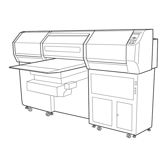
Page 24: Configuration And Function
Configuration and function The front Name Function Left maintenance cover Position for standby during printing. Equipped with a flushing tray and opened and closed during maintenance. Front cover It is opened when setting media or taking a corrective measure against a media jam. Even if the power switch is off, keep the front cover closed to perform the ink clogging preventive opera- tion. -
Page 25: The Rear
The rear Name Function Ink station Install the ink cartridges specified. IEEE1394 connector A 400 M bps interface connector compatible with -IEEE1394. Parallel connector Bidirectional parallel interface connector. (complies with IEEE1284) Air filter Clean an air for the blower table. Name Function D-SUB connector... -
Page 26: Operation Panel
Operation panel The operation panel that is used to operate the device. Display Displays a set item, a guidance error, etc. POWER lamp JOG keys [ ] [ ] [ ] [ ] It lights up (in green) when the They are used to shift the carriage power to the device is turned on. -
Page 27: Sub-Panel
Sub-panel The sub-panel is used for moving the table up/down, copying and setting blower ON/OFF. [COPY] key JOG keys [ ] [ ] Repeats printing of already Move the table up/down. printed data. P.2-23, 2-24) [Vacuum switch] Sets table ON/OFF with the blower. -
Page 28: Carriage
Carriage The carriage contains the print head for printing and the UV irradiation device; there are a Mark sensor and light pointer inside the print head cover.Depending on UV lamp condition, the carriage is positioned differently. The carriage sits in the left station cover during UV lamp ON. The carriage sits in the right station cover during UV lamp OFF. -
Page 29: Flushing Tray
Flushing tray Flushing tray is inside of the left maintenance cover at the front side. When printing head executes flushing operation, waste ink may be collected in the flushing tray. Clean the waste ink from the tray regulary. ( P.3-5) - 1-9 -... -
Page 30: Connecting The Cables
• Either of the two IEEE 1394 connectors can be used. • The computer is not provided with an IEEE 1394 board, contact your nearest RIP provider or MIMAKI sales office. IEEE 1284 interface is used Use an IEEE 1284 interface cable to connect the computer and the device together. It is possible to use an IEEE 1284 interface cable for connection between the computer and the device. -
Page 31: Connecting The Power Cable
Connecting the power cable • Connecting the power cable For supplying power to the device, the power distribution board work are required. Connecting the power cable cannot be installed by the customer. Contact your local distributor to call for service to connect the power cable as well as moving installation of the device. -
Page 32: Uv Unit And Uv Irradiation Device
UV unit and UV irradiation device UV unit The UV unit installed in the lower-right corner of this unit is interlocked with the UV irradia- tion device and UV indication lamps. UV irradiation device • Never look at the UV lamp being lit with your naked eyes. •... -
Page 33: About Functions Of Uv Lamp Status Indicator
About functions of UV lamp status indicator This section describes the functions of three UV lamp status indicator which placed under the power switch of this unit. The indicator represents three modes in combination. The UV lamp automatically goes OFF when printing is not carried out 30 minutes or more. When carrying out no printing long time (30 minutes or more), set the UV lamp OFF. -
Page 34: Mode For The Uv Lamp Status Indicator
Mode for the UV lamp status indicator Mode Description Description of indicator lamps Ready mode ON/blinking (green) When [REMOTE] or [TEST] key is pressed [Printing enabled] UV lamp being pre- and [TESTDRAW] is selected, preheating of heated (UV lamp the UV lamp starts. preheating completed When preheating is completed, the UV lamp (ON) -
Page 35: Installing The Ink Cartridges
Installing the ink cartridges Install the ink cartridges to the device. • When installing an ink cartridge, hold it laterally with the side containing the IC chip upward. After setting the main unit power ON, be • sure to carry out initial filling. P.2-6) Each color is displayed on the LCD as follows: Black : K, Cyan : C,... -
Page 36: Ink Cartridge And Ink Station
• Never disassemble the ink cartridge. • Never refill the ink cartridge with ink. Refilling the ink cartridge can cause a trouble. Remember that Mimaki assumes no responsibility for any damage caused by the use of the ink cartridge replenished with ink. -
Page 37: Types Of Media That Can Be Used
Types of media that can be used The following describes the sizes of media that can be used and the method of handling. Sizes of media that can be used Maximum 700 mm Minimum 600 mm Max. printing width 600 mm Max. -
Page 38: Menu Mode
Menu mode There are the following three mode in this device. Each of the three modes is explained below. < LOCAL > mode This is the mode in preparatory state. All keys are effective to enable setups. The device is able to receive data from computer, however, it will not perform printing. In this mode, it is possible to perform the following operations. - Page 39 Chapter 2 Basic operations This chapter describes a series of operations and settings, ranging from power-on to end of printing. Table of contents Operation ..................... 2-2 Turning the power on ................2-3 Opening / closing covers ..............2-5 Initial setting of inks ................2-6 Setting the media .................
-
Page 40: Operation
Operation The following shows a series of operations and settings, ranging from power-on to end of printing. For details on each item, refer to the reference page. Turn the power on P. 2-3 LOCAL MODE P. 2-6 *For the start first Initial setting of inks P. -
Page 41: Turning The Power On
Turning the power on 1. Turn on the power of the UV unit. Tilt the power switch toward the “ I ”side. 2. Turn on the power to the device. Tilt the power switch toward the “ I ”side. When the power is switched on, the LCD first displays “BOOT”... -
Page 42: Displaying The Information
4. The device enters the LOCAL mode. 5. Turn on the power to the computer which << LOCAL >> is connected to the device. Displaying the information Display the device informations by pressing [ENTER] key. The following explains the proce- dure for displaying information in local mode. -
Page 43: Opening / Closing Covers
Opening / closing covers • Keep all the covers closed during printing operation. Opening all the covers during printing interrupts image printing and disables continuous processing. • make sure to open and close the cover with holding the handles. Doing so while holding the resin face may cause damage to the device. -
Page 44: Initial Setting Of Inks
Initial setting of inks When using the device for the first time, it is necessary to install ink cartridges in the de- vice. When replacing ink, see P.2-27. STEPS: 1. Check that an ink cartridge has been inserted in the ink station up to the prede- termined position and set. -
Page 45: Setting The Media
Setting the media All absorption holes on the table may not be blocked with media of a certain size. If neces- sary, block such absorption holes with a sheet such as paper, film, etc. thinner than the media used. If the media is likely to go out of alignment, affecting the printing, additionally fix the media with adhesive tape. - Page 46 Attaching the front UV light-resistant curtain Handle of the 1. Attach the large curtain to the handle part of front cover the front cover. Front cover Attach it with the magnetic part up. Magnetic parts of the curtain 2. Insert the curtain all the way until it hit a wall into the handle.
-
Page 47: Before Setting Media
before setting media We have three ways before setting media. • Entering head gap value .... Enter and fix the head gap value. • Media thickness known ....[Sense mode] or [Continue] mode. Media thickness unknown ..[Media thickness] mode. •... -
Page 48: Selecting [Gap Check]- [Select] For Head Gap Adjustment
Selecting [GAP CHECK]- [SELECT] for head gap adjustment Select the check method for gap adjustment during printing based on the head gap value entered. There are three check methods available. Select the check method to be used according to the media to be used. When the thickness of media is unknown Sense mode ...... - Page 49 When the thickness of media is known The allowable thickness range of media is 0 to 50 mm. Media thickness ..When the thickness of media is known, enter the value. The head gap is not adjusted for printing. • When changed the thickness of media, specify the exact thickness or the print head and UV irradiation device may be damaged.
- Page 50 11. Enter the thickness value of media by MEDIA THICKNESS pressing the [ ] or [ ] keys and then :50mm press the [ENTER] key. GAP CHECK 12. Press the [ENTER] key. CHECK SELECT <ent> Table raise up unto the height of the media. Adjust the table height that the highest part of the media is to be same as the head gap setting value.
-
Page 51: Checking Head Gap
Checking head gap When continue mode has been selected, be sure to check the gap. The table can be ad- justed in height, according to thickness of a media used for printing. The table height must be set according to the media thickness. If the table height is too low, it may affect the printing quality and even damage the media or the device itself. - Page 52 8. Press the [ENTER] key ** TABLE FALL** PLEASE WAIT The table moves upward and, at the same time, the head gap is automatically adjusted. 9. When adjustment has completed, [CHECK GAP CHECK CHECK START <ent> START] is restored. 10. Press the [END] key twice, the device <<LOCAL>>...
-
Page 53: Establishing The Origin And The Print Area
Establishing the origin and the print area Initial value The origin and the print area are set as following by default until they are changed: 60mm Effective printing area Media Out put direction 60mm Origin - 2-15 -... -
Page 54: Setting Printing Origin
Setting printing origin When printing in an area not initially set, change the printing origin. The printing origin can be set in two ways: • Setting printing origin using jog keys • Setting printing origin using [ORIGIN] setting from the FUNCTION menu. Setting printing origin using jog keys STEPS: <<LOCAL>>... -
Page 55: Setting Precisely The Origin ([Function] - [Origin])
Setting precisely the origin ([FUNCTION] - [ORIGIN]) To precisely set the origin of coordinates, set its X- and Y- coordinates from the FUNCTION menu. This setting value become the origin position (0, 0). • After setting the origin position (0, 0), it is not cleard even when the power is turued off. - Page 56 8. Select [Y OFFSET] by pressing the [ ] or ORIGIN [ ] keys. Y OFFSET <ent> Set the Y origin. ORIGIN ( 580mm) 9. Press the [ENTER] key. Y OFFSET 20mm 10. Enter the setting value by pressing the [ ] ORIGIN ( 450mm) or [ ] keys.
-
Page 57: Checking And Solving Nozzle Clogging
Checking and solving nozzle clogging Make test printing to check whether there is nozzle clogging or other printing failures. If the finished test pattern shows any sign of abnormal conditions, carry out the cleaning function. Light Light Cyan(Lc) Magenta(Lm) Black(K) Cyan(C) Magenta(M) Yellow(Y) - Page 58 Abnormal pattern If an abnormal pattern like the one shown on the right is printed, clean the head. There are two types of cleaning. Select one of them according to the result of pattern printing. Normal : Select this if any line is bent. Hard Select this if not any recovering abnormal pattern.
-
Page 59: Printing An Image From Source Data
Printing an image from source data Starting the printing operation The following describes the method of printing. For various function settings necessary for printing, refer to “CHP5 Setting Function”. • If the temperature in the water heater or in the UV device has not reached the predetermined value, a message is indicated. - Page 60 ERROR 35 • When no registration marks are MARK DETECT detected, an error is indicated and the local screen is restored. When [ERROR35 MARK DETECT] is indicated, set [FUNCTION] menu - [MARK SETTING] again and then check the registration marks. Resolution: 600 DPI 4.
-
Page 61: Printing Repeatedly (Copy)
Printing repeatedly (COPY) Data (1 edition) printed immediately before is printed again. This operation can be carried out from the operation panel or sub-panel in the same way. • If the temperature in the water heater or in the UV device has not reached the predetermined value, a message is indicated. -
Page 62: Interrupting The Printing Operation
Interrupting the printing operation To interrupt the printing operation, stop the carriage and erase (the receive data) from the device. STEPS: 1. Press the [REMOTE] key to stop the print- << LOCAL >> ing operation. 2. If data is being transmitted from the com- puter to the device, stop the data trans- mission. - Page 63 2. During waiting for printing in the REMOTE COPY < MEM. > mode, press the [COPY] key to put the device into the MEMORY mode. The MEMORY mode can print the receiving data as well as the REMOTE mode. As the MEMORY mode can copy multi editions, printing information of each edition can be memo- rized.
-
Page 64: Clear The Number Of Copies
9. Press the [ ] or [ ] key to select the over- COPY CNT: 1 printing edition. EDIT : 1 2 2 - The following display indicates the second edition two times after printing the first edition. [-] indi- cates no printing. -
Page 65: To Replenish Ink, Set A New Ink Cartridge In The Ink Station
To replenish ink, set a new ink cartridge in the ink station If ink in the cartridge comes to an empty, the corresponding message appears. Printing can be continued but ink may run out during printing. Immediately put a new ink cartridge. •... -
Page 66: Ink Cartridge Trouble
Ink cartridge trouble When an ink cartridge trouble is detected, a warning message appears and printing, clean- ing and all other activities that use ink are deactivated. When this is the case, replace the ink cartridge in question immediately. • Do not leave the ink cartridge unreplaced for a long time as this will cause the nozzle clogging and the printer must be repaired by a service person. -
Page 67: Turning The Power Off
Turning the power off To turn the power off, check first whether or not there is data received and there remains data that has not yet been output in the device. • Leave all the covers closed. • Perform the operation for the turning off of UV irradiation device, and turn the device off when Orange Cooling lamp has been gone dark. - Page 68 - 2-30 -...
- Page 69 Chapter 3 Daily care This chapter describes daily care. For purchasing maintenance supply, contact your local distributor or dealer. Swab (Order No. :SPC-0384) Washing liquid (Order No. :SPC-0385) Table of contents Routine maintenance ................3-2 In cace defective printing is not resolved ..........3-3 Cleaning flushing tray................
-
Page 70: Routine Maintenance
Routine maintenance Be sure to conduct maintenance works for the device when necessary or periodically so as to use the device for a long time while keeping its printing accuracy. When the device is left unused for a long period of time •... -
Page 71: In Cace Defective Printing Is Not Resolved
In cace defective printing is not resolved When the station interior is severely contaminated or defective printing is not resolved after executing the head cleaning function ( P.2-20), clean the suction nozzle and cap using the cleaning kit. The cleaning kit contains the following contents. Do not use alcohol or water. •... - Page 72 Contact your nearest sales agency or Mimaki sales office. • Contact your nearest sales agency or Mimaki sales office to order the exclu- sive cleaning swab. Suction nozzle cover 9. Wipe the adherent ink which got on the cap rubber or inside the suction nozzle cover with the exclusive cleaning swab.
-
Page 73: Cleaning Flushing Tray
Cleaning flushing tray Wipe off waste ink from the flushing tray. Tools necessary for cleaning: Maintenance cleaning liquid, Gloves, Goggles, Paper towel • When cleaning the ink station and head, be sure to wear the supplied goggle and gloves since you may get ink in your eyes. •... - Page 74 8. Wipe off the waste ink from the flushing tray with the paper towel containing main- tenance cleaning liquid. Take the caked ink off by patting the tray. • Make sure to take the caked ink off completely, or it may cause head damage by the remaining caked ink.
-
Page 75: When The Waste Ink Tank Becomes Full
When the waste ink tank becomes full Waste ink used for cleaning the heads will gather in the waste ink tank. • Contact your local MIMAKI distributor or call a local MIMAKI office if you need a spare waste ink tank. -
Page 76: Replacing Waterin Water Heater Tank
Precautions in handling the Anti-freezing liquid • Be sure to wear goggles and gloves for handling the Anti-freezing liquid. • Use the exclusive Anti-freezing liquid by Mimaki , or the heater may be damaged. • If the Anti-freezing liquid gets on the skin or clothes, immediately wash it off with soap. - Page 77 Replacing antifreezing liquid 1. Press the [FUNCTION] key from the LO- << LOCAL >> CAL mode. FUNCTION DATA CLEAR < ENT > FUNCTION 2. Press the [ ] or [ ] keys until the display MAINTENANCE < ENT > gives the indication [MAINTENANCE]. MAINTENANCE 3.
- Page 78 9. Unlock catch clips on both sides of the cover. 10. Engage the water heater handle with the hook. • When engaging the handle with the hook, take care to avoid bending the cables or tubes or pulling them with excessive force, or it may cause malfunction of the water heater.
- Page 79 12. Move waste water in the hot-water tank to a polyethylene tank. • When moving water, take care not to spill it. If spilled, be sure to wipe it off. • Discard the waste water from the hot- water tank according to the local regulations of the area this unit is used.
- Page 80 18. Again, move waste water in the hot-water tank to a polyethylene tank. • When moving water, take care not to spill it. If spilled, be sure to wipe it off. • Discard the waste water from the hot- water tank according to the local regulations of the area this unit is used.
-
Page 81: Regular Maintenance For White Ink
Regular maintenance for white ink White ink is easier precipitate than other inks. In case without printing more than two weeks, white ink may cause precipitate in ink car- tridge or inside of the device. And nozzle clogging has occurred and the normal printing result is not able to obtain by precipitation. - Page 82 8. Slowly shake the white ink cartridge more than twenty times right and left. To prevent ink from leaking when you shake the cartridge, wear gloves and firmly cover the A part of the upper surface of the cartridge and the B part of the bottom surface of the cartridge with paper towels.
-
Page 83: Cleaning Or Replacing Filter
Cleaning or replacing filter This unit contains a filter for the table. When the filter is clogged, the media absorbability will be weakened. If filter is soiled with dusts, clean it with vacuum cleaner, etc. If the filter is clogged by ink adhesion, replace the filter. STEPS: 1. -
Page 84: Cleaning The Undersurface Of The Carriage
Cleaning the undersurface of the carriage Cleaning of the head guard plate Ink drops may appears on the head guard plate on the undersurface of the carriage, result in inferior printing or ink blot on the media. Make sure to perform cleaning regularly the undersurface of the carriage. - Page 85 • Do not touch the head and nozzle part to avoid the damage. • Contact your nearest sales agency or Mimaki sales office to order the exclu- sive cleaning swab. 8. After cleaning, close the front cover and then turn the main unit power on.
-
Page 86: Cleaning Of The Nozzle Side
Cleaning of the nozzle side Perform the following thing when ink drops by printing are generated on the nozzle side of the head or media is stained by dropping ink drops. STEPS: 1. Press the [FUNCTION] key from the LO- <<... - Page 87 7. Display ON / OFF of the wipe by pressing WIPE HEAD the jog key [ ] or [ ] . COLOR : KCMYcmWS OFF is displayed as [-]. 8. Press the [ENTER] key. 9. Select the number of wiping (1 to 9) by WIPE HEAD pressing the jog key [ ] or [ ] .
- Page 88 - 3-20 -...
- Page 89 Chapter 4 Setting function This chapter describes setting functions. Table of contents Application functions ................4-2 Registering two or more printing conditions at a time (Selecting a type) ................. 4-4 Setup functions ..................4-5 Setting the operation of the registration mark detection [MARK SENSOR] .................
-
Page 90: Application Functions
Application functions Of the menus that are provided for setting printing conditions for the device, the menu for setting up the device functions is called the function menu. In order to set printing condi- tions properly, it is necessary to understand the structure and operation of the function menu. -
Page 91: Basic Operations Of Menus
Basic operations of menus This section describes how to change over the operation modes and how to operate the menus. The following gives the key operation flow to invoke menus. For detailed menu configuration, refer to Appendix. FUNCTION ENTER << LOCAL >> FUNCTION DATA CLEAR DATA CLEAR... -
Page 92: Registering Two Or More Printing Conditions At A Time (Selecting A Type)
Registering two or more printing conditions at a time (Selecting a type) Register a sequence of printing conditions set in the FUNCTION mode in the memory of the device. By allocating the sequence of printing conditions to any of Types 1 through 4, it is possible to reuse the same printing conditions registered by type. -
Page 93: Setup Functions
Setup functions The function mode provides 9 set functions and a set function contains 9 set functions. The set functions are outlined below. Function names Summary Data clear P.2-24 Data received are cleared when aborting the printing or in prior to the execution of the [COPY] function. - Page 94 [UV Level] Adjusts the light intensity. Normally, set [NORMAL]. Also setting [LAYER] allows the setup the UV level for at most 4 layers according to each layer. [NORMAL] : Standard light intensity [HIGH] : Strong light intensity [LOW] : Weak light intensity [NONE] : Close the shatter of the UV lamp to print.
- Page 95 [Color pattern] Print a color pattern on the left edge of media to check the nozzle out while plotting. [ON] : Color pattern is printed at +20mm from left edge of maximum printable area. [OFF] : Color pattern is not printed. Color pattern Image Image...
-
Page 96: Setting The Operation Of The Registration Mark Detection [Mark Sensor]
Setting the operation of the registration mark detection [MARK SENSOR] Before detecting registration marks, make settings necessary for detection. In addition, check the response of the Mark sensor. Registration marks are detected when printing. ( P.2-21) Set the operation of the registration mark detection [MARK SETUP] This function is used to automatically detect a registration mark. - Page 97 TYPE1 60 mm or more from the sheet backend 60 mm or more from the sheet B: 50 mm or more TYPE2 60 mm or more from the sheet backend 60 mm or more from the sheet B: 50 mm or more - 4-9 -...
- Page 98 Operation settings for detection of marks The settings of the following three functions are specified when detecting a mark. An underline shows the initial value. Function Setting Description MARK DETECT Data printing or copy printing is to be carried out on ordinary media. Always When the registration mark positions are different for each printing operation, registration marks are detected using the light pointer for each data or copy printing...
- Page 99 Set the operation for registration marks detection STEPS: 1. Make sure that the Local mode is dis- << LOCAL >> played. FUNCTION 2. Press the [FUNCTION] key. DATE CLEAR < ENT > 3. Select the [MARK SENSOR] by pressing FUNCTION MARK SENSOR <...
-
Page 100: Check The Sensor For The Registration Mark Detection [Mark Check]
Check the sensor for the registration mark detection [MARK Check] Check the sensor. Registration mark condition Printed registration mark is required to fulfill all the following conditions. * The registration mark length must be 4 - 40mm on a side. * The line width of mark shall be equal to or more than 0.3 mm and equal to or less than 0.5 mm. - Page 101 8. Press the [ENTER] key. MARK SENSOR MARK CHECK :ent The registration mark detection starts. When no registration marks are detected, an error is indicated. 9. The registration mark detection com- pletes. Movement of Mark sensor Plus Minus Minus direction direction direction Start...
-
Page 102: Turning Off Uv Irradiation Device [Uv Lamp Off]
Turning off UV Irradiation device [UV LAMP OFF] The UV irradiation device automatically goes OFF when no printing is carried out 30 min- utes or more. When printing is to be carried out with a long interval, the UV lamp can be set OFF to make the UV lamp service life longer. -
Page 103: Change The Display Language [Display]
Change the display language [DISPLAY] Display language enable to change Japanese or English. Print default is English. This procedure explains how to change Display language to Japanese. Set Japanese display mode. STEPS: 1. Make sure that the mode is LOCAL mode. <<... - Page 104 - 4-16 -...
- Page 105 Chapter 5 Maintenance This chapter describes maintenance procedures including how to resolve deteriorated printing quality and replace the UV lamp, so that this unit can be used in good conditions. Table of contents Maintenance of the device ..............5-2 Drawing setup conditions [LIST] ............5-3 When media thickness is changed [Print Adjust] .........
-
Page 106: Maintenance Of The Device
Maintenance of the device The term “maintenance” as used herein refers to the operation that has to be performed to keep the device in good operating condition. To carry out maintenance of the device, select [MAINTENANCE] from the function menu and make the necessary settings. -
Page 107: Drawing Setup Conditions [List]
Drawing setup conditions [LIST] This function outputs the current settings of the device. They are useful in carrying out maintenance of the device. 1.SET UP : Indicates a value that is specified with the FUNCTION. 2.PRINT ADJUST : Indicates a correction value for dot position. 3.VERSION : Indicates the version of the firmware and memory capacity of the device. -
Page 108: When Media Thickness Is Changed [Print Adjust]
When media thickness is changed [Print Adjust] When the head height is adjusted, be sure to correct the dot positions. This function corrects the dot positions to ensure that the accurate printing result is ob- tained. The dot positions are corrected by comparing the ink dropping positions on each of the six test patterns between the two printing directions. - Page 109 4. Press the [ENTER] key. * * DRAW * * PLEASE WAIT Printing of the test patterns for the correction of dot position starts. There are six types of test patterns that are printed. 5. Press the [ ] or [ ] keys to correct the dot PRINT ADJUST position of pattern 1.
-
Page 110: Cleaning The Station Interior [Station]-[Carriageout]
Cleaning the station interior [Station]-[CarriageOut] Move the carriage when cleaning the station interior. • Do not move the carriage out of the capping station by hand. Use the appropriate operation key to move the carriage. STEPS: 1. Select the [STATION] from the [MAINTE- MAINTENANCE STATION <... -
Page 111: If Nozzles Are Clogged Even After The Cleaning Function Is Executed
If nozzles are clogged even after the cleaning function is executed If nozzle clogging is resolved after HEAD CLEANING ( P 2.20) perform the following functions. STEPS: 1. Select the [FILL UP INK] from the [MAIN- MAINTENANCE FILL UP INK <... -
Page 112: Regular Wiping Function [Int. Wiping]
Regular wiping function [INT. WIPING] Use this function to prevent the ink spray on the print head surface. This function enables to wipe off the condensed ink as wiping the nozzle at intervals after specified number of plotting. STEPS: 1. Select the [INT. WIPING] from the [MAIN- MAINTENANCE INT. -
Page 113: Changing The Ink Set [Ink Set]
Changing the ink set [INK SET] The standard ink set for this unit has 7 colors (black, cyan, magenta, yellow, light cyan, light magenta and white). You may change it to the following ink sets: *Changing to 6-color ink set (only 6 colors, white ink is not used) *Changing to 8-color ink set with addition of spot color *Changing to spot color instead of White ink •... - Page 114 7. Press the [ENTER] key. **WASHING** PLEASE WAIT 8. When the right is shoen, set the cleaner INK SET :******W cartridge. SET CLEAN TOOL 9. Press the [ENTER] key. **WASHING** The cleaner is sucked in and cleaning is per- PLEASE WAIT formed.
-
Page 115: Changing To 8-Color Ink Set With Addition Of Spot Color
Changing to 8-color ink set with addition of spot color There are two kinds of ink set in this ink set. 1. Uv-8 [KCMYcmWS] : The ink set which spot ink is added to 7-color ink set. 2. Uv-8 [KCMYcmSs] : The ink set which white ink of the 7-color ink set is changed to spot color and one more spot ink is added as 8th color. -
Page 116: Changing White Ink To Spot Color
Changing white ink to spot color The following procedures explain bout changing from 7-color ink set to 7-color ink set using spot ink instead of White ink. STEPS: MAINTENANCE 1. Select the [INK SET] from the [MAINTENANCE]. INK SET < ent > P.5-2) INK SET 2. - Page 117 10. When the right is shown, remove the INK SET :******W cleaner cartridge. REMOVE TOOL 11. Press the [ENTER] key. **WASHING** PLEASE WAIT The cleaner is discharged to the waste ink tank. 12. When the right is shown, set the spot ink cartridge.
-
Page 118: Ink Exchanging Procedure
Ink exchanging procedure Ink exchanging is performed as following procedure. STEPS: MAINTENANCE 1. Select the [INK CHANGE] from the [MAIN- INK CHANGE < ent > TENANCE]. ( P.5-2) INK CHANGE COLOR :KCMYcmW 2. Press the [ENTER] key. INK CHANGE 3. Select the print head color by pressing COLOR :KCMYcmW the [ ] or [ ] keys. -
Page 119: Select A Head For Small Amount Cleaning [Head Mainte ]
Select a head for small amount cleaning [HEAD MAINTE ] Select a head to execute small amount cleaning when turned on power. STEPS: MAINTENANCE 1. Select the [HEAD MAINTE] from the HEAD MAINTE < ent > [MAINTENANCE]. ( P.5-2) 2. Press the [ENTER] key. HEAD MAINTE. -
Page 120: Replacing Uv Lamp
When the irradiation duration has exceeded the predetermined period of time, a message appears asking you to replace the UV lamp. When this message has appeared, contact your nearest sales agency or Mimaki sales office to replace the UV lamp as soon as pos- sible. -
Page 121: Resetting Uv Lamp Irradiation Duration
Resetting UV lamp irradiation duration After replacing the UV lamp, reset the irradiation duration stored in this unit. STEPS: 1. Select the [UV LAMP] from the [MAINTE- MAINTENANCE UV LAMP <ENT> NANCE]. ( P.5-2) 2. Press the [ENTER] key. UV LAMP LEVEL CHECK <ent>... -
Page 122: Setting Uv Lamp Off Duration
Setting UV lamp off duration Set the UV lamp OFF duration stored in this unit. CONT. IRR. [OFF] ..UV irradiation device turns the lamp off automatically according to setting value. The initial setting value is 30 minutes. CONT. IRR [ON] ..... UV lamp is always lighting on. When turning the lamp off action, refer to the “ Turning off UV irradiation device”... -
Page 123: Checking Uv Ink Curing Level
Checking UV ink curing level As the UV lamp is deteriorated, the ink curing level may be lowered. Check the UV ink curing level and adjust the UV lamp light intensity, if necessary. UV ink curing check test pattern 6.25% Feeding direction 100% 25mm... - Page 124 6. Select the resolution for the test pattern HARDEN CHK by pressing the [ ] or [ ] keys. : 600 x 600 HARDEN CHK 7. Press the [ENTER] key. QUALITY : STD HARDEN CHK 8. Select the quality for the test pattern by QUALITY : HIGHspd pressing the [ ] or [ ] keys.
-
Page 125: Adjusting Uv Light Level
Adjusting UV light level STEPS: 1. Make sure that the Local mode is dis- <<LOCAL>> played. 2. Press the [FUNCTION] key. FUNCTION DATA CLEAR <ENT> FUNCTION 3. Select the [SETUP] by pressing the [ ] SET UP <ENT> key. TYPE * 4. - Page 126 10. Select the light level by pressing the [ ] or TYPE * [ ] key. LAYER 2 :NORMAL When selecting the [INVALID], the layer is printed by the light level of the previous layer after that. Ex.: For 4 layers, select the [INVALID] of the layer 3 and the light level of the layer 1 and 2 become effective.
-
Page 127: Uv Illumination Level Check
30%. In case the illumination level goes down significantly, contact your nearest sales agency or Mimaki sales office. The UV lamp could be broken. UV illumination level goes down gradually, not suddenly, without flickers of light after 1000 hours using. - Page 128 Steps to checking the level; 1. Make sure that the LOCAL mode is dis- << LOCAL >> played. FUNCTION 2. Press the [FUNCTION] key. DATA CLEAR < ENT > 3. Select the [MAINTENANCE] by pressing FUNCTION MAINTENANCE < ENT > the [ ] or [ ] keys.
- Page 129 10. Remove the Flashing tray and then, set the UV illuminometer. Setting the UV illuminometer A. Set the UV illuminometer BKT 1 so that the bracket touches the device. B. Set the edge of the illumination sensor to the UV illuminator BKT 1. Turn up the sensor hole to pass through the bracket hole.
- Page 130 F. Cover the illuminometer BKT 2 with match- ing the upper left coner and positioning the handle at upper right. 11. Press the [ENTER] key after setting the UV UV LEVEL CHECK SET THE TOOL :ent illuminometer. PLEASE CLOSE 12. Close the left maintenance cover. THE LEFT COVER 13.
- Page 131 17. After verifying the level, press the [EN- UV LEVEL CHECK CHK THE TOOL :ent TER] key. 18. Press the [ ] to terminate the illumination UV LEVEL CHECK check. Press the [ ] key and then finish CHECK< >FINISH the level check.
-
Page 132: Prevent The Nozzle Clogging Of Spot Color [Sp.refresh]
Prevent the nozzle clogging of spot color [SP.REFRESH] To prevent the head nozzle clog, this unit performs refresh while printer is turned on. How- ever the characteristic of white ink is different from other inks, therefore nozzle out occurs even performing the refresh. In this case change the head refresh operation, where white ink is installed, so as to suitable for the white ink. -
Page 133: Displaying Device Information [Information]
Displaying device information [INFORMATION] Displays the firmware version and serial number of this device. If trouble occurs, please inform the dealer or MIMAKI sales office of the contents of the trouble as well as this information. STEPS: 1. Select the [INFORMATION] from the MAINTENANCE [MAINTENANCE]. -
Page 134: Set The Type Of The Cap Rubber [Cap Rubber]
Set the type of the cap rubber [CAP RUBBER] After replacing the cap rubber, set the type of the cap rubber newly attached. STEPS: 1. Select the [CAP RUBBER] from the [MAIN- MAINTENANCE TENANCE]. ( P.5-2) CAP RUBBER < ent > 2. - Page 135 CHAPTER 6 When abnormal conditions are encountered Chapter 6 describes corrective measures to be taken in the case where an abnormal phenomenon arises on the device and where an error message is given on the display. Table of contents Before taking a phenomenon as a sign of failure ........ 6-2 If image quality declines ...............
-
Page 136: Before Taking A Phenomenon As A Sign Of Failure
LCD are described in this section. Be sure to take the following measures before taking the trouble as a sign of failure. If the measures fail restore the device to the normal state, contact your local MIMAKI distributor or MIMAKI office to call for service. The device cannot be energized More often than not, this is due to improper connection of the power cable. -
Page 137: If Image Quality Declines
Take measures in accordance with actual state of the picture. If the measures fail restore the device to the normal state, contact your local MIMAKI distributor or MIMAKI office call for service. Lines/thin spots are obvious occur Corrective measure : Execute the head cleaning. -
Page 138: Troubles For Which Error Messages Are Given On The Lcd
Troubles for which error messages are given on the LCD If something is wrong with the device, the buzzer sounds and a corresponding error mes- sage is given on the LCD. Take an appropriate corrective measure in accordance with the message. -
Page 139: Warning Message
! Kind of INK cartridge is different from the cartridge. COLOR :KCMYcmW previous one. The loaded ink cartridge is not Use the ink specified by MIMAKI. ! NonORIGINAL INK MIMAKI genuine. COLOR :KCMYcmW Attach the ink cartridge(s) corre- ! WRNING INK IC... -
Page 140: Error Messages
If any error message is given on the LCD, turn off the power to the device and turn it on after a while. If the same error message appears again on the LCD, contact your local MIMAKI distribu- tor or MIMAKI office to call for service. -
Page 141: Error Message
Error message Cause Corrective measure Improper operation has been Turn off the power to the device and ERROR 20 conducted on the operation panel. turn it on after a while. If the same I / F BOARD error message appears again on the LCD, contact your local distributor to call for service. - Page 142 Warning message Cause Corrective measure The X motor has been overload. ERROR 40 Turn off the power to the device and MOTOR X turn it on after a while. If the same error message appears again on the LCD, contact your local distribu- The Y motor has been overload.
-
Page 143: Appendix
Appendix This appendix describes the specifications and components the de- vice, function menu structure. Table of contents Basic specifications ................A-2 Specification for ink ................A-3 Position of the warning label ............... A-4 Function flowchart ................A-7 - A-1 -... -
Page 144: Basic Specifications
IEEE1394 compliant, IEEE1284 compliant Table Bi-direction port x 4 Command MRL-II B (ESC/PV.2 base, MIMAKI original command) Noise during standby : Less than 55 dB (FAST-A, Front & Rear & Left & Right 1 m) during continuous printing : Less than 65 dB... -
Page 145: Specification For Ink
Item UJF-605C Weight Packing box Approx. 420 kg Outside Width 2250 mm dimensions Depth 1570 mm or less Height 1370 mm or less Laser sensor (Laser Sensor Unit) Class ll Laser Product Maximum output : Pulse Duration 3.5µs Wave length... -
Page 146: Position Of The Warning Label
Position of the warning label This device is adhered with the warning label. Be sure to fully understand the warning given on the labels. In the case where any of the warning label has become so soiled that the warning message is illegible or has come off, purchase a new one from your local distributor or our office. - Page 147 No. Reorder No. Reorder No. No. ReorderNo. Reorder No. M901607 M903764 M903747 M903763 WARNING ULTRAVIOLET RADIATION M904131 M903946 WARNING AVOID EXPOSURE ULTRAVIOLET - Laser radiation is RADIATION emitted from this aperture. M904148 M903330 M904130 M963239 This product complies with 21 CFR chapter l and subchapter J.
- Page 148 - A-6 -...
-
Page 149: Function Flowchart
Function flowchart TEST KEY: TEST TEST ENTER << LOCAL >> TEST DRAW TEST DRAW NOZZLE CHK<ENT> ^ , v ENTER ENTER ENTER HARDEN CHK TEST DRAW HARDEN CHK TEST DRAW : 300 X 300 HARDEN CHK <ENT> QUALITY :STD :300 x 300 :STD, FINE, HIGHspd :600 x 600 :1200 x 1200... - Page 150 FUNCTION KEY: FUNCTION ENTER FUNCTION << LOCAL >> FUNCTION DATA CLEAR DATA CLEAR <ENT> , ^ , v FUNCTION ENTER FUNCTION UV LAMP OFF UV LAMP OFF <ENT> START : ent *Setting the media thickness mode , ^ , v FUNCTION ENTER ENTER...
- Page 151 CONTINUE..ENTER ENTER MAINTENANCE LIST FUNCTION LIST <ent> MAINTENANCE <ENT> ^ , v ENTER ENTER PRINT ADJ ** DRAW ** PRINT ADJ MAINTENANCE PRINT START : ent PATTERN 1 : *.* PRINT ADJ <ent> ^ , v ENTER ENTER STATION MAINTENANCE STATION CARRIAGE OUT...
- Page 152 CONTINUE..ENTER ENTER ENTER ENTER MAINTENANCE ** DISCHARGE ** ** INK FILLUP ** WHITE MAINTE. WHITE MAINTE. WHITE MANT <ent> PLEASE WAIT SET CARTRIDGE PLEASE WAIT REMOVE CARTRIDGE ^ , v HEAD MAINTE. FUNCTION COLOR :KCMYcmWS HEAD MAINTE <ent> ^ , v : ON/OFF ^ , v : COLOR SELECT...
- Page 154 Printed in Japan © MIMAKI ENGINEERING CO., LTD. 2012 FW: 3.2...
Need help?
Do you have a question about the UJF-605C and is the answer not in the manual?
Questions and answers