
Related Manuals for Advantech ECU-4784 Series


Summary of Contents for Advantech ECU-4784 Series
- Page 1 User Manual ECU-4784 Series IEC-61850 Power Substation 2U Rack-mount Server with ® Intel 6th & 8th Generation Processor...
- Page 2 No part of this manual may be reproduced, copied, translated, or transmitted in any form or by any means without the prior written permission of Advantech Co., Ltd. The information provided in this manual is intended to be accurate and reliable.
- Page 3 Product Warranty (2 years) Advantech warrants the original purchaser that each of its products will be free from defects in materials and workmanship for two years from the date of purchase. This warranty does not apply to any products that have been repaired or altered by persons other than repair personnel authorized by Advantech, or products that have been subject to misuse, abuse, accident, or improper installation.
- Page 4 This product has passed the CE test for environmental specifications when shielded cables are used for external wiring. We recommend the use of shielded cables. This type of cable is available from Advantech. Please contact your local supplier for ordering information.
- Page 5 Packing List Before system installation, check that the items listed below are included and in good condition. If any item does not accord with the list, contact your dealer immediately. 1 x ECU-4784 Product 4 x 10-pins green screw terminals ...
- Page 6 In accordance with IEC 704-1:1982 specifications, the sound pressure level at the operator’s position does not exceed 70 dB (A). DISCLAIMER: These instructions are provided according to IEC 704-1 standards. Advantech disclaims all responsibility for the accuracy of any statements contained herein. ECU-4784 User Manual...
-
Page 7: Table Of Contents
Figure 1.1 ECU-4784 with Intel 6th & 8th Generation Processor Function Block ............5 Safety Precautions ..................6 Chassis Dimensions.................. 7 Figure 1.2 ECU-4784 Series Chassis Dimensions ...... 7 Figure 1.3 ECU-4784 Series Explode Figure ......8 Chapter Hardware Function ......9... - Page 8 (CN41/43/75)............33 Rack Installation..................34 Figure 3.12ECU-4784 Series Product Installation on Rack Loca- tion................34 Figure 3.13The Installation Cabinet of ECU-4784 Series Product Installing the Expansion Card ..............35 BIOS Setup and System Assignments ........... 36 Appendix A Assignments....... 37 RS-232 Serial Ports (COM1 ~ COM2) ............
- Page 9 Appendix C BIOS Setup.........47 BIOS Setup and System Assignments............ 48 Figure C.1 BIOS Setup Utility Main Screen........ 48 Entering Setup ..................48 C.2.1 Main Setup.................. 49 Figure C.2 Main Setup Screen ........... 49 C.2.2 Advanced BIOS Features Setup..........50 Figure C.3 Advanced BIOS Features Setup Screen ....50 Figure C.4 ACPI Setting .............
- Page 10 ECU-4784 User Manual...
-
Page 11: Chapter 1 Overview
Chapter Overview This chapter provides an overview of the ECU-4784 with Intel 6th & 8th Generation Processor. Sections include: Introduction Hardware Specifications Safety Precautions Block Diagram Chassis Dimensions Packing List... -
Page 12: Introduction
Advantech’s ECU-4784 Series are certified by IEC 61850-3 and IEEE 1613 to meet the harsh and critical requirements in smart grid automation. It provides high perfor- mance and reliable functionality to meet the most critical computing applications and reduces project deployment and maintenance costs. - Page 13 Easy to Diagnose System & Communication and Enhance Maintenance Effi- ciency Remotely monitor, diagnose and manage systems to provide high system main- tenance efficiency. Use AMT (built in remote KVM) to quickly access a remote device’s desktop for diagnosis and troubleshooting without on-site technical support.
-
Page 14: Hardware Specifications
Hardware Specifications ECU-4784-C36SCE ECU-4784-E35SCE ECU-4784-E56DAE ECU-4784-G57SCE ECU-4784-E36SCE Model ECU-4784-E56SAE ECU-4784-G57SCU ECU-4784-E36SCU ECU-4784-E57SAE ECU-4784-G58SCE ECU-4784-E45SCE ECU-4784-E45SCU General Certification IEC 61850-3, IEEE 1613, CE, FCC class A, UL, CCC, CB, LVD Dimensions 2U (440 x 280 x 88 mm/17.3" x 8.6" x 3.4") (W x D x H) Enclosure SECC &... -
Page 15: Environment
Environment Humidity: 95% @ 40° C (non-condensing) Operating Temperature: – -25 ~ 70° C (-13 ~ 158° F) IEC 60068-2-1/2 with 100% CPU/I/O loading – -25 ~ 60° C (-13 ~ 140° F) IEC 60068-2-1/2 with 50% CPU/I/O loading (ECU- 4784-E5/G5 Series) Operating Humidity: 20 ~ 95% (non-condensing) ... -
Page 16: Safety Precautions
Caution! Always ground yourself to remove any static electric charge before touching ECU-4784 Series Modern electronic devices are very sensitive to static electric charges. Use a grounding wrist strap at all times. Place all electronic components on a static-dissipative surface or in a static- shielded bag. -
Page 17: Chassis Dimensions
Chassis Dimensions Figure 1.2 ECU-4784 Series Chassis Dimensions ECU-4784 User Manual... - Page 18 Figure 1.3 ECU-4784 Series Explode Figure ECU-4784 User Manual...
-
Page 19: Chapter 2 Hardware Function
Chapter Hardware Function This chapter shows how to setup the hardware functions, including connecting peripherals, setting jumpers and indicators. Sections include: Overview LED Indicators Power Input RS-232 Interface RS-422/485 Interface Relay Out LAN: Ethernet Connector ... -
Page 20: Overview
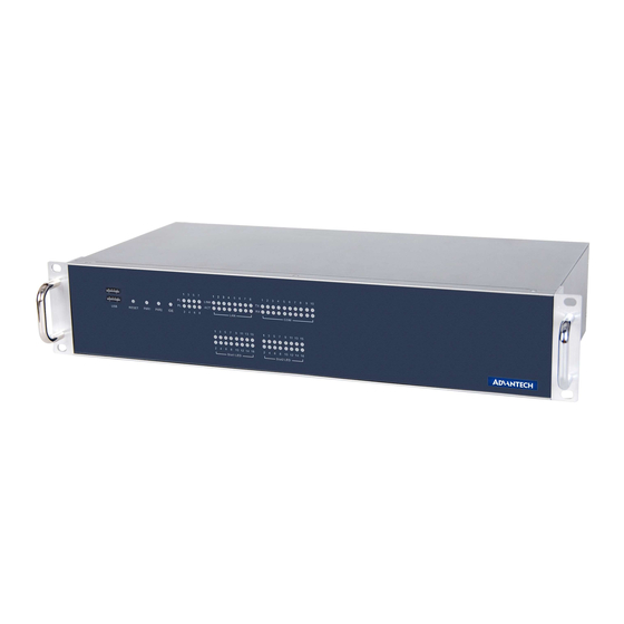
Overview The following figures show the indicators and connectors on the ECU-4784 Series. The following sections give you detailed information about the functions of each peripheral. 2.1.1 ECU-4784 LED and Interface Position Figure 2.1 ECU-4784 Front Panel Figure 2.2 ECU-4784 Rear Panel... -
Page 21: Led Indicators
LED Indicators 2.2.1 ECU-4784 LED Indicators The LEDs in the front panel can be divided into 3 groups. 2.2.1.1 System Status Indicators Table 2.1: Definition of System Status Indicators Item Status Description Green System power1 is on PWR1 System power1 is off Green System power2 is on PWR2... - Page 22 2.2.1.2 LAN Status Indicators ECU-4784 LAN LED status Indicators Table 2.2: Definition of LAN Status Indicators Item Status Description Green 1Gbps network link LAN/LINK Orange 100Mbps network link (Port 1~8) 10Mbps network link or invalid network link Green Ethernet date being received/transmitted LAN/ACT (Port 1~8) No Ethernet data being received/transmitted...
- Page 23 There are up to 8 LEDs (LED0~LED7) and could control and monitor the status (On/ Off), The Advantech programmable LED driver provides examples on how to use the ECU-4784's programmable LED and offers reference for users to develop their own applications.
-
Page 24: Power Input
Power Input The ECU-4784 Series products support single power input AC or DC. Table 2.5: Power Input Item AC/DC Volt. Range Power Rating Connector Type 100-240 V 0.7 A 50-60 Hz 3Pin Screw Terminal PWR1 100-240 V 0.7 A 3Pin Screw Terminal The function of each part is described as below: Figure 2.3 Power1 Input Location... -
Page 25: Rs-232 Interface (Com1, Com2)
Figure 2.4 AT X/AT Power Mode Select Location (CN67) RS-232 Interface (COM1, COM2) The ECU-4784 Series offer two standard RS-232 serial communication interface ports: COM1 and COM2. Please refer to A.1 for pin assignments. It can not support the IRQ, I/O address is the same with super I/O. -
Page 26: Rs-232/422/485 Interface (Com3~Com10)
RS-232/422/485 Interface (COM3~COM10) The ECU-4784 Series offers 8 ports RS-232/422/485 serial communication interface ports: COM3 to COM10. Please refer to Appendix A.2 for their pin assignments. Users can select each port for RS-232 or RS-422/485 through different connections. Table 2.8: Jumper Setting of RS-232/RS-422/RS-485 Selection (For... - Page 27 Figure 2.5 COM3~10 Port Related Jumper Locations (CN16-CN23) Figure 2.6 COM3~10 Port Related Jumper Locations (SW2) ECU-4784 User Manual...
-
Page 28: Uart Chips
2.5.3 Automatic Data Flow Control Function for RS-485 In RS-485 mode, the ECU-4784 Series automatically detect the direction of incoming data. So no handshake signal (e.g. RTS signal) is necessary. This lets you conve- niently build an RS-485 network with just two wires. - Page 29 Table 2.12: Mapping Table of Jumper for COM (3~10) Port COM Port Jumper for Terminal Resistor COM3 CN27 COM4 CN28 COM5 CN29 COM6 CN30 COM7 CN31 COM8 CN32 COM9 CN33 COM10 CN34 CN34/33/31/29/27/32/30/28 Figure 2.7 COM3~10 Port Related Jumper Locations (CN27-CN34) ECU-4784 User Manual...
-
Page 30: Relay Output For Event
Figure 2.8 Relay Output Connections Figure 2.9 Wiring Diagram of the Relay out The ECU-4784 Series provides a relay out alarm function, which is convenient for the user to control the relay out alarm using the API. For the detailed explanation of the relay out API, please refer to: C:\Program Files\Advantech\AdvRelay\Examples\VC++\RelayTool"... -
Page 31: Lan: Ethernet Connector
1 USB 2.0 port inside the chassis for a USB dongle key. DVI and VGA Display The ECU-4784 Series equipped with DVI-I and DVI-D, the resolution is up to 1920 x 1200@60Hz. Please refer to the specification table in Chapter 1 for further informa- tion. -
Page 32: Expansion Pci & Pcie
AMT can be managed remotely, regardless of whether they are powered up or whether they have a functioning OS. The ECU-4784 Series supports AMT. You can see the step-by-step guide on how to enable AMT function in the help guide. -
Page 33: Tpm
2.14 The ECU-4784 Series support Trusted Platform Module (TPM) technology, TPM is designed to provide hardware-based, security-related functions. A TPM is a micro- chip designed to provide basic security-related functions, primarily involving encryp- tion keys. The TPM is usually installed on the motherboard of a computer, and com- municates with the rest of the system using a hardware bus. - Page 34 ECU-4784 User Manual...
-
Page 35: Initial Setup
Chapter Initial Setup Sections include: Configuration Installing a CompactFlash Card Installing a USB Dongle Installing Hard Disk Installation on Rack BIOS Setup and System Assign- ments... -
Page 36: Configuration
Configuration To open the ECU-4784 Series product chassis, follow the steps below: Remove all power and signal connections. Remove the screws as shown below. Figure 3.1 ECU-4784 Screw Location Remove the chassis’s top cover: Figure 3.2 ECU-4784 Removing the Top Cover... - Page 37 Open the chassis’s top cover, Users can set the COM port terminal resistor by jumper according to demand. For more detailed information users should refer to chapter 2.5. Figure 3.3 ECU-4784 Open the Chassis Top Cover ECU-4784 User Manual...
-
Page 38: Installing A M.2 Pcie Card
Installing a M.2 PCIE Card The ECU-4784 Series provides 1 x M.2 PCIE card slot to install the cards: Unscrew the 2 screws and remove the M.2 PCIE card back plate. Figure 3.4 M.2 PCIE Card Slot Location Insert the card at location (CN74) shown below. -
Page 39: Installing A Usb Dongle
Installing a USB Dongle The ECU-4784 Series provides a clamp for the USB dongle which can be installed inside the chassis. Follow these steps to install the USB dongle and clamp: Refer to section 3.1 to open the chassis. Figure 3.6 Open the Chassis Plug the USB Dongle in the upper port of CN14, note that the lower port is a dummy port. - Page 40 CN37 Figure 3.8 CN37 Location of the Internal USB Port Adjust the position of the kit to fasten the USB dongle, then screw to fix the kit. ECU-4784 User Manual...
-
Page 41: Installing A Hard Disk
Installing a Hard Disk Follow the steps below to install a HDD: To install a HDD and HDD bracket (in the accessory). Figure 3.9 SATA HDD Fixed Diagram ECU-4784 User Manual... - Page 42 Unscrew the 2 screws and remove the HDD back plate. Figure 3.10 HDD Back Plate Location and SATA HDD Installation Diagram According to the schematic drawing, the HDD is directly installed on the device through the DIN-Rails (ECU-4784 supports up to 3 x HDD the 3rd HDD location is on top as show below).
- Page 43 ECU-4784 series contains SATA signal and power cable for three SATA HDD in the chassis. The locations of the connectors are shown below, SATA signal con- nector and SATA power connectors are located on CN41/43/CN75. Figure 3.11 2 x SATA Signal and Power Connector Locations (CN41/43/75)
-
Page 44: Rack Installation
5mm. (2) There is no limit on the size of the hole on the bottom. The ECU-4784 Series has aluminum fins on the top of the unit as heat-sink. It can generate natural convection for better heat transmission. To have optimal thermal performance, leave 2U (88.9 mm) space above the unit. -
Page 45: Installing The Expansion Card
Installing the Expansion Card The ECU-4784 series provides two expansion slots for expansion card installation. Unscrew the 2 screws and remove the two expansion back plate. Plug in the PCI Card or PCIE card through the DIN-Rails. ECU-4784 User Manual... -
Page 46: Bios Setup And System Assignments
Then secure the expansion cards using the previously removed screws. BIOS Setup and System Assignments The ECU-4784 with Intel 6th & 8th Generation Processor adopts Advantech's CPU module, and ECU-4784 with Intel 6th & 8th Generation Processor adopts Advant- ech's CPU module. Further information about the SOM module, can be found in the SOM user manual. -
Page 47: Appendix A Pin Assignments
Appendix Pin Assignments... -
Page 48: Rs-232 Serial Ports (Com1 ~ Com2)
RS-232 Serial Ports (COM1 ~ COM2) Table A.1: COM (1~2) Port Pin Definitions Pins RS-232 ECU-4784 User Manual... -
Page 49: Rs-232/422/485 Serial Ports (Com3 ~ Com10)
RS-232/422/485 Serial Ports (COM3 ~ COM10) Table A.2: RS-232/422/485 Serial Ports (COM3 ~ 10) Pins RS-232 RS-422 RS-485 Data+ Data- Table A.3: Relay Output Connectors Pin Definitions Pins Definitions Normal OPEN COMMON Reference Normal CLOSE Power Failure and Relay out Function ECU-4784 User Manual... -
Page 50: Relay Output Connectors Pin Assignments
Relay Output Connectors Pin Assignments USB Connectors (USB1 ~ USB5) Table A.4: USB Connector Pin Assignments Signal Cable Color DATA- White DATA+ Green Black ECU-4784 User Manual... -
Page 51: Lan Connectors (Lan1~Lan8)
LAN Connectors (LAN1~LAN8) Table A.5: LAN Connector Pin Assignments Assignment Description Transmit + Transmit - RD + Receive + not used not used RD - Receive - not used not used VGA Display Connector Table A.6: VGA Adaptor Cable Pin Assignments Signal GREEN BLUE... -
Page 52: Dvi Display Connector
DVI Display Connector Table A.7: DVI Adaptor Cable Pin Assignments Signal TMDS_C2# TMDS_C2 CRT_DDC_CLK CRT_DDC_DATA MDVI_CLK MDVI_DATA VGAVSY TMDS_C1# TMDS_C1 VCC_DVI VGA Detect HP_DET TMDS_C0# TMDS_C0 TMDS_CK# TMDS_CK VGAR VGAG VGAB VGAHSY ECU-4784 User Manual... -
Page 53: Power Pin Assignments
POWER Pin Assignments Table A.8: AC/DC Power Input PIN Definition Pins Screen Printing Function Description L/V+ PWR1 AC/DC power input PIN N/V- PWR1 AC/DC power input PIN Note! If the customer wants to use a dual power supply, refer to Table2.1 for power input specifications. - Page 54 ECU-4784 User Manual...
-
Page 55: Appendix B Watchdog Timer Programming
Appendix Watchdog Timer Programming... -
Page 56: Watchdog Timer Programming
Watchdog Timer Programming -------------------------------------------------------------- --------------------- Enter the extended function mode, interruptible double-write -------------------------------------------------------------- --------------------- MOV DX,2EH MOV AL,87H OUT DX,AL OUT DX,AL -------------------------------------------------------------- --------------- Configured logical device 8, configuration register CRF6 -------------------------------------------------------------- --------------- MOV DX,2EH MOV AL,2BH OUT DX,AL MOV DX,2FH IN AL,DX AND AL.OEFH;... - Page 57 Appendix BIOS Setup...
- Page 58 BIOS Setup and System Assignments AMIBIOS has been integrated into many motherboards for over a decade. With the AMIBIOS Setup program, users can modify BIOS settings and control the various system features. This chapter describes the basic navigation of the BIOS setup screens.
- Page 59 C.2.1 Main Setup When users first enter the BIOS Setup Utility, users will enter the Main setup screen. Users can always return to the Main setup screen by selecting the Main tab. There are two Main Setup options. They are described in this section. The Main BIOS Setup screen is shown below.
- Page 60 C.2.2 Advanced BIOS Features Setup Select the Advanced tab from the ECU-4784 setup screen to enter the Advanced BIOS Setup screen. Users can select any item in the left frame of the screen, such as CPU Configuration, to go to the sub menu for that item. Users can display an Advanced BIOS Setup option by highlighting it using the <Arrow>...
- Page 61 C.2.2.1 ACPI Settings Figure C.4 ACPI Setting Enable ACPI Auto Configuration This item allows users to enable or disable BIOS ACPI auto configuration. Enable Hibernation This item allows users to enable or disable hibernation. ACPI Sleep State This item allows users to set the ACPI sleep state.
- Page 62 C.2.2.2 Trusted Computing Figure C.5 Trusted Computing Security Device Support This item allows users to enable or disable BIOS support for security device support, and the OS will not show the Security Device. TCG EFI Protocol and INT1A interface will not be available. ECU-4784 User Manual...
- Page 63 C.2.2.3 CPU Configuration Figure C.6 CPU Configuration Hyper-threading Enable for Windows XP and Linux (OS optimized for Hyper-Threading Technol- ogy) and Disable for other OS (OS not optimized for Hyper-Threading Technol- ogy) and Disable for other OS (OS not optimized for Hyper-Threading Technology).
- Page 64 CPU AES This item allows users to enable or disable CPU Advanced Encryption Standard instructions. Boot performance mode This Item allows users to select the performance state that the BIOS will set before OS handoff. EIST This item allows users to enable or disable Intel SpeedStep. Turbo Mode ...
- Page 65 SATA Controller(s) This item allows users to enable or disable SATA devices. SATA Mode Selection This item allows users to select SATA mode selection. (Determines how SATA controller(s) operate) Aggressive LPM Support This item allows users to enable or disable PCH to aggressively enter link power state.
- Page 66 C.2.2.5 PCH-FW Configuration Figure C.8 PCH-FW Configuration MDES BIOS Status Code This item allows users to enable or disable MDES BIOS status code. TPM Device Selection This item allows users to enable or disable TPM Device Selection. (PTT or dTPM.
- Page 67 Firmware Update Configuration Figure C.9 Firmware Update Configuration ME FW Image Re-Flash This item allows users to enable or disable ME FW Image Re-Flash function. ECU-4784 User Manual...
- Page 68 C.2.2.6 AMT Configuration Figure C.10 AMT Configuration Intel AMT This item allows users to enable or disable Intel AMT (Active Management Technology) BIOS Extension. Note! iAMT H/W is always enabled. This option just controls the BIOS exten- sion execution. If enabled, this requires additional firmware in the SPI device.
- Page 69 Activate Remote Assistance Process This item allows users to enable or disable Activate Remote Assistance Pro- cess.To Trigger CIRA boot. USB Configure This item allows users to enable or disable USB Configure function. PET Progress This item allows users to enable or disable PET Events progress to receive PET events or not.
- Page 70 This is a workaround for OS without EHCI hand-off support. The EHCI owner- ship change should be claimed by EHCI driver. USB Mass Storage Driver Support This item allows users to enable or disable USB Mass Storage Driver Support. USB transfer time-out ...
- Page 71 Parallel Port Configuration This item allows users to set Parameters of Parallel Port (LPT/LPTE). Hardware Monitor This item allows user to change monitor hardware status. COM Port 1 Configuration Figure C.13 COM Port 1 Configuration COM Port 1 ...
- Page 72 COM Port 2 Configuration Figure C.14 COM Port 2 Configuration COM Port 2 This item allows users to enable or disable the COM Port. Change settings This item allows users to select an optimal setting for the Super IO device. Device Mode ...
- Page 73 Parallel Port Configuration Figure C.15 Parallel Port Configuration Parallel Port This item allows users to enable or disable Parallel Port (LPT/LPTE). Change settings This item allows users to select an optimal setting for the Super IO device. Device Mode ...
- Page 74 Hardware Monitor Figure C.16 PC Hardware Monitor This item monitors hardware status. C.2.2.9 iManager Configuration Figure C.17 iManager Configuration ECU-4784 User Manual...
- Page 75 CPU Shutdown Temperature This item allows users to select CPU Shutdown Temperature. iManager Smart Fan - COM Module This item allows users to enable or disable iManager Smart Fan - COM Module. To control iManager Smart FAN function. iManager Smart Fan - Carrier Board ...
- Page 76 COM Port 4 Configuration Figure C.19 COM Port 4 Configuration COM Port 4 This item allows users to enable or disable a COM Port. Change settings This item allows users to select an optimal setting for the Super IO device. Device Mode ...
- Page 77 Hardware Monitor Figure C.20 Hardware Monitor This item monitor hardware status. ECU-4784 User Manual...
- Page 78 C.2.2.10Serial Port Console Redirection Figure C.21 Serial Port Console Redirection COM1 Console Redirection This item allows users to enable or disable Console Redirection. COM2 Console Redirection This item allows users to enable or disable Console Redirection. COM3 Console Redirection ...
- Page 79 C.2.3 Chipset Select the Chipset tab from the ECU-4784 setup screen to enter the Chipset BIOS Setup screen. You can display a Chipset BIOS Setup option by highlighting it using the <Arrow> keys. All Plug and Play BIOS Setup options are described in this sec- tion.
- Page 80 C.2.3.1 PCH-IO Configuration Figure C.23 PCH-IO Configuration PCI Express Configuration This item allows users to change PCI Express Configuration settings. USB Configuration This item allows users to change USB Configuration settings. PCH LAN Controller This item allows users to enable or disable onboard NIC. Wake on LAN ...
- Page 81 C.2.3.1.1PCI Express Configuration Figure C.24 PCI Express Configuration PCI Express Clock Gating This item allows users to enable or disable PCI Express Clock Gating for each root port. DMI Link ASPM Control This item allows users to enable or disable DMI Link ASPM Control. The Control of Active State Power Management on both NB side and SB side of the DMI Link.
- Page 82 PCI Express Root Port 1 Configuration Figure C.25 PCI Express Root Port 1 Configuration PCI Express Root Port 1 This item allows users to enable or disable PCI Express Root Port. ASPM Support This item allows users to set the ASPM level. Force L0s- Force all links to L0s state.
- Page 83 PCI Express Root Port 2 Configuration Figure C.26 PCI Express Root Port 2 Configuration PCI Express Root Port 2 This item allows users to enable or disable PCI Express Root Port. ASPM Support This item allows users to set the ASPM level. Force L0s- Force all links to L0s state.
- Page 84 PCI Express Root Port 3 Configuration Figure C.27 PCI Express Root Port 3 Configuration PCI Express Root Port 3 This item allows users to enable or disable PCI Express Root Port. ASPM Support This item allows users to change L1 Substates settings. Hot Plug ...
- Page 85 PCI Express Root Port 4 Configuration Figure C.28 PCI Express Root Port 4 Configuration PCI Express Root Port 4 This item allows users to enable or disable PCI Express Root Port. ASPM Support This item allows users to change L1 Substates settings. Hot Plug ...
- Page 86 C.2.3.2 System Agent (SA) Configuration Figure C.29 System Agent (SA) Configuration VT-D This item allows users to enable or disable VT-d function. Graphics Configuration This item allows users to change graphics setting. Memory Configuration This item allows users to change memory configuration parameters. ECU-4784 User Manual...
- Page 87 C.2.3.2.1 Graphics Configuration Figure C.30 Graphics Configuration Primary Display This item allows users to select which of IGFX/PEG/PCI Graphics device should be Primary display or select SG for Switchable Gfx. Internal Graphics This item keeps IGD enabled based on the setup options. Aperture Size ...
- Page 88 LCD Control Figure C.31 LCD Control This item allows users to perform LCD control. ECU-4784 User Manual...
- Page 89 C.2.3.2.2Memory Configuration Figure C.32 Memory Configuration Memory Information This item shows memory configuration parameters. ECU-4784 User Manual...
- Page 90 C.2.4 Boot Figure C.33 Boot Setup Utility Setup Prompt Timeout This item allows users to select the number of seconds to wait for setup activa- tion key. Bootup NumLock State Select the keyboard NumLock state. Quiet Boot This item allows users to enable or disable Quiet Boot option.
- Page 91 C.2.5 Security Setup Figure C.34 Security Setup All Security Setup options, such as password selection is described in this section. To access the sub menu for the following items, select the item and press <Enter>: Change Administrator/User Password Select this option and press <ENTER> to access the sub menu, and then type in the password.
- Page 92 C.2.6 Save & Exit Figure C.35 Save & Exit Save Changes and Exit When users have completed system configuration, select this option to save changes, exit BIOS setup menu and reboot the computer if necessary to take effect all system configuration parameters. Discard Changes and Exit ...
- Page 93 ular, do not use the Optimal Defaults if the users computer is experiencing system configuration problems. Save User Defaults When users have completed system configuration, select this option to save changes as user defaults without exit BIOS setup menu. Restore User Defaults ...
- Page 94 No part of this publication may be reproduced in any form or by any means, such as electronically, by photocopying, recording, or otherwise, without prior written permission from the publisher. All brand and product names are trademarks or registered trademarks of their respective companies. © Advantech Co., Ltd. 2021...
Need help?
Do you have a question about the ECU-4784 Series and is the answer not in the manual?
Questions and answers