
Related Manuals for Transmitter Solutions Dolphin DOLXP1KB


Summary of Contents for Transmitter Solutions Dolphin DOLXP1KB
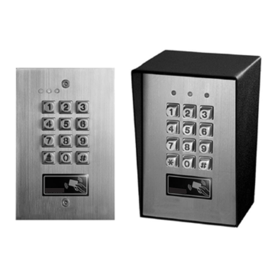
- Page 1 VANDAL RESISTANT BACK-LIT WEATHERPROOF ACCESS CONTROL KEY AND CARD READER WITH WIEGAND OUTPUT & APO DATA I/O Dolphin Keypad DOLXP1KB Programming & Installation Manual FOR ELECTRIC LOCK, INTER-LOCK AND SECURITY SYSTEM INSTALLATIONS...
-
Page 2: Table Of Contents
TABLE OF CONTENTS ..................4 INTRODUCTION . - Page 3 ......3 0 THE Transmitter Solutions DATA I/O PORT -- FOR SETTING UP A SPLIT-DECODED KEYPAD .
-
Page 4: Introduction
EM card reader in one unit. It can work independently as a stand alone keypad or works together with an optional “Transmitter Solutions controller” to form a high security split- decoded keypad system. It is also a card reader providing 34 bits Wiegand data output from the entry of an PIN/code. -
Page 5: Specifications
SPECIFICATIONS Operating Voltage: 12V-24V DC, Auto adjusting Operating Current: 75mA (quiescent) to 145mA (three relays active) Operation Temperature: -4 F to 158 F Environmental Humidity: 5-95% relative humidity non-condensing Working Environment & Ingress Protection: All weather, IP-66 Number of Users: Output 1 –... -
Page 6: Installation
INSTALLATION DOLXP1KB -- Surface Mount Version Steel Box Plastic inner box Faceplate PRECAUTIONS Prevent Interference: The EM Card reader is working at the frequency of 125 KHz. Installation precaustions are necessary. i) Make sure the location for the installation has no strong low frequency electro-magnetic wave signals. Especially in the range of 100-200 KHz. -
Page 7: Connection Terminals
CONNECTION TERMINALS WIEGAND & DATA I/ O HARNESS BACK-LIT JUMPER K OR A JUMPER CONNECTION TERMINALS 1 - 2 : 12-24V DC (Power Input Terminal) Connect to 12-24V DC power supply. The (-) supply and the (-) GND are the common grounding points of the system. The system accepts full input voltage range with no jumper selection. - Page 8 notification at remote location. 13 : “K” OR “A” O/P (Keypad Active Output or Alarm Output) An NPN transistor open collector output with the maximum power rating of 24VDC/100mA sink. It is equivalent to an 14 : DU OUT (Duress Output) N.O.
-
Page 9: The On-Board Led Indicators
An inter-lock system needs two keypads and two door position sensing switches for the two doors. 19 - 20 : TAMPER N.C. (Tamper Switch Normally Closed Contact) A normally closed dry contact while the keypad is secured on its box. It is open while keypad is separated from the box. -
Page 10: Feature Programming & Operation Instructions
FEATURE PROGRAMMING & OPERATION INSTRUCTIONS SET SYSTEM INTO PROGRAMMING MODE WITH THE MASTER CODE IMPORTANT NOTE: 1) DO NOT TURN OFF POWER while the keypad is in Programming Mode. Otherwise, it may cause data lost/error to the programmed features in the memory. 2) The keypad beeps after power up. -
Page 11: The Default Values Of The Keypad
REFRESH THE SYSTEM WITH THE “REFRESHING CODE” --- 9 9 9 9 The system can be refreshed to clear all the old data stored and back to its ex-factory default values. IMPORTANT NOTE: Make sure that you really want to clear ALL the OLD data before entering of the Refreshing Code. The keypad will be back with its default values like a new unit. -
Page 12: Keypad Programming Make Simple - For General Users
KEYPAD PROGRAMMING MAKE SIMPLE – For General Users This is a multi purpose keypad. It has many functions for user’s selection. For those general users taking the keypad for door strike only, most of the features can be kept in their Default values. Only the User PINs and a private Master Code are necessary to program for the system. - Page 13 (e) 6123 = The User PIN to be used with the EM Card. 6123 is an User PIN for example here only. 6) Record an “EM Card + Commom User Code” to Operate The Output 1 for Door Open R E A D (a) 10 = Programming Location for Output 1 (b) 4 = Programming option for EM Card + Common User Code (c) 004 = One of the 1,000 User IDs for the User PIN/Card from 000-999...
-
Page 14: Feature Programming -- Key In And Store The Desired Values
FEATURE PROGRAMMING -- KEY IN AND STORE THE DESIRED VALUES The feature values can be set and stored into the system one by one with the desired Programming Locations. Programming can be made continuously and it is not necessary to be in sequence order. Just go to the desired programming location and key in the value for the desired feature. -
Page 15: Record A Master Code
Example: User Name Location Function Code User ID PIN/Code Card # Remark RECORD A MASTER CODE (Location 01) LOCATION MASTER CODE VALIDATION 4 to 8 Digits MASTER CODE Master Code is the authorization code for setting the system to programming mode. It is NOT an User Code operating of the output relays. -
Page 16: Operation And Functions Of The Super User Pin
OPERATION AND FUNCTIONS OF THE SUPER USER PIN 1) Operate Output 1, 2, and 3 The operation of the Super User PIN is just like a normal User PIN. Simply key-in the PIN with a specific output number for the desired Output. The Super User PIN can also be used to reset an operating output timer instantly. ---------- Output 1 Activates or Output 1 Resets SUPER USER PIN SUPER USER PIN... - Page 17 RECORD-DELETE USER PINS OR CARDS FOR OUTPUT 1, 2, & 3 (Locations 10, 20 & 30) Total of 1,200 User PINs and/or Cards are available for the 3 user groups to control the 3 outputs. 1) 1,000 ---- for Output 1 (Group 1) 2) 100 ------ for Output 2 (Group 2) 3) 100 ------ for Output 3 (Group 3) The Private User PINs and Cards in the 3 user groups...
-
Page 18: Examples - Programming And Operation
EXAMPLES – PROGRAMMING AND OPERATION 1) Example 1 -- EM Card Only : i) Programming : R e a d (a) The card is programmed for operating of the Output 1 (b) The operation is EM Card only (c) Take ID number 001 in Group 1 to store the card, which is one of the IDs in 000-999 ii) Operation : (while the system is back to operation mode) R e a d a)Put the EM card close to the reader. - Page 19 4) Example 4 -- EM Card + Common User PIN : i) Programming : 10 4 R e a d (a) The card is programmed for operating of the Output 1 (b) The operation is “EM Card + Common User PIN” (c) Take ID number 003 in Group 1 to store the card, which is one of the IDs in 000-999 (d) Put the card close to the reader.
-
Page 20: Visitor Codes (For Output 1 Only)
VISITOR CODES (FOR OUTPUT 1 ONLY) (Location 40) The Visitor Codes are the temporary user codes for operating of the Output 1 (mainly for door strike in access control). They can be programmed as “One Time Codes” or “Codes with Time Limit”. The Visitor Codes will be cleared automatically after use if they are one time codes, or, when the allowed time expires. -
Page 21: Duress Codes (For Outputs 1, 2 & 3)
Example 1: Set a “One Time Visitor Code” with the number of “1 2 6 8” for the Output 1 40 01 00 1268 # (a) Visitor Code Programming, (b) The Visitor ID, (c) An One Time Code, (d) The Visitor Code, (e) Entry Confirmation Example 2: Set a “Visitor Code”... -
Page 22: The Operation And Function Of The Duress Code
EXAMPLES: Example 1: Set a “Duress Code” with the number of “3 3 6 9” for Output 1 41 01 3369 # (a) Duress Code Programming for Output 1, (b) Duress Code ID, (c) The Duress Code, (e) Entry Confirmation Example 2: Set a “Duress Code”... -
Page 23: Personal Safety And System Lock-Out
a) Put the EM card close to the reader. One-beep confirms the reading and 30 seconds waiting time is given for the entry of the Duress Code, the Amber LED keeps flashing. b) Key in the Duress Codes 3 3 6 9 for operating the Output 1 c) Confirm it with the # key. -
Page 24: User Pin Entry Mode
USER PIN ENTRY MODE – Auto or Manual (Location 70) LOCATION ENTRY MODES VALIDATION USER PIN ENTRY MODES Two modes 1 and 2 are available for User PIN entry options. The EM Card is always in Auto Entry Mode and is not affected by the selection here. -
Page 25: Status Led Flashing On-Off During Standby
STATUS LED FLASHING ON-OFF DURING STANDBY (Location 73) LOCATION FUNCTION MODES VALIDATION STANDBY FLASHING ON-OFF Some people find the flashing light of the status LED (the amber LED) is annoying during the keypad is on standby, especially at the night time. The standby flashing can be ON-OFF with the setting here. --- Standby Flashing ON -- (Default) The Status LED gives Standby Flashing all the time during the keypad is on standby. -
Page 26: Intelligent Egress Button - An Unique Feature Of A Contemporary Keypad
INTELLIGENT EGRESS BUTTON – AN UNIQUE FEATURE OF A CONTEMPORARY KEYPAD Most of the keypads for access control are just for controlling of “Going In” from outside. It is not enough for today’s access control systems. In fact, controlling of “Going Out” is also very important in many public passage areas. They are not allowed to use locks or digital keypads for stopping of “Going Out”... -
Page 27: Egress Delay , Warning And Alarm
EGRESS DELAY , WARNING AND ALARM (Location 90) LOCATION FUNCTION MODES DELAY TIME VALIDATION CONFIGURATIONS OF THE EGRESS WARNING AND ALARM Key in the number to enable 1 of the 6 configurations described below: --- Momentary Contact Mode without Warning -- (Default) •... -
Page 28: Door Opening Alarm & Timer
EXAMPLES: Example 1: Set Egress Button in Momentary contact 5 seconds with delay & warning beep 90 2 5 # (a) Egress function programming, (b) Momentary contact with warning, (c) Delay time of 5 seconds to release door, (d) Entry confirmation Example 2: Set Egress Button in Holding contact of 10 seconds with warning beep 90 5 10 # (a) Egress function programming, (b) Holding contact mode with warning, (c) Holding time of 10 seconds to release... -
Page 29: The Wire Harness For "Wiegand Data Output" & "Transmitter Solutions Data I
The keypad unit comes with two sets of interface wires from the wire harness. The Wires 1-4 are the Wiegand interface wires. The Wire 6 is the Data Input/Output wire for the connection with the optional Transmitter Solutions’s Digital Keypad Access Controller, for high security Split-decoded operation. The Wire 5 is the Common Grounding point of these signal wires. -
Page 30: The Operation Modes And The Wiegand Output
THE OPERATION MODES AND THE WIEGAND OUTPUT (Location 94) Four operation modes are available for the selection. The codes are 0, 1, 2 and 3. LOCATION OPERATION MODE VALIDATION WIEGAND OUTPUT AT KEYPAD OPERATION MODE 0 --- Stand Alone Keypad Mode -- (Default) The system provides full functions to operate its outputs and at the same time provides Wiegand Data Output for all VALID Cards and User PINs including the Duress Codes and Visitor Codes. -
Page 31: Timing & Electrical Manner Of The Wiegand Data Output
TIMING & ELECTRICAL MANNER OF THE WIEGAND DATA OUTPUT The Wiegand is a commonly used interface between readers and control panels used in access control security and other related industries. The majority of cards in access control systems use a Wiegand interface to transmit data read from a card to a control panel. - Page 32 THE 26 BIT WIEGAND DATA OUTPUT FROM THE EM CARDS Even parity the trailing parity bit is an Odd parity bit from the last 12 bits. The data transmitted is in Binary codes for the Card reading. Example 1: Wiegand Output of Reading An EM Card Each EM card or Keyfob is marked with an unique ID in Decimal Digits that is the code read by the reader.
-
Page 33: Example: Wiegand Output From Pin / Code Entry
THE 34 BIT WIEGAND DATA OUTPUT FROM THE ENTRY OF USER PINS Wiegand is a commonly used interface between keypad with user PINs and control panels used in access control. The keypad unit accepts User PINs up to 8 digits maximum in decimal numbers. The Wiegand data protocol has been made to 34 bits to accommodate the maximum PIN length without causing code error (26 bits Wiegand data causes error to number 16,777,215 or any number above 16,777,215). -
Page 34: The Transmitter Solutions Data I/O Port -- For Setting Up A Split-Decoded Keypad
The keypad unit comes with a data I/O (data input and output) port for the connection with the Transmitter Solutions’s Access Controller for Split-decoded operation to up-grade its security level. Once the keypad unit is connected with the controller, all the commands from it will be faithfully decoded by the decoder. -
Page 35: Programming Summary Chart
PROGRAMMING SUMMARY CHART ENTRY LIMITS & CODE FACTORY LOCATION CODE ENTRY FUNCTION OPTIONS DEFAULT Master Code 4-8 Digits MASTER CODE # Super User PIN 4-8 Digits SUPER USER PIN # Common User PIN for O/P 1 COMMON USER PIN 1 # Common User PIN for O/P 2 4-8 Digits COMMON USER PIN 2 #... - Page 36 FUNCTION MODE / TIME: Mode = 0, Door Forced Open Warning 0---OFF Door Forced FUNCTION / TIME & Time 1-999 Seconds Open Warning OFF Mode = 0, Propped-up Warning & Time FUNCTION / TIME Propped-up Warning OFF CODE 1 - FUNCTION MODE: 1---Momentary, No warning 2---Momentary, with warning 3---Momentary, with warning +...
-
Page 37: Application Examples
APPLICATION EXAMPLES 1) BASIC WIRINGS OF A STAND ALONE DOOR LOCK NOTE: Connect the 1N4004 as close as possible to the lock in parallel with the lock power terminals of the lock to absorb the back EMF to prevent it from damaging the keypad. The 1N4004 is not required if the electric lock is AC operated. -
Page 38: Basic Wirings Of A Stand Alone Door Lock With Inhibit Authorization Code
2) BASIC WIRINGS OF A STAND ALONE DOOR LOCK WITH INHIBIT AUTHORIZATION CODE DOLXP1KB Use output 3 as authorization control. The owner may key in the user code 3 to stop the operation of the electric lock in the night time or after office hour to prevent unauthorized access. Set output 3 in Start / Stop mode (Programming Location 53 Output Mode =0) for ON-OFF control. -
Page 39: Basic Wirings Of An Inter-Lock System Using Two Keypads
3) BASIC WIRINGS OF AN INTER-LOCK SYSTEM USING TWO KEYPADS An inter-lock system needs two door controllers. This application example uses two keypads with simple cross wire connection on their "Output 1 Inhibit" and "Inter-lock Control Output" terminals. It is necessary to link up the "(-) GND"... -
Page 40: Application Hints For The Auxiliary Terminals
APPLICATION HINTS FOR THE AUXILIARY TERMINALS (A) TAMPER N.C. The tamper switch is Normally Closed while the keypad is secured on gang box. It is open when the keypad is removed from the gang box. To prevent sabotage, connect these terminals in series with a 24 hour N.C. protection zone of an alarm system if required. - Page 41 (F) OUTPUT 2 ( i ) Shunting an N.C. Zone Use the Normally Open (N.O.) output contact to shunt a Normally Closed (N.C.) protection zone of an alarm system. Set output contact to Start / Stop Mode (Programming Option 52, Output Mode=0). ( ii ) Alarm System Arm-Disarm Control Use the (N.O.) or (N.C.) output contact to make arm-disarm control of an alarm system.
-
Page 42: Appendix
APPENDIX DRY CONTACT A dry contact means that no electricity is connected to it. It is prepared for free connections. The Relay Output contacts provided in this keypad system are dry contacts. N.C. Normally Closed, the contact is closed circuit at normal status. It is open circuit when active. N.O.
Need help?
Do you have a question about the Dolphin DOLXP1KB and is the answer not in the manual?
Questions and answers