kozy heat 55801 Duluth Installation & Operating Manual
Free-standing direct vent
fireplace
Hide thumbs
Also See for 55801 Duluth:
- Installation and operation manual (37 pages) ,
- Installation and operation manual (33 pages) ,
- Installation & operating manual (28 pages)
Table of Contents
Advertisement
Quick Links
MODEL #55801 'Duluth'
Free-Standing Direct Vent
WARNING: If the information in these instructions
is not followed exactly, a fire or explosion may
result, causing property damage, personal injury
.
or loss of life
Do not store or use gasoline or other
S
flammable vapors and liquids in the vicinity of
this or any other appliance.
WHAT TO DO IF YOU SMELL GAS:
Do not try to light any appliance.
‚
‚
Do not touch electrical switches; do not use
the phone in your building.
Immediately call your gas supplier from a
‚
neighbor's phone. Follow your gas supplier's
instructions.
If you cannot reach your gas supplier, call the
‚
fire department.
Installation and service must be performed by
S
a qualified installer, service agency or the gas
supplier.
This appliance may be installed in an aftermarket
INSTALLATION & OPERATING MANUAL
Fireplace
U.S. Patent Numbers 5,931,154 & 6,004,493
permanently located, manufactured home or mobile
home, where not prohibited by local codes. This
appliance is only for use with the type(s) of gas
indicated on the rating plate. This appliance is not
convertible for use with other gases, unless a
certified kit is used.
IMPORTANT:
READ
INSTRUCTIONS
INSTALLATION. FAILURE TO INSTALL THIS FIREPLACE
CORRECTLY CAN CAUSE SERIOUS STRUCTURAL AND
FIRE HAZARDS AND MAY VOID YOUR WARRANTY.
www.kozyheat.com
CAREFULLY
BEFORE
July 2006
Advertisement
Table of Contents

Related Manuals for kozy heat 55801 Duluth


Summary of Contents for kozy heat 55801 Duluth
- Page 1 INSTALLATION & OPERATING MANUAL MODEL #55801 ‘Duluth’ Free-Standing Direct Vent Fireplace U.S. Patent Numbers 5,931,154 & 6,004,493 permanently located, manufactured home or mobile home, where not prohibited by local codes. This WARNING: If the information in these instructions appliance is only for use with the type(s) of gas is not followed exactly, a fire or explosion may indicated on the rating plate.
-
Page 2: Table Of Contents
INDEX DESCRIPTION PAGE Safety Requirements / Specifications ..........Front cover, 1-2 Clearances . - Page 3 MODEL: #55801 ‘DULUTH’ FREESTANDING DIRECT VENT FIREPLACE INSTALLATION & OPERATING INSTRUCTIONS IMPORTANT: READ THIS MANUAL BEFORE INSTALLING AND USING THIS FIREPLACE. This fireplace has been tested to and complies with ANSI Z21.88 CSA 2.33-M2002 “VENTED GAS FIREPLACE HEATERS” by OMNI-Test Laboratories, Beaverton, Oregon for U.S. installations only. Installation must conform with local building codes or in the absence of local building codes, with the National Fuel Gas Code, ANSI Z223.1, NFPA 54 - Current Edition or the Natural or Propane Installation Code, CSA B149.1.
-
Page 4: Clearances
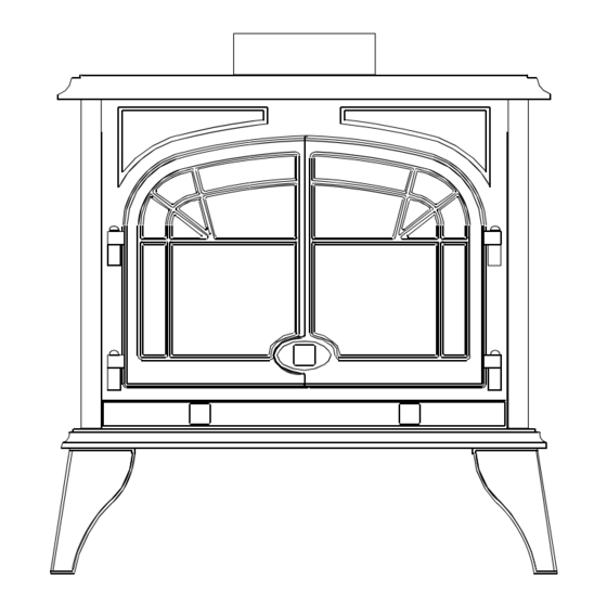
SPECIFICATIONS: HEIGHT: 24 3/8" WIDTH (EXCLUDING LEGS): 24" DEPTH : 16" WIDTH (INCLUDING LEGS): 24 1/2" FLUE SIZE: 4" exhaust, 6 5/8" intake Figure 1 CLEARANCES: Refer to Figures 2A & 2B The following clearances to combustibles must be maintained: Figure 2A Unit* to sidewall: 7"... -
Page 5: Venting Guidelines
NOTE: When the unit is installed directly on carpeting, tile, or other combustible materials other than wood flooring, it must be installed on a metal or wood panel extending the full width and depth of the unit. Figure 2B VENTING GUIDELINES THIS FIREPLACE IS APPROVED FOR USE WITH ONE OF THE FOLLOWING DIRECT VENT CHIMNEY SYSTEMS FOR HORIZONTAL &... -
Page 6: Termination Vent Cap Location
TERMINATION VENT CAP LOCATION: This gas appliance must not be connected to a chimney flue serving another type of appliance. GENERAL: Terminations against vinyl siding must use a vinyl siding protector. Follow instructions included. DO NOT RECESS TERMINATION KIT INTO OUTSIDE BUILDING MATERIALS - i.e.: brick, stone, siding, etc.. If necessary, extend framing so that termination kit will be exposed once building materials are installed. - Page 7 MINIMUM / MAXIMUM VENTING REQUIREMENTS: Minimum vertical vent run: 2 ft. Maximum vertical vent run: 32 ft. RESTRICTOR REQUIREMENTS: Optional, depending on venting configuration. Minimum horizontal vent run: 9 in. Maximum horizontal vent run: 12 ft.* *IMPORTANT: 1/4" incline per horizontal foot must be maintained.
- Page 8 HORIZONTAL TERMINATIONS EXAMPLE OF TYPICAL HORIZONTAL TERMINATION The minimum horizontal venting configuration is 2 ft. vertical from the top of the fireplace followed by a 90-degree elbow, then 9 in. min. horizontal thru exterior wall. See Figure 4. IMPORTANT: PASS-THRU WALL THICKNESS: The Dura-Vent DV-GS 4"...
- Page 9 RESTRICTOR USAGE / INSTALLATION The OPTIONAL restrictor plate included in the fireplace components packet can be installed as either a large or small restrictor, depending on your specific venting configuration. It is sized as the ‘large’ restrictor. To reduce the restrictor to a smaller size, remove one or both sections (without the tabs) at perforation and discard, Figure 6A.
-
Page 10: Fan Installation (Optional)
FAN INSTALLATION (OPTIONAL) AN OPTIONAL FAN KIT, PART #DUL-028, IS AVAILABLE FOR THIS FIREPLACE AND MAY BE PURCHASED FROM YOUR DEALER. INSTALLATION AND REPAIR OF THIS FAN SHOULD BE DONE ONLY BY A QUALIFIED INSTALLER. This optional fan kit includes: - Right &... - Page 11 Figure 7D Figure 7E 7. Mount the speed control box onto the left side of 8. Place the temperature control switch (magnet the gas valve control dashboard by aligning the attached) onto the bottom of the firebox as close holes in the box to the holes in the dashboard and to the center as possible.
-
Page 12: Position The Unit
POSITION THE FIREPLACE 1. Determine the exact position of your fireplace and location where the chimney will exit to the outside. If possible place the fireplace in such a manner that the piping will be placed between two studs so additional framing is not necessary. -
Page 13: Chimney Framing Dimensions
VERTICAL TERMINATIONS IMPORTANT: THIS FIREPLACE IS APPROVED FOR USE WITH THE FOLLOWING DIRECT VENT CHIMNEY SYSTEMS: Simpson Dura-Vent DV-GS 4" x 6 5/8" & Ameri-Vent Direct Vent 4" x 6 5/8" IMPORTANT: Restrictor usage is optional, depending on your specific venting configuration. Refer to page #7 for complete information. -
Page 14: Gas Line Installation Requirements - Minimum/Maximum Pressures
RUN THE GAS LINE. CAUTION: Installation of the gas line must only be done by a qualified person in accordance with local building codes. NATURAL GAS: The minimum inlet gas supply pressure: 5.0 inches W.C. The maximum inlet gas supply pressure: 10.5 inches W.C. Manifold Pressure: 3.5 inches W.C. -
Page 15: Millivolt Board Removal / Installation
MILLIVOLT BOARD REMOVAL / INSTALLATION. NOTE: This fireplace is equipped with the millivolt board system already installed. Follow these procedures should it need replacing or is removed for servicing. MILLIVOLT BOARD REMOVAL: CAUTION: If the burner and/or pilot has been burning, the logs will be warm and will continue to hold heat. Use the appropriate protection when handling the logs or any component on the millivolt board to avoid personal injury or burns. - Page 16 INSTALLING THE MILLIVOLT BOARD: NOTE: The millivolt board is fitted with a gasket to seal the board. Make certain this gasket is properly placed around the opening before installing the millivolt board. REFER TO FIGURES 11 & 12 ON PAGE #13 FOR STEPS #1 - #5. Place the board into the firebox, lining up the six 1/4"...
-
Page 17: Log Installation
LOG INSTALLATION. This 6 pc. log set includes: (1) ‘DU’ log (1) ‘OB2' log (1) ‘OB3' log (2) ‘OB5' log (1) ‘C’ log (1) Klinkers Packet (1) Embers Packet BASE LOGS & EMBERS INSTALLATION: Set the DU, OB2, and OB3 logs into position on the millivolt board as shown in Figures 13A &... -
Page 18: Thermostat - Remote Control - Wall Switch Installation
Follow instructions included with each assembly. Thermostat Wiring Diagram NOTE: Lift up the ‘Kozy Heat’ panel under the fireplace to access the gas valve & controls. Push the panel ‘in’ slightly and it will stay in position. Disconnect the on/off rocker switch wires from the top &... -
Page 19: Complete The Installation
COMPLETE THE INSTALLATION THIS STEP SHOULD ONLY BE DONE BY A QUALIFIED INSTALLER OR SERVICE TECHNICIAN Perform lighting and shutdown procedures as described on pages #18-#19. This should be done prior to replacing the glass so that any necessary adjustments can be made and proper operation verified. SEASONAL HEAT DUMP: This fireplace has been manufactured with an adjustable heat dump outlet inside the firebox (at the top). -
Page 20: Lighting & Shutdown Procedures
LIGHTING AND SHUTDOWN. NOTE: Prior to lighting, check all fittings for leakage. This is accomplished by applying soapy water on all connections made. If there is any leakage, bubbles will appear at the point of connection. If bubbles occur, tighten the fittings until the bubbles no longer appear. IMPORTANT: TEST ALL CONNECTIONS WHETHER FIELD OR FACTORY MADE. - Page 21 Push in the control knob all the way and hold in. Press the square piezo igniter button (B). The pilot will generally light with two or three pushes on the igniter. Hold the knob in for about one (1) minute after the pilot is lit. Release knob and it will pop back out.
-
Page 22: Manifold (Outgoing) & Inlet (Incoming) Pressure Check Procedures
PRESSURE TESTING MANIFOLD & INLET PRESSURE IMPORTANT NOTICE: A pressure check tap for both the manifold (outgoing) and inlet (incoming) pressure has been incorporated into the valve by Honeywell. The right pressure tap is the manifold pressure and the left pressure tap measures the incoming pressure. -
Page 23: Maintenance Requirements
MAINTENANCE REQUIREMENTS MILLIVOLT BOARD SYSTEM 1. The appliance should be inspected at least once a year by a professional service person. 1. Annual cleaning of the burner is required. The burner tube may be removed for easier access. Refer to NOTE: INSTALLATION AND REPAIR SHOULD BE pages #13 &... -
Page 24: Trouble Shooting Guide
TROUBLE SHOOTING GUIDE NOTE: The regulator board includes the following items: Regulator, generator, pilot, piezo, electrode, rocker switch, burner, orifice and orifice holder. If any of these items are defective, contact your dealer for the appropriate repair / replacement procedures to follow. WARNING: DO NOT ATTEMPT TO SERVICE THIS UNIT IF YOU ARE NOT A QUALIFIED INSTALLER OR REPAIRMAN. - Page 25 PROBLEM CAUSE SOLUTION 3. Pilot won't stay lit. Not holding black control Hold button in longer to heat knob in long enough. thermocouple. Thermocouple connection loose Check connection on valve & tighten if at valve connection. necessary. Pilot hood misdirecting pilot flame Check pilot flame location.
-
Page 26: Replacement Parts
REPLACEMENT PARTS Replacement parts are available through your local dealer. Contact them for availability and pricing. MILLIVOLT BOARD AND PARTS DUL-800 Millivolt Board - Natural Gas 700-203 Manual Shut off Valve DUL-801 Millivolt Board - LP Gas 700-213B 18" Flexible Gas Line - Black 700-023 On/Off Rocker Switch 700-224... - Page 27 Hussong Manufacturing Co., Inc. warranties to the requirements listed below, beginning with the first day original purchaser of this Kozy Heat Fireplace, that it is of the second year and continuing through the tenth free of defects in materials and workmanship at the year, Hussong Manufacturing Co., Inc., will at its...
-
Page 28: Warranty Policy
LIFETIME WARRANTY IS EXTENDED AS FOLLOWS: Hussong Manufacturing warranties to the original purchaser that the firebox, heat exchanger, fiber logs, burner tube and glass of this Kozy Heat fireplace will not be defective in material or workmanship under normal use and service for as long as you own this product.
Need help?
Do you have a question about the 55801 Duluth and is the answer not in the manual?
Questions and answers