Advertisement
Quick Links
Advertisement

Subscribe to Our Youtube Channel
Related Manuals for Insportline Profigym C50


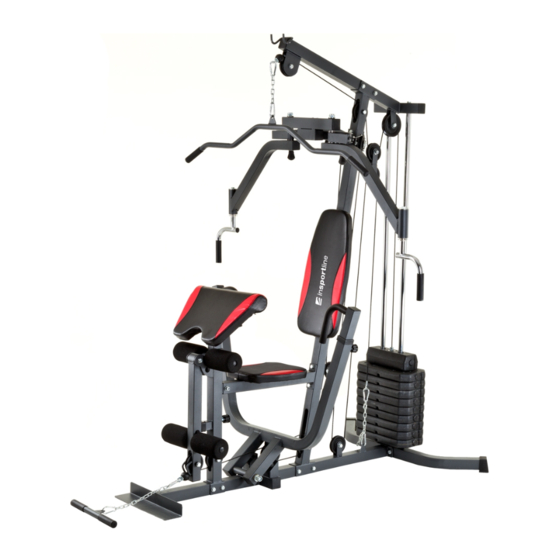
Summary of Contents for Insportline Profigym C50
- Page 1 USER MANUAL - EN IN 7186 Home gym inSPORTline Profigym C50...
- Page 2 PATRS LIST...
- Page 3 PATRS LIST...
-
Page 4: Assembly Instructions
ASSEMBLY INSTRUCTIONS STEP 1: : : : 1. Attach Main Base (1) to Rear Base (2), using two M10×70mm Hex Bolts (69), four M10 Washers (78) and two M10 Nylon Nuts (81). - Page 5 ASSEMBLY INSTRUCTIONS STEP2: : : : 1. Remove two M10×20mm Hex Bolts (72) and two M10 Washers (78) from two Weight Guide Tubes (3). 2. Insert the Weight Guide Tube (3) into the Rear Base (2), using two M10×20mm Hex Bolts (72) and two M10 Washers (78).
- Page 6 ASSEMBLY INSTRUCTIONS STEP3: : : : 1. Attach the Vertical Post (4) to the Main Base (1), using two M10×70mm Hex Bolts (69), four M10 Washers (78) and two M10 Nylon Nuts (81). 2. Remove two M10×20mm Hex Bolts (72) and two M10 Washers (78) from two Weight Guide Tubes (3).
- Page 7 ASSEMBLY INSTRUCTIONS STEP4: : : : 1. Attach Bench Press Arm (13)to Main Base (1), using Shaft (25),six Oil Bushing (Small) (43), two M16 Washers (77) and two M16 Nylon Nuts (80). 2. Insert the Left & Right Press Arms (17&18) into the Bench Press Arm (13), using two Quick Knobs (short) (45).
- Page 8 ASSEMBLY INSTRUCTIONS STEP5: : : : 1. Attach the Butterfly Extension (6) to Vertical Post (4), using two M10×70mm Hex Bolts (69), four M10 Washers (78) and two M10 Nylon Nuts (81). 2. Tap Oil Bushing (small) (43) to Right Adjustable Plate (16). 3.
- Page 9 ASSEMBLY INSTRUCTIONS STEP6: : : : 1. Attach Seat Cushion Support (9) to Vertical Post (4), using two M10×70mm Hex Bolts (69), four M10 Washers (78) and two M10 Nylon Nuts (81). 2. Attach Seat Support Post (10) to Seat Cushion Support (9),using one M10×65mm Hex Bolt (70), two M10 Washers (78) and one M10 Nylon Nut (81).
- Page 10 ASSEMBLY INSTRUCTIONS STEP7: : : : 1. Attach Backrest Cushion (30) onto Vertical Post (4), using two M8×65mm Hex Bolts (73) and two M8 Washers (79). 2. Attach Seat Cushion (29) onto Seat Cushion Support (9), using four M8×15mm Hex Bolts (74) and four M8 Washers (79).
- Page 11 ASSEMBLY INSTRUCTIONS...
- Page 12 ASSEMBLY INSTRUCTIONS STEP 8: 1. Start with the Upper Cable (53) a). With Upper Cable (53) in groove of Pulley (39), thread Upper Cable (53) through Top Beam (5). b). Install Pulley NO.1 (39) to Top Beam (5), using one M10x45mm Hex Bolt (71), two M10 Washers (78) and one M10 Nylon Nut (81).
- Page 13 ASSEMBLY INSTRUCTIONS...
-
Page 14: Exploded Drawing
EXPLODED DRAWING...
Need help?
Do you have a question about the Profigym C50 and is the answer not in the manual?
Questions and answers