Table of Contents
Advertisement
Quick Links
www.watchguardalarms.com.au
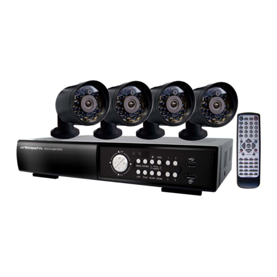
MODEL: DVR4ENTPACK4
Professional Surveillance Pack
Digital Video Recorder with 4 Security Cameras
'ADVANCED PRODUCT GUIDE'
N517
Please read instructions thoroughly before operation and retain it for future reference.
For the actual display & operation, please refer to your DVR in hand.
DVR4ENTPACK4_eng_manualV1.0.doc
1
Advertisement
Table of Contents

Related Manuals for Watchguard DVR4ENTPACK4


Summary of Contents for Watchguard DVR4ENTPACK4
- Page 1 MODEL: DVR4ENTPACK4 Professional Surveillance Pack Digital Video Recorder with 4 Security Cameras ‘ADVANCED PRODUCT GUIDE’ N517 Please read instructions thoroughly before operation and retain it for future reference. For the actual display & operation, please refer to your DVR in hand.
- Page 2 IMPORTANT SAFEGUARD CAUTION RISK OF ELECTRIC SHOCK CAUTION: To reduce the risk of electric shock, do not expose this apparatus to rain or moisture. Only operate this apparatus from the type of power source indicated on the label. The company shall not be liable for any damages arising out of any improper use, even if we have been advised of the possibility of such damages.
-
Page 3: Table Of Contents
TABLE OF CONTENTS 1. BEFORE USING THIS KIT .................5 1.1 Package Contents ....................... 5 1.2 Front Panel ........................5 1.3 Rear Panel ........................7 2. CONNECTION AND SETUP ................8 2.1 Camera Connection ..................... 8 2.2 DVR Power On ......................9 2.3 Date and Time Setting....................10 2.4 Clear Hard Disk...................... - Page 4 5.3.2 Detection Timer....................22 5.4 Detection Setting......................22 5.6 System Setting ......................24 5.6.1 Password Setting....................24 5.6.2 System Upgrade ....................24 5.6.3 Video Backup..................... 25 5.6.4 Clear All HDD Data .................... 26 5.7 Network ........................27 6. REMOTE OPERATION................28 6.1 Supplied Licensed Software…………………………………………………………………..28 6.1.1 Installation and Network Connection……………………………………………….
-
Page 5: Before Using This Kit
BEFORE USING THIS KIT 1. BEFORE USING THIS KIT 1.1 Package Contents … DVR … IR Remote Controller … User Manual, Quick Start Guide … CD w/Manuals and Software … DVR Power adaptor and cable … 4 x IR Cameras …... - Page 6 BEFORE USING THIS KIT ZOOM Press “ZOOM” button to enlarge the picture of selected channel (under the live mode) Press “SEQ” button to display each channel at full screen one by one. Press “SEQ” button again to escape the full screen cycle mode. Press to show the 4-channel display mode.
-
Page 7: Rear Panel
BEFORE USING THIS KIT 1.3 Rear Panel VIDEO IN (1 ~ 4) Connect to the video connector of a camera. Note: The DVR will automatically detect the video system of the camera, please make sure that the cameras are properly connected to the DVR and power is supplied before the DVR is turned on. AUDIO IN (1 ~ 4) Connect to the audio connector of a camera if the camera supports audio recording. -
Page 8: Connection And Setup
CONNECTION AND SETUP 2. CONNECTION AND SETUP Before the DVR is powered on, make sure you have installed a hard disk and connected at least one camera. For details, please refer to the following sections. Note: The DVR is designed to automatically detect the video system of the connected cameras (NTSC or ... -
Page 9: Dvr Power On
CONNECTION AND SETUP 2.2 DVR Power On This device should be operated only with the type of power source indicated on the manufacturer’s label. Connect the indicated DC power cord to the power adapter, and plug into an electrical outlet. The power LED on the front panel will be on. Note: Before the DVR is powered on, make sure the cameras are connected and power is supplied to ensure ... -
Page 10: Date And Time Setting
CONNECTION AND SETUP 2.3 Date and Time Setting Before operating your DVR, please set the date and time on your DVR FIRST. Note: Please DO NOT change the date or time of your DVR after the recording function is activated. Otherwise, the recorded data will be disordered and you ... -
Page 11: Clear Hard Disk
CONNECTION AND SETUP 2.4 Clear Hard Disk Each DVR4ENTPACK4 DVR includes a new HDD, but it is still recommended to clear all data in the hard disk for the first time when using the DVR to ensure the recorded data is stored properly. -
Page 12: Gui Display With Usb Mouse Control
GUI DISPLAY WITH USB MOUSE CONTROL 3. GUI DISPLAY WITH USB MOUSE CONTROL 3.1 Connect USB Mouse Connect your USB mouse to one of the USB ports on the DVR front panel, and check if there’s a mouse icon ( ) on the screen, indicating the USB mouse is detected properly. -
Page 13: Channel Switch
GUI DISPLAY WITH USB MOUSE CONTROL Click to select the audio channel you want: In the live mode, only the live audio channels can be selected. In the playback mode, live and playback audio channels can be selected. Click to enter the PTZ mode and show the PTZ control panel. -
Page 14: Main Menu
GUI DISPLAY WITH USB MOUSE CONTROL 3.3 Main Menu Right-click anywhere on the screen to show the main menu as follows, and right-click again to exit. For details about the menu structure, please refer to “APPENDIX 4 MAIN MENU STRUCTURE” on page 50. Main Menu Click to set the status display, image QUICK START... -
Page 15: Basic Operation
BASIC OPERATION 4. BASIC OPERATION 4.1 Live Page Icon Function Icon Function Icon Function Playback audio channel Live audio channel (1~4) Audio channel off (1~4) Digital zoom on Digital zoom off LAN connected Network disconnected Internet connected No USB device connected USB flash drive I device HDD overwrite USB mouse connected... -
Page 16: Playback
BASIC OPERATION 4.3 Playback Click “ ” on the quick menu bar to display the playback control panel, and click to play the latest recorded video clip, or click to enter the search list. Note: There must be at least 8192 images of recorded data for playback to work properly. If not, the device will stop playback. For example, if the IPS is set to 25, the recording time should be at least 327 seconds (8192 images/25 IPS) Note: During playback, the image size of the recording (FRAME, FIELD or CIF) will ... -
Page 17: Event Search
BASIC OPERATION 4.3.2 Event Search Click to quickly search the recorded files by four event lists: RECORD LIST/MOTION LIST/ALARM LIST/TIME LIST, or select FULL LIST to show all event logs. To quickly search the time you want, select “QUICK SEARCH”. Set the time range you want, and select “Start”... -
Page 18: Video Output Switch
BASIC OPERATION 4.5 Video Output Switch The DVR does not support simultaneous video output on a CRT monitor (connected to “MONITOR”) and an LCD monitor (connected to “VGA”). The default video output setting is “AUTO“, meaning the DVR will automatically detect the video output source. When “VGA” and “MONITOR” are both connected, the default monitor output is VGA. -
Page 19: Frequently-Used Functions
FREQUENTLY-USED FUNCTIONS 5. FREQUENTLY-USED FUNCTIONS 5.1 Quick Search Press “LIST” on the DVR front panel or select “EVENT INFORMATION” from the quick start menu to access the time search menu as follows: QUICK SEARCH DATE 2009/NOV/20 TIME 15:17:57 HARD DISK ALL HDD SEARCH START... -
Page 20: Detailed Record Setting
FREQUENTLY-USED FUNCTIONS IMAGE PER SECOND Select the images per second for MANUAL RECORD. 5.2.2 Detailed record setting Right-click to display the main menu, and select “ADVANCE CONFIG” “RECORD” Note: Please DO NOT change the date or time of your DVR after the recording function is activated. Otherwise, the recorded data will be disordered and you ... -
Page 21: Schedule Setting
FREQUENTLY-USED FUNCTIONS OVERWRITE Select “ON” to overwrite previously recorded data in your HDD when the HDD is full. When this function is on and the HDD is full, the DVR will clear 8GB data from the oldest date, providing continuous recording. EVENT RECORD ALL CHANNEL Select to record all channels (ON) or record the channel with an event only (OFF) for any event (motion/alarm/timer etc). -
Page 22: Detection Timer
FREQUENTLY-USED FUNCTIONS 5.3.2 Detection Timer Click “DETECTION” In “DETECTION TIMER”, select “ON” to enable record timer, and select the day and time for this function. SCHEDULE SETTING RECORD DETECTION TIMER DETECTION EXIT X axis 0 ~ 24 hours. Each time bar is 20 minutes. Y axis Sunday ~ Saturday 5.4 Detection Setting... - Page 23 FREQUENTLY-USED FUNCTIONS Note: The default setting of SS is 03, which means once an object is detected in more than 3 grids, the system will get triggered. So the value of SS must be less than the number of grids that you set up for the motion detection area TS (Time of Sensitivity) The “TS” function sets the sensitivity regarding how long one object can stay in the detection area before triggering the recording. The smaller the value, the higher the sensitivity for motion detection.
-
Page 24: System Setting
FREQUENTLY-USED FUNCTIONS 5.6 System Setting 5.6.1 Password Setting Right-click to display the main menu, and select “SYSTEM” “TOOLS” SYSTEM TOOLS LANGUAGE ENGLISH SYSTEM INFO ADMIN PASSWORD SETUP OPERATOR PASSWORD SETUP USB BACKUP UPGRADE SUBMIT EXIT ADMIN PASSWORD Click “SETUP” to change the administrator password. The default administrator password is 0000. -
Page 25: Video Backup
FREQUENTLY-USED FUNCTIONS 5.6.3 Video Backup Right-click to display the main menu, and select “SYSTEM” “USB BACKUP” Insert a compatible USB flash drive into the USB port at the front panel of the DVR. Note: Before using the USB flash drive, please use your PC to format the USB flash drive to FAT32 format first. For the list of compatible USB flash drives, please refer to “APPENDIX 2 COMPATIBLE USB FLASH ... -
Page 26: Clear All Hdd Data
FREQUENTLY-USED FUNCTIONS 5.6.4 Clear All HDD Data Right-click to show the main menu, and select “SYSTEM” “SYSTEM INFO” “CLEAR HDD” SYSTEM TOOLS BAUD RATE 2400 SYSTEM INFO HOST ID USB BACKUP AUTO KEY LOCK NEVER CLEAR HDD HDD-0 DVD BACKUP RESET DEFAULT SUBMIT... -
Page 27: Network
FREQUENTLY-USED FUNCTIONS 5.7 Network The description below is only for STATIC network type. PPPOE and DHCP settings need to be set from “Video Viewer”. For details, please see section 6. “Remote Operation” on page 30. STATIC ADVANCE CONFIG CAMERA NETWORK TYPE STATIC DETECTION 192.168.001.010... -
Page 28: Remote Operation
REMOTE OPERATION 6. REMOTE OPERATION You can also control the DVR remotely via the supplied licensed software “Video Viewer“, Internet Explorer web browser, and Apple’s QuickTime player. 6.1 Supplied Licensed Software The sections below describe frequently-used functions of the Video Viewer. 6.1.1 Installation &... - Page 29 REMOTE OPERATION Click “ “ “ “ to key in the default IP address, user name, password, and port number of the DVR you intend to connect. Click “ ” “ ” to search the available IP address(es) of other DVR(s) under the same domain as your PC IP address.
-
Page 30: Control Panel Overview
REMOTE OPERATION 6.1.2 Control Panel Overview Two control panels are available and can be switched depending on your use habit. Simplified Version (Default) ... - Page 31 REMOTE OPERATION Full Function Version Main Button Overview Button Simplified Full Function Description Click to show the predefined IP address(es). You Address Book can add, remove or search the IP address to log into the DVR remotely. Remote Click to go into the detailed Config DVR setting.
-
Page 32: General Operation
REMOTE OPERATION Button Function Description Simplified Full Record I Click to start I stop the manual recording. Record Stop Click to take a snapshot of the current view. The Snapshot snapshot will be saved in the path you specified in “Record Setting“. - Page 33 REMOTE OPERATION If “Manual” is checked, click “ “ or “ “ on the main control panel to start the manual recording immediately, and the recordings will be saved in the specified location. If “Motion“ and I or “Alarm“ are checked, the recording function will also be enabled at the remote side when any event is triggered at the DVR side, and the recordings will be saved in the specified location.
- Page 34 REMOTE OPERATION Function Description HDD Number/Channel Specify the hard disk (HDD Number) and channel number (Channel) within which have the video data you need. Download by Time Specify the time range which has the video data you want in the “Start Time” and “End Time” columns. Download by Event Select an event log from the event list.
-
Page 35: E-Map
REMOTE OPERATION 6.1.4. E-Map Video Viewer is also a Central Management System (CMS) software, which allows network device control & management for up to 16 devices simultaneously. Note: Before using this function, make sure Video Viewer is connected to all the devices you want to monitor. E-Map is ONLY available when the control panel is switch to the full function version. How to Add an E-Map Group STEP 1: In the simplified version, click “... - Page 36 REMOTE OPERATION ...
- Page 37 STEP 3: When the E-Map group is created, you will see the tree on the top-left panel, showing all the devices you’ve added to this group. Icon Description The connected device is a camera. When it’s selected, the icon will become red. The connected device is a DVR.
- Page 38 REMOTE OPERATION How to Edit I Remove an Existing E-Map Group For Google E-Map Group Right-click on the group name to show the shortcut menu list, and select “Edit E-MAP” or “Remove E-MAP“ as needed. You can also add a single E-Map group (Add Single E-MAP) or Building E-Map group (Add Building E-MAP) into the existing Google E-Map group.
- Page 39 For Single E-Map Group Right-click on the group name to show the shortcut menu list, and select “Edit E-MAP” or “Remove E-MAP” as needed. ...
- Page 40 For Building E-Map Group Right-click on the group name to show the shortcut menu list, and select “Edit E-MAP” or “Remove E-MAP” as needed. To edit or remove a certain level of the building E-Map group, right click on the level name, and select “Edit E-MAP“...
-
Page 41: Ie Web Browser
REMOTE OPERATION 6.2 Web Browser You can view the images or operate your DVR via a supported web browser. The DVR supports Microsoft Internet Explorer, Mozilla Firefox and Google Chrome web browsers. Note: The supported PC operating systems are Windows 7, Vista, XP and 2000. Step 1: Key in the IP address used by your DVR in the URL address box, such as 60.121.46.236, and press Enter. - Page 42 Click one of the numbers to switch to the channel you want to see Channel Selection in fullscreen Click to show 4-cut display. Display Mode Click to display each channel one by one, starting from CH1. When the last channel is displayed, the cycle repeats from CH1. To exit from this display mode, press any other channel display button Selection...
-
Page 43: Event Playback & Download
REMOTE OPERATION 6.2.1 Event Playback & Download Click to jump to the next/previous time interval in an hour, for example, Previous/ 11:00~12:00 or 14:00~15:00, and start playing the earliest event video Next Hour clip recorded during this whole hour. Increase the speed for fast forward. -
Page 44: Remotely Accessing Your Dvr
“PORT” from Port 80 to Port 82. You can then install the EagleEyes application on your mobile phone by downloading it from your mobile phone App Store. Use your External Static IP address and port 82 to connect to your DVR. Please Note: The Eagle Eyes application is not developed nor distributed by Watchguard Alarms™, therefore we are unable to provide service or troubleshooting for issues arising from the use of the app. ... -
Page 45: Appendix 1 Specifications
APPENDIX 1 SPECIFICATIONS DVR4CHSOV6H264 Video System PAL (auto detection) Video Compression Format H.264 Video Input 4 channels (composite video signal 1 Vp-p 75Ω BNC) Video Output (BNC) Main Monitor: For stable display Audio Input 4 audio inputs (Mono) Output 1 audio output Maximum Recording Rate Frame 704×576 with 25 IPS <PAL>... - Page 46 Camera Title Supports up to 6 letters Video Adjustable Hue I Saturation I Contrast I Brightness Date Display Format YYIMMIDD, DDIMMIYY & MMIDDIYY Daylight Saving Power Source (±10%) 19VDC Power Consumption (±10%) < 42 W Operating Temperature ( °C) 10° ~ 40°C Dimensions (mm)** 343(W) ×...
-
Page 47: Appendix 2 Compatible Usb Flash Drive List
APPENDIX 2 COMPATIBLE USB FLASH DRIVE LIST APPENDIX 2 COMPATIBLE USB FLASH DRIVE LIST Please upgrade the firmware of the DVR to the latest version to ensure the accuracy of the following table. If the USB flash drive is not supported by the DVR, the “USB ERROR“ message will be shown on the screen. -
Page 48: Appendix 3 Main Menu Structure
APPENDIX 3 MAIN MENU STRUCTURE APPENDIX 3 MAIN MENU STRUCTURE QUICK START GENERAL CHANNEL TITLE EVENT STATUS DATE DISPLAY IMAGE SIZE QUALITY IMAGE PER SECOND TIME SETUP DATE TIME DATE SETUP DATE INFO DISPLAY DATE OF MODE FORMAT DAYLIGHT DAYLIGHT SAVING SYSTEM TOOLS LANGUAGE... - Page 49 SAVE NETWORK SETTING SNTP NTP SERVER SYNC PERIOD DISPLAY FULL SCREEN DURATION DISPLAY COVERT HDD DISPLAY MODE DISPLAY OUTPUT PATH ALPHA BLENDING MANUAL RECORD ENABLE RECORD EVENT RECORD ENABLE TIMER RECORD ENABLE EVENT RECORD IPS TIMER RECORD IPS PRE-ALARM RECORD OVERWRITE EVENT RECORD ALL CHANNEL KEEP DATA LIMIT (DAYS)
-
Page 50: Appendix 4 Dvr Battery Replacement
APPENDIX 4 DVR BATTERY REPLACEMENT APPENDIX 4 DVR BATTERY REPLACEMENT DVR time reset after power failure, for example, caused by a power outage, will cause the disorder of the recorded data, and users may have problems in searching the event clip they want. To keep the DVR time from resetting, a non-chargeable lithium battery, CR2032, is installed in the DVR. -
Page 51: Appendix 5 Pin Configuration
APPENDIX 5 PIN CONFIGURATION APPENDIX 5 PIN CONFIGURATION Siren: When the DVR is triggered by alarm or motion, the COM connects with NO and the siren strobe will start wailing and flashing Magnetic Contact: When the magnetic contact is opened, the alarm will be triggered and recording will begin. ...
Need help?
Do you have a question about the DVR4ENTPACK4 and is the answer not in the manual?
Questions and answers