Sign In
Upload
Manuals
Brands
Omron Manuals
I/O Systems
DST1-ID12SL-1
Omron DST1-ID12SL-1 Manuals
Manuals and User Guides for Omron DST1-ID12SL-1. We have
3
Omron DST1-ID12SL-1 manuals available for free PDF download: Operation Manual
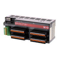
Omron DST1-ID12SL-1 Operation Manual (182 pages)
DST1 Series Safety I/O Terminals
Brand:
Omron
| Category:
I/O Systems
| Size: 2.71 MB
Table of Contents
Table of Contents
8
Precautions
15
General Precautions
16
Intended Audience
16
Safety Precautions
19
Operating Environment Precautions
21
Additional Precautions According to UL 1604
23
Glossary
24
Section 1 Overview
25
Overview
25
Overview
26
About the DST1-Series Safety I/O Terminals
26
DST1-Series Safety I/O Terminals Features
27
Standard Models
29
Input Terminals and I/O Terminals
29
Logic Terminals
29
Functions
30
Functions Supported by All DST1-Series Terminals
30
Input Terminals and I/O Terminals
31
Logic Terminals
32
Description of Safety Functions
33
DST1-Series Safety I/O Terminals
33
Safety Inputs
34
Safety Outputs
39
I/O Status Data
40
Logic Functions
41
Overview
41
Restrictions on the DST1-XD0808SL-1
41
Parameters that Can be Set
42
Monitoring Functions
45
Monitoring Status
45
Monitoring Parameters
47
Monitoring the Error History
49
Maintenance Functions of DST1-Series Safety I/O Terminals
51
Network Power Supply Voltage Monitor
51
Monitoring the Run Hours
53
Last Maintenance Date
56
Monitoring the Contact Operation Counters
58
Monitoring the Total on Times
61
Monitoring the Operation Time
65
Section 2 General Procedure
69
General Procedure
69
General Procedure
70
Installation
71
Connecting I/O Power and I/O Cable
72
Connecting the Communications Connector
75
Configuration
76
Node Address
76
Section 3 Configuration
77
Editing Parameters
78
Setting Parameters Using the Wizard
78
Parameter Groups
83
General Parameter Group
84
Safety Input Parameter Groups
86
Test Output Parameter Groups
88
Safety Output Parameter Groups
89
Operation Time Parameter Groups
90
Safety Input Logic Parameter Groups (Safety Input Logic)
91
Safety Output Logic Parameter Groups (Safety Output Logic)
92
3-1-10 Editing I/O Comments
93
Remote I/O Allocations
94
I/O Allocations
94
I/O Data
94
I/O Data Supported by each Model
96
I/O Assembly Data
101
Changing Default Standard I/O Assembly Data (DST1-XD0808SL-1 Only)
108
Section 4 Specifications
111
Specifications
111
Specifications
112
Common Specifications
112
Current Consumption and Weights
112
Devicenet Communications Specifications
113
Indicators
114
MS/NS Indicators
114
Configuration Lock Indicator
114
IN PWR/OUT PWR Indicators
115
I/O Indicators
115
Section 5 Dst1 Series Specifications
117
DST1 Series Specifications
117
Dst1-Id12Sl-1
118
Safety Input Specifications
118
Test Output Specifications
118
Nomenclature
118
Internal Circuits and Terminal Arrangement
119
Dimensions
120
Dst1-Md16Sl-1
121
Safety Input Specifications
121
Test Output Specifications
121
Safety Output Specifications for Semiconductor Outputs
121
Nomenclature
122
Internal Circuits and Terminal Arrangement
122
Dimensions
124
Dst1-Mrd08Sl-1
125
Safety Input Specifications
125
Safety Output Specifications for Relay Outputs
125
Nomenclature
126
Internal Circuits and Terminal Arrangement
126
Dimensions
129
Dst1-Xd0808Sl-1
130
Test Output Specifications
130
Safety Input Specifications
130
Safety Output Specifications for Semiconductor Outputs
130
Nomenclature
130
Internal Circuits and Terminal Arrangement
131
Dimensions
133
Response Performance
135
Reaction Time
136
Section 7 Troubleshooting and Maintenance
137
Troubleshooting and Maintenance
137
Indicators and Error Processing
138
Troubleshooting
139
Safety Input Errors
139
Test Output Errors
140
Safety Output Errors
141
Error History
142
Maintenance
144
Cleaning
144
Inspection
144
Replacing the DST1
145
Wiring Examples
147
Wiring and Configuration
148
Examples of Wiring for each Application
149
Logic Terminal Wiring Examples
157
Appendices
161
Index
175
Revision History
179
Advertisement
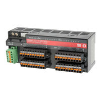
OMRON DST1-ID12SL-1 Operation Manual (105 pages)
Safety I/O Terminals
Brand:
OMRON
| Category:
Network Hardware
| Size: 1.69 MB
Table of Contents
Notice
5
OMRON Product References
5
Visual Aids
5
About this Manual
7
Precautions
9
Intended Audience
9
General Precautions
9
Safety Precautions
11
Precautions for Safe Use
12
Additional Precautions According to UL 1604
13
Regulations and Standards
13
Table of Contents
15
Section 1: Overview
19
1-1 Overview . . . . . . . . . . . . . . . . . . . . . . . . . . . . . . . . . . . . . . . . . . . .
20
Overview
20
About the DST1-Series Safety I/O Terminals
20
DST1-Series Safety I/O Terminals Features
20
Standard Models
22
1-3 Functions . . . . . . . . . . . . . . . . . . . . . . . . . . . . . . . . . . . . . . . . . . . .
23
1-2 Standard Models . . . . . . . . . . . . . . . . . . . . . . . . . . . . . . . . . . . . . . . . 22
23
Functions
23
DST1-Series Safety I/O Terminals
23
Safety Inputs
25
Test Outputs
26
Safety Outputs
26
1-4 Description of Safety Functions . . . . . . . . . . . . . . . . . . . . . . . . . . . . . . .
27
Description of Safety Functions
27
DST1-Series Safety I/O Terminals
27
Safety Inputs
28
Safety Outputs
32
Input Reaction Time
33
Output Reaction Time
33
I/O Status Data
34
Section 2: General Procedure
35
General Procedure
36
Installation
37
Connecting I/O Power and I/O Cable
38
Connecting the Communications Connector
39
Node Address
39
Configuration
39
Section 3: Configuration
41
3-1 Set I/O Parameters . . . . . . . . . . . . . . . . . . . . . . . . . . . . . . . . . . . . . . .
42
Set I/O Parameters
42
General Parameters
42
Safety Input Parameters
43
Test Output Parameters
44
Safety Output Parameters
44
Operation Time Parameters
45
3-2 Remote I/O Allocations . . . . . . . . . . . . . . . . . . . . . . . . . . . . . . . . . . . .
46
Remote I/O Allocations
46
I/O Allocations
46
I/O Data
46
I/O Data Supported by each Model
47
I/O Assembly Data
49
Section 4: Specifications
55
4-1 Specifications . . . . . . . . . . . . . . . . . . . . . . . . . . . . . . . . . . . . . . . . .
56
Specifications
56
Common Specifications
56
Current Consumption and Weights
56
Devicenet Communications Specifications
56
4-2 Indicators . . . . . . . . . . . . . . . . . . . . . . . . . . . . . . . . . . . . . . . . . . . .
57
Indicators
57
MS/NS Indicators
57
Configuration Lock Indicator
57
IN PWR/OUT PWR Indicators
57
I/O Indicators
58
5-1 Safety Input Terminal . . . . . . . . . . . . . . . . . . . . . . . . . . . . . . . . . . . . .
60
Section 5: DST1-Series
60
Safety Input Terminal
60
Safety Input Specifications
60
Test Output Specifications
60
Nomenclature
60
Internal Circuits and Terminal Arrangement
61
Dimensions
62
5-2 Safety I/O Terminal with Semiconductor Outputs . . . . . . . . . . . . . . . . . . . . . .
63
Safety I/O Terminal with Semiconductor Outputs
63
Safety Input Specifications
63
Test Output Specifications
63
Safety Output Specifications for Semiconductor Outputs
63
Nomenclature
63
Internal Circuits and Terminal Arrangement
64
Dimensions
65
5-3 Safety I/O Terminal with Relay Outputs . . . . . . . . . . . . . . . . . . . . . . . . . . .
66
Safety I/O Terminal with Relay Outputs
66
Safety Input Specifications
66
Test Output Specifications
66
Safety Output Specifications for Relay Outputs
66
Nomenclature
66
Internal Circuits and Terminal Arrangement
67
Dimensions
69
Section 6: Troubleshooting and Maintenance
71
Indicators and Error Processing
72
6-2 Troubleshooting . . . . . . . . . . . . . . . . . . . . . . . . . . . . . . . . . . . . . . . .
73
6-1 Indicators and Error Processing . . . . . . . . . . . . . . . . . . . . . . . . . . . . . . . 72
73
Troubleshooting
73
Safety Input Errors
73
Test Output Errors
74
Safety Output Errors
75
Error History
76
6-4 Maintenance . . . . . . . . . . . . . . . . . . . . . . . . . . . . . . . . . . . . . . . . . .
77
6-3 Error History . . . . . . . . . . . . . . . . . . . . . . . . . . . . . . . . . . . . . . . . . . 76
77
Maintenance
77
Cleaning
77
Inspection
77
Replacing the DST1
78
Section 7: Wiring Examples
79
Wiring and Configuration
80
7-2 Examples of Wiring for each Application . . . . . . . . . . . . . . . . . . . . . . . . . .
81
7-1 Wiring and Configuration . . . . . . . . . . . . . . . . . . . . . . . . . . . . . . . . . . . 80
81
Examples of Wiring for each Application
81
Emergency Stop Switch Dual Channel Inputs with Manual Reset
81
Two-Hand Input
81
User Mode Switch Input
82
Muting Lamp Output
83
Limit Switch Dual Channel Inputs and a Manual Reset
83
Safety Light Curtain Input
84
Semiconductor Outputs for Dual Channel Mode
85
Relay Outputs with Dual Channel Mode and EDM Input
86
Appendices
89
Devicenet Explicit Messages
89
Basic Format of Explicit Messages
89
Explicit Messages
90
Using Explicit Messages
97
Calculated Values of PFD and PFH
99
Calculated PFD Values
99
Calculated PFH Values
99
Index
105
Revision History
105
Omron DST1-ID12SL-1 Operation Manual (114 pages)
Safety I/O Terminals
Brand:
Omron
| Category:
I/O Systems
| Size: 7.02 MB
Table of Contents
OMRON Product References
7
Visual Aids
7
Trademarks and Copyrights
8
About this Manual
9
Read and Understand this Manual
10
Warranty and Limitations of Liability
10
Application Considerations
11
Disclaimers
12
Precautions
13
Glossary
19
Revision History
20
Table of Contents
21
Table of Contents
22
Section 1 Overview
24
Overview
25
About the DST1-Series Safety I/O Terminals
25
DST1-Series Safety I/O Terminals Features
26
Standard Models
28
Functions
29
DST1-Series Safety I/O Terminals
29
Safety Inputs
31
Test Outputs
32
Safety Outputs
33
Description of Safety Functions
34
DST1-Series Safety I/O Terminals
34
Safety Inputs
35
Safety Outputs
41
Input Reaction Time
42
Output Reaction Time
42
I/O Status Data
43
Section 2 General Procedure
44
General Procedure
45
Installation
46
Connecting I/O Power and I/O Cable
47
Connecting the Communications Connector
48
Node Address
49
Configuration
49
Section 3 Configuration
49
3-1 Set I/O Parameters
51
3-1-1 General Parameters
51
3-1-2 Safety Input Parameters
52
3-1-3 Test Output Parameters
53
3-1-4 Safety Output Parameters
54
3-1-5 Operation Time Parameters
54
Remote I/O Allocations
55
I/O Allocations
55
I/O Data
55
I/O Data Supported by each Model
56
I/O Assembly Data
58
Section 4 Specifications
63
Specifications
64
Common Specifications
64
Current Consumption and Weights
64
Devicenet Communications Specifications
64
Indicators
65
MS/NS Indicators
65
Configuration Lock Indicator
65
IN PWR/OUT PWR Indicators
66
I/O Indicators
66
Section 5 DST1-Series
67
Safety Input Terminal
68
Safety Input Specifications
68
Test Output Specifications
68
Nomenclature
68
Internal Circuits and Terminal Arrangement
69
Dimensions
70
5-2 Safety I/O Terminal with Semiconductor Outputs
71
Safety Input Specifications
71
Test Output Specifications
71
Safety Output Specifications for Semiconductor Outputs
71
Nomenclature
72
Internal Circuits and Terminal Arrangement
72
Dimensions
74
Safety I/O Terminal with Relay Outputs
75
Safety Input Specifications
75
Test Output Specifications
75
Safety Output Specifications for Relay Outputs
75
Nomenclature
76
Internal Circuits and Terminal Arrangement
76
Dimensions
78
Section 6 Troubleshooting and Maintenance
79
Indicators and Error Processing
80
Troubleshooting
81
Safety Input Errors
81
Test Output Errors
82
Safety Output Errors
83
Error History
84
Maintenance
85
Cleaning
85
Inspection
85
Replacing the DST1
86
Section 7 Wiring Examples
87
Wiring and Configuration
88
Examples of Wiring for each Application
89
Emergency Stop Switch Dual Channel Inputs with Manual Reset
89
Two-Hand Input
90
User Mode Switch Input
91
Muting Lamp Output
92
Limit Switch Dual Channel Inputs and a Manual Reset
93
Safety Light Curtain Input
94
Semiconductor Outputs for Dual Channel Mode
95
Relay Outputs with Dual Channel Mode and EDM Input
96
Appendices
97
Appendix 1: Devicenet Explicit Messages
98
A-1-1 Basic Format of Explicit Messages
98
A-1-2 Explicit Messages
100
A-1-3 Using Explicit Messages
107
Appendix 2: Calculated Values of PFD and PFH
109
A-2-1 Calculated PFD Values
109
A-2-2 Calculated PFH Values
109
Advertisement
Advertisement
Related Products
Omron DA002
Omron DST1-XD0808SL-1
Omron DST1-MD16SL-1
Omron DST1-MRD08SL-1
Omron DST1-ID
OMRON DST1 Series
Omron DST1-MD
Omron DST1-MR
Omron D4N-2D2GR
Omron D4N-8A2HR
Omron Categories
Blood Pressure Monitor
Controller
Accessories
Switch
Inverter
More Omron Manuals
Login
Sign In
OR
Sign in with Facebook
Sign in with Google
Upload manual
Upload from disk
Upload from URL