Sign In
Upload
Manuals
Brands
OMRON Manuals
Processor
CJ2*-CPU Series
OMRON CJ2*-CPU Series Manuals
Manuals and User Guides for OMRON CJ2*-CPU Series. We have
7
OMRON CJ2*-CPU Series manuals available for free PDF download: User Manual, Connection Manual, Manual, Datasheet
OMRON CJ2*-CPU Series User Manual (670 pages)
CJ2 CPU Unit Software
Brand:
OMRON
| Category:
Software
| Size: 21.02 MB
Table of Contents
Table of Contents
15
Introduction
7
Intended Audience
7
CJ2 CPU Unit Manuals
8
Manual Structure
11
Additional Information
11
Sections in this Manual
13
Table of Contents
15
Table of Contents
21
Safety Precautions
27
Application Precautions
31
Operating Environment Precautions
36
Regulations and Standards
37
Unit Versions of CJ2 CPU Units
39
Related Manuals
45
1 Overview
47
CJ2 CPU Unit Features
47
Overview of CJ2 CPU Units
47
Overview of CJ2 CPU Units
48
Overview
48
Overview
49
CJ2 CPU Unit Features
50
Basic Operating Procedure
58
2 Internal Memory in the CPU Unit
59
Memory Configuration
59
Overview
60
Memory Configuration
60
Built-In Flash Memory
60
Built-In Ram
60
Memory Areas and Stored Data
61
Transferring Data from a Programming Device to the CPU Unit
62
CPU Unit Operation
63
CPU Unit Operating Modes
63
CPU Unit Internal Operation
64
Overview
64
Startup Initialization
64
Cycle Time
66
Program Execution
66
I/O Refreshing
68
Processing at Power Interruptions
69
CPU Unit Operating Modes
70
Operating Modes
70
Checking the Operating Mode
71
Changing the Operating Mode
72
Operating Mode Details
76
CPU Unit Initialization
77
Overview of CPU Unit Initialization
78
CPU Unit Initial Settings
78
CPU Unit Initialization
78
Dip Switch
78
Plc Name
80
Routing Tables
81
PLC Setup
84
Creating I/O Tables
85
I/O Tables
85
Automatic Allocation
86
Manual Allocation
86
Setting Routing Tables
87
Routing Tables
87
Local Network Table
88
Relay Network Table
88
Cases in Which Routing Tables Are Required
89
Setting and Transferring Routing Tables
90
Setting Allocated DM Area Words for Special I/O Units and CPU Bus Units
91
Setting Procedure
91
CPU Bus Unit Setup Area
92
Setting Procedure
92
Understanding Programming
93
Programming
95
Programming Overview
95
Program Capacity
97
Basic Ladder Diagram Concepts
98
ST Language
100
SFC Overview
101
Tasks
103
Overview of Tasks
103
Cyclic Tasks
106
Cyclic Task Status
108
Task Control Instructions
109
Interrupt Tasks
112
External Interrupts
120
Designing Tasks
122
Flags Related to Tasks
125
Sections
132
Overview of Sections
132
Function Blocks
134
Features of Function Blocks
134
Function Block Specifications
136
Symbols
139
Overview
139
Types of Symbols
140
Variables in Function Blocks
141
Global Symbols
142
Local Symbols
142
Network Symbols
143
Network Symbols (CJ2H-CPU6@-EIP and CJ2M-CPU3@ Only)
143
Variables in Function Blocks
147
Symbol Data Types
148
Specifying Arrays
149
Automatic Address Allocation to Symbols
153
Instructions
154
Basic Understanding of Instructions
154
Instruction Conditions
155
Instruction Location and Execution Conditions
156
Instruction Variations
157
Execution Conditions
157
Specifying Operands
161
Specifying Operands
163
Data Formats
169
I/O Refresh Timing
173
Cyclic Refresh
173
Index Registers
178
What Are Index Registers
178
Using Index Registers
178
Processing Related to Index Registers
183
Monitoring Index Registers
184
Sharing Index and Data Registers between Tasks
185
Specifying Address Offsets
187
Overview
187
Examples of Address Offset Application
189
Checking Programs
190
Errors During CX-Programmer Input
190
Program Checks with the CX-Programmer
190
Debugging with the Simulator
191
Error Simulation Function
193
Program Execution Check
194
Other Errors
195
Precautions
197
Condition Flags
197
Special Program Sections
202
I\/O Memory Areas
207
I/O Memory Areas
207
I/O Memory Area Overview
208
I/O Memory Areas
208
I/O Memory Area Structure
210
Holding I/O Memory Values
212
I/O Area
214
Input Bits
214
Output Bits
216
Data Link Area
219
Synchronous Data Refresh Area
220
CPU Bus Unit Area
221
Special I/O Unit Area
222
Pulse I/O Area
223
Serial PLC Link Area
224
Devicenet Area
225
Work Area
226
Holding Area
227
Self-Maintaining Bits
227
Auxiliary Area
229
Temporary Relay Area
230
Data Memory Area
231
Extended Data Memory Area
234
Automatic Address Allocation
234
File Memory
235
Trace Memory
235
Timer Areas
238
Counter Areas
240
Task Flags
241
Index Registers
242
Data Registers
247
Condition Flags
249
Clock Pulses
251
File Operations
253
File Memory
254
File Operations
254
Types of File Memory
254
Initializing File Memory
255
Memory Card Precautions
257
Memory Card Recognition Time
257
Types of Files Stored in File Memory
259
File Types
259
Program/Network Symbol File
259
Parameter File
260
Data File
260
Comment File
261
Program Index File
261
Unit Backup File
261
Creating and Saving Files for File Memory
262
File Memory Operations
263
Types of File Memory Operations
263
Backup Restore Operation
264
File Memory Operating Procedures and File Memory Files
265
Files Automatically Transferred at Startup
265
General-Purpose Files
267
Restrictions on File Use
271
File Sizes
272
Relation between Support Software and File Memory Files
273
I\/O Allocations and Unit Settings
275
I/O Allocations
275
I/O Allocations
276
Automatic Allocation
279
Manual Allocation
283
Allocating First Words to Racks
288
I/O Table Errors and Precautions
291
Setting CPU Bus Units and Special I/O Units
294
Setting Parameters
294
Data Exchange
298
Special I/O Units
298
Fins Commands
299
Cpu Bus Units
300
Plc Setup
303
Overview of the PLC Setup
304
PLC Setup Settings
306
PLC Setup Settings
307
Startup Operation Settings
307
Iom Hold Bit Startup Hold Setting
308
Execution Setting
309
CPU Unit Settings
310
Execute Process
310
Background Execution Settings
314
Retry Counts
315
Timings/Synchronous Settings
316
Watch Cycle Time
316
Scheduled Interrupt Interval
318
Power off Detection Delay Time
319
Power off Interrupt Disabled
320
Special I/O Unit Cyclic Refreshing
321
Disable Siou Cyclic Refresh
321
Basic I/O Unit Rack Response Times
323
Serial Port Settings
325
Peripheral Service
332
Set Time to All Events
332
FINS Protection
333
Settings for Fins Write Protection Via Network
333
I/O Module
334
10 CPU Unit Functions
335
Clock Functions
337
Times Stored in Memory
338
Power on Clock Data
338
Power Interruption Time
339
Total Power on Time
339
Free-Running Timers
340
Cycle Time/High-Speed Processing
341
Minimum Cycle Time
341
Maximum Cycle Time
342
Monitoring the Cycle Time
343
High-Speed Inputs
343
Background Execution
344
Programming Example
350
High-Speed Interrupt Function
353
Startup Settings and Maintenance
356
Holding Settings for Operating Mode Changes and at Startup
356
Power off Detection Delay Setting
358
Disabling Power off Interrupts
359
RUN Output
360
Automatic Transfer at Startup
361
Unit Management Functions
369
Basic I/O Unit Management
369
CPU Bus Unit Flags/Bits
371
Special I/O Unit Flags/Bits
372
Memory Management Functions
373
Automatic Backup
373
EM File Memory Functions
375
Comment Memory
376
Replacing the Entire Program During Operation
377
Example Programs
380
Security Functions
384
Write-Protection Using the DIP Switch
384
Read Protection Using Passwords
384
Operating Procedure
385
Enabling/Disabling Saving to Memory Cards
387
Enabling and Disabling Program Overwriting
388
Program Operation Protection Using Production Lot Numbers
389
Write Protection from FINS Commands
390
PLC Names
394
Debugging
397
Forced Set/Reset
397
Test Input
398
Differential Monitoring
398
Online Editing
399
Turning off Outputs
401
Tracing Data
402
Storing the Stop Position at Errors
410
Failure Alarm Instructions
411
Simulating System Errors
412
Failure Point Detection
413
Synchronous Unit Operation
415
Overview
415
Application Example
417
Details on Synchronous Unit Operation
418
Synchronous Unit Operation Specifications
421
Synchronous Data Refresh
422
Restrictions in Using Synchronous Unit Operation
426
Application Procedure
428
PLC Setup
429
Writing the Synchronous Interrupt Task
431
Adjusting and Troubleshooting Synchronous Unit Operation
432
Programming Devices and Communications
437
Accessing a PLC from the CX-Programmer
438
Overview
438
System Configurations for Accessible Plcs
440
Accessing a PLC from the CX-Programmer
444
Automatic Online Connection
447
Serial Communications
451
Overview of Serial Communications
451
No-Protocol Communications System
453
Host Link Fins
455
Operating Specifications
457
System Configuration
457
Communications Networks
465
CPU Unit Cycle Time
469
Monitoring the Cycle Time
470
Computing the Cycle Time
472
CPU Unit Operation Flowchart
472
Cycle Time Overview
473
I/O Unit Refresh Times for Individual Units
475
Cycle Time Calculation Example
479
Online Editing Cycle Time Extension
481
I/O Response Time
481
Response Time for Input Interrupts
482
Response Performance of Serial PLC Links
483
Advertisement
OMRON CJ2*-CPU Series User Manual (425 pages)
CJ2 CPU Unit Hardware
Brand:
OMRON
| Category:
Processor
| Size: 9.04 MB
Table of Contents
Introduction
7
Applicable Products
7
Intended Audience
7
CJ2 CPU Unit Manuals
8
Manual Configuration
9
Hardware User’s Manual (Cat. No. W472)
9
Manual Structure
11
Page Structure
11
Special Information
11
Additional Information
11
Sections in this Manual
13
Table of Contents
15
Application Considerations
20
Suitability for Use
20
Safety Precautions
23
Definition of Precautionary Information
23
Symbols
24
Application Precautions
27
Power Supply
27
Installation
27
Wiring
28
Handling
28
External Circuits
31
Operating Environment Precautions
32
Regulations and Standards
33
Conformance to Shipbuilding Standards
34
Usage Conditions for NK and LR Shipbuilding Standards
34
Unit Versions of CJ2 CPU Units
35
Notation of Unit Versions on Products
35
Confirming Unit Versions with Support Software
35
PLC Information
35
Unit Manufacturing Information
36
Unit Versions and Programming Devices
39
Pull-Down List for PLC Models
39
Troubleshooting Problems with Unit Versions on the CX-Programmer
40
Related Manuals
41
Overview
43
Overview of CJ2 CPU Units
44
CJ2H CPU Units
45
CJ2M CPU Units
45
Overview
45
CJ2 CPU Unit Features
46
Fast, with Large Memory Capacity
46
High-Speed Processing
46
Built-In Ethernet/Ip Port
47
Built-In USB and Ethernet/Ip Ports
47
General-Purpose Networks for Support Software Interface
47
High-Speed, High-Capacity Data Links with User-Set Refresh Cycles
47
Access from Host Devices Is Enabled Using Tags
48
Network Symbols (Tags) for Flexible Support of Program Changes
48
Tag Access
48
Easier Programming
49
Synchronous Unit Operation
49
Create and Use Data Structures
50
Improved Debugging
51
Add a Serial Option Board (CJ2M-CPU3@ Only)
52
Use Pulse I/O and Interrupt Inputs (CJ2M CPU Units Only)
53
Basic Operating Procedure
54
Connecting Online to the PLC
54
I/O Allocations
54
Setting Devices and Hardware
54
General Specifications
55
Performance Specifications
56
Index
57
Function Specifications
63
Basic System Configuration and Devices
71
Expanded System Configuration
71
Basic System Configuration
72
CPU Rack
72
Expansion Racks
72
Pulse I/O Modules (CJ2M CPU Unit Only)
77
Serial Option Boards (CJ2M-CPU3@ Only)
77
CJ-Series Power Supply Units
77
Memory Cards
78
I/O Control Unit
78
End Cover
78
Maximum Number of Expansion Racks
81
Units
82
Configuration Units
84
Maximum Number of Units
84
Models of Configuration Units
84
CJ-Series Basic I/O Units
85
Input Units
85
Output Units
86
Mixed I/O Units
87
CJ-Series Special I/O Units
88
Calculating Unit Current Consumption
92
Maximum Current and Power Supplied by Power Supply Units
92
Example Calculations
93
Additional Information
94
Rack Current Consumption and Width Display
94
Calculating Power Consumption
95
Basic PLC Power Consumption (W_PLC)
95
Basic I/O Unit Power Consumption (W_IO_ONOFF)
95
Calculation Examples
96
Average Power Consumption (W)
96
Expanded System Configuration
97
Serial Communications
97
System Configuration Example
98
Communications Networks
99
Communications Network Systems
99
Communications Network Overview
100
Nomenclature and Functions
101
CPU Units
102
CPU Section
102
Nomenclature and Functions
102
CPU Unit Status Indicators
104
Memory Card Indicators
105
DIP Switch
106
Display and Indicators for Built-In Ethernet/Ip Port
108
Built-In Ethernet/Ip Section (CJ2H-CPU6@-EIP and CJ2M-CPU3@ Only)
108
Seven-Segment Display
109
Status Indicators: MS, NS, COMM, 100M, and 10M
109
Rotary Switches
111
Setting the Unit Number
111
Left/Right Dot Leds
111
Node Address Setting Switches
112
Relationship with IP Address
112
Memory Card
113
Models and Specifications
113
Operating Procedures
113
Before Using a Memory Card
114
Installing the Memory Card
114
Installing and Removing
114
Removing the Memory Card
115
Installing the Memory Card into a Personal Computer
116
Pulse I/O Modules (CJ2M CPU Unit Only)
117
Models and Specifications
117
Part Names and Functions
117
Connecting Pulse I/O Modules to the CPU Unit
118
Pulse I/O Module Detection
118
Pulse I/O Module Status Indicators
119
Mounting an Option Board
120
Serial Option Boards (CJ2M-CPU3@ Only)
120
Overview
120
Power Supply Units
121
Models and Specifications
121
Components
124
AC Input
125
DC Input
125
Lg
125
Gr
125
RUN Output (CJ1W-PA205R Only)
126
Alarm Output (CJ1W-PA205C Only)
126
Selecting a Power Supply Unit
127
Condition 1: Current Requirements
127
Current Consumption at 5 VDC
127
Current Consumption at 24 VDC
127
Basic I/O Units with Terminal Blocks
128
Interrupt Input Units
128
CJ-Series Basic I/O Units
128
Input Signal Width
129
Thirty-Two/Sixty-Four-Point Basic I/O Units with Connectors
130
Sixty-Four-Point Units
131
I/O Control Units and I/O Interface Units
132
System Configuration
132
Component Names
132
Support Software
133
4-1 Support Software
134
CX-One FA Integrated Tool Package
134
Support Software
134
CX-Programmer
135
CX-Integrator
136
Network Configurator
136
Connection Methods
137
Connecting by USB
137
Connecting Cable
137
Before Connecting
137
CX-Programmer Settings
138
Restrictions on Connecting by USB
138
Connecting by RS-232C
139
Setting the Communications Protocol
140
Connecting to Ethernet (CJ2H-CPU6@-EIP and CJ2M-CPU3@ Only)
141
Installation
145
Fail-Safe Circuits
146
Managing CPU Unit Errors
146
Managing Output Malfunctions
146
Order of Powering up the CPU Unit and Controlled System
146
Electrical Diagram
147
Emergency Stop Circuit
147
Interlock Circuits
147
Accessibility for Operation and Maintenance
148
Improving Noise Resistance
148
Installation and Wiring Precautions
148
Installation in Cabinets or Control Panels
148
PLC Orientation
149
Control Panel Installation Dimensions
150
Installation in a Control Panel
150
Routing Wiring Ducts
151
Wiring Ducts
151
Assembled Appearance and Dimensions
152
20-MM-Wide Units
153
Design Example for Width W
155
Installation Height
156
Connecting PLC Components
157
DIN Track Installation
159
DIN Track and Accessories
160
Connecting CJ-Series Expansion Racks
161
CS/CJ-Series I/O Connecting Cables
161
Cable Connections
162
Connecting the Simple Locking Connectors
162
AC Power Source
164
AC Power Supply Units
164
Isolation Transformer
164
Power Supply Wiring
164
Crimp Terminals
165
DC Power Supplies
166
Power Supply Capacity
166
Wiring in Which the 24-V Power Supply will Short
166
Grounding
167
Output Specifications
168
PLC Input Unit Wiring Example
169
External Display Device Connection Example
170
Electric Wires
171
Wiring CJ-Series Basic I/O Units with Terminal Blocks
171
Wiring Basic I/O Units with Connectors
173
Using User-Made Cables with Connector
174
Wire Size
175
Wiring Procedure
175
Connecting Pulse I/O Modules to External I/O Devices
177
Connecting Pulse I/O Modules to External I/O Devices (CJ2M CPU Unit Only)
177
Connecting to Connector-Terminal Block Conversion Units or I/O Relay Terminals
177
Connecting I/O Devices
179
DC Input Units
179
Input Devices
179
AC Input Units
180
Precautions When Connecting a Two-Wire DC Sensor
180
Output Short-Circuit Protection
182
Output Surge Current
182
Output Wiring Precautions
182
Transistor Output Residual Voltage
182
Connecting through an Ethernet Cable (CJ2H-CPU6@-EIP and CJ2M-CPU3@ Only)
183
Precautions on Laying Twisted-Pair Cable
183
Connecting the Cable
184
Ethernet Connectors
184
Control Panel Installation
186
Temperature
186
Natural Cooling
186
High Temperatures
186
Forced Air Circulation (by Fan in Closed Panel)
187
Room Cooling
187
Low Temperatures
187
Humidity
188
Vibration and Shock
188
Atmosphere
188
Electrical Environment
189
Arrangement of PLC and Units
189
PLC Installation Location
189
Input Signal Noise Countermeasures
190
Power Supply System Diagram
190
Wire Layout for the Power Supply System
190
Wiring External I/O Signal Lines
190
External Wiring
191
Wiring Routes
191
Parallel Wiring (Single Phase)
192
Partitioning Methods for Signal and Power Supply Cables
192
Wiring Methods
192
Example: Separating PLC from Power Lines
193
Other Precautions
193
Grounding Methods and Precautions
194
Principles of One-Point Grounding
194
Grounding for AC Power Supply Units
195
PLC Ground Terminals
195
Precautions When Grounding
195
Shielded Cable Ground
195
Troubleshooting
197
CPU Unit Errors
198
Errors and Remedies
198
Checking Errors
198
Checking the Indicators
198
Checking Error Status with the CX-Programmer
199
Checking Detailed Status
199
Reading Error Log Information
199
Error Log Information
200
Checking Error Log Information
200
CX-Programmer PLC Error Window
200
Directly Monitoring the Area Where Error Log Information Is Stored
200
I/O Table Verification
201
Types of Errors
202
Handling Errors
203
Power Supply Errors
203
CPU Standby Errors
204
Recovery Processing Flow
204
Error Causes and Remedies
204
CPU Reset
205
Cpu Errors
206
Communications Error (Peripheral (USB) Port)
207
Communications Error (Serial Port (RS-232C))
207
Cycle Time Exceeded Error (Fatal Error)
208
I/O Bus Error (Fatal Error)
209
I/O Setting Error (Fatal Error)
211
Memory Error (Fatal Error)
212
Basic I/O Error (Non-Fatal Error)
214
Option Board Errors
215
Battery Error (Non-Fatal Error)
216
CPU Bus Unit Error (Non-Fatal Error)
217
Special I/O Unit Error (Non-Fatal Error)
218
Special I/O Unit Setting Error (Non-Fatal Error)
219
Error Causes and Remedies for Synchronous Unit Operation Settings
220
Checking Built-In Ethernet/Ip Port Error Status
221
Troubleshooting Built-In Ethernet/Ip Port Errors (CJ2H-CPU6@-EIP and CJ2M-CPU3@ Only)
221
Checking Error Status at the Ethernet/Ip Port Seven-Segment Display
222
Errors Related to CPU Unit Data Exchange
222
Errors Related to the CPU Unit
222
Errors Related to the Control Bits
222
Errors Related to the Tag Data Links
223
Errors Related to Memory Access
223
Errors Related to the Network
223
Errors Related to Units
223
Non-CPU Unit Errors and Remedies
224
Error Causes and Remedies
224
Connecting Via the Peripheral (USB) Port
227
CX-Programmer Connections
227
Connecting Via the Serial Port
229
Inspection and Maintenance
231
Inspection Points
232
Periodic Inspection Points
232
Tools Required for Inspections
233
Unit Replacement Precautions
234
Replacing the Battery
235
Battery Replacement
235
Purpose of the Battery
235
Battery Service Life and Replacement Period
235
Low Battery Indicators
236
Replacement Battery
236
Replacement Procedure
236
Operation When Battery Is Exhausted or Not Installed
238
Continuing Operation
238
Saving Data
238
Setup Method
239
Power Supply Unit Replacement Time
240
Power Supply Unit Replacement Notification Module
240
Power Supply Unit with Replacement Notification
240
Principle of Replacement Notification
240
Alarm Output (Replacement Notification Output)
241
Function
241
Replacement Notification Function Displays
241
Display and Alarm Output Operation
242
Maintenance Function Using the TEST Switch
242
Normal Display: Replacement Notification Display
242
Operation at Power off
243
Operation When Turning on the Power
243
Operation When TEST Switch Is Pressed
244
Self-Diagnostic Function
244
Comparison between the CJ1W-PA205C and CJ1W-PA205R
245
Backup Operations
247
Backing up Data
248
Using a Computer to Back up Data to the Computer
248
Using a Computer to Back up Data
249
PLC Backup Tool
249
Applicable Units
249
Applicable Data
249
PLC Backup Tool Operations
250
Restrictions
250
Starting the PLC Backup Tool
250
Comparing Data
251
Restoring Data
252
Simple Backup
253
Overview
253
Backing up Data from the CPU Unit to the Memory Card
254
Restoring Data from the Memory Card to the CPU Unit
254
Operating Procedures
254
Comparing Data in the Memory Card and CPU Unit
255
Verifying Backup Operations with Indicators
256
Related Auxiliary Bits/Words
258
Time Required for Simple Backup
258
Data Backed up Using Simple Backup
258
Symbol Tables, Comments, and Program Index Files
259
Parameter Files
259
Data
259
Unit Backup Data
260
Precautions for Correct Use
262
Omron CJ2*-CPU Series User Manual (353 pages)
CJ Series
Brand:
Omron
| Category:
Processor
| Size: 12.74 MB
Table of Contents
Introduction
7
Intended Audience
7
CJ2 CPU Unit Manuals
8
Overview
9
Manual Structure
10
Additional Information
10
Sections in this Manual
11
Table of Contents
13
Safety Precautions
21
Application Precautions
27
Operating Environment Precautions
31
Regulations and Standards
32
Related Manuals
34
Overview
37
Section 1 Overview
38
Overview of CJ2 CPU Units
38
Overview
38
CJ2 CPU Unit Features
39
Basic Operating Procedure
43
Specifications
44
General Specifications
44
Performance Specifications
45
Function Specifications
49
Basic System Configuration and Devices
55
Basic System Configuration
56
CPU Rack
56
Expansion Racks
56
Memory Cards
58
Configuration Units
64
Calculating Unit Current Consumption
72
Calculating Power Consumption
74
Expanded System Configuration
76
Serial Communications
76
System Configuration Example
77
Communications Networks
78
Nomenclature and Functions
81
Section 3 Nomenclature and Functions
82
CPU Units
82
CPU Section
82
Built-In Ethernet/Ip Section
87
Memory Card
92
Models and Specifications
92
Operating Procedures
92
Installing and Removing
93
Power Supply Units
96
Models and Specifications
96
Components
99
Selecting a Power Supply Unit
101
CJ-Series Basic I/O Units
103
Basic I/O Units with Terminal Blocks
103
Thirty-Two/Sixty-Four-Point Basic I/O Units with Connectors
105
I/O Control Units and I/O Interface Units
106
Component Names
106
System Configuration
106
4-1 Support Software
108
CX-One FA Integrated Tool Package
108
Support Software
108
Connection Methods
112
Connecting by USB
112
Connecting by RS-232C
114
Connecting by Ethernet
116
Installation
119
Fail-Safe Circuits
120
Installation
122
Installation and Wiring Precautions
122
Installation in a Control Panel
124
Assembled Appearance and Dimensions
126
Connecting PLC Components
129
DIN Track Installation
132
Connecting CJ-Series Expansion Racks
134
Cable Connections
135
Wiring
137
Power Supply Wiring
137
Output Specifications
141
Wiring CJ-Series Basic I/O Units with Terminal Blocks
143
Wiring Basic I/O Units with Connectors
145
Connecting to Connector-Terminal Block Conversion Units or I/O Relay Terminals
149
Connecting I/O Devices
150
Wiring with Ethernet Cable
154
Ethernet Connectors
155
Connecting the Cable
155
Control Panel Installation
157
Temperature
157
Humidity
159
Vibration and Shock
159
Atmosphere
159
Electrical Environment
160
Grounding
164
Troubleshooting
167
CPU Unit Errors
168
Errors and Remedies
168
Checking Errors
168
Checking Detailed Status
169
Reading Error Log Information
169
I/O Table Verification
171
Types of Errors
172
Handling Errors
173
Cpu Reset
175
Cpu Errors
176
Built-In Ethernet/Ip Port Errors and Remedies
189
Checking Built-In Ethernet/Ip Port Error Status
189
Checking Error Status at the Ethernet/Ip Port Seven-Segment Display
190
Non-CPU Unit Errors and Remedies
192
Error Causes and Remedies
192
Inspection and Maintenance
199
Section 7 Inspection and Maintenance
200
Inspections
200
Inspection Points
200
Tools Required for Inspections
201
Unit Replacement Precautions
202
Replacing the Battery
203
Battery Replacement
203
Replacement Procedure
204
Operation When Battery Is Exhausted or Not Installed
206
Power Supply Unit Replacement Time
208
Backup Operations
215
Section 8 Backup Operations
216
Backing up Data
216
Using a Computer to Back up Data
217
PLC Backup Tool
217
PLC Backup Tool Operations
218
Advertisement
Omron CJ2*-CPU Series Connection Manual (68 pages)
E3Z-series IO-Link Photoelectric Sensor
Brand:
Omron
| Category:
Accessories
| Size: 3.45 MB
Table of Contents
Table of Contents
3
1 Related Manuals
4
2 Terms and Definitions
5
3 Precautions
7
4 Overview
8
5 Applicable Devices and Device Configuration
9
Applicable Devices
9
Device Configuration
10
6 Communications Settings
12
Ethernet/Ip Connection Parameters
12
IO-Link Connection Parameter
12
Slave Terminal Configuration
12
Tag Data Link Settings
13
7 IO-Link Connection Procedure
15
Work Flow
15
Slave Terminal Setup
17
PLC Setup
29
Network Settings for Host Communications
39
IO-Link Communication Status Check
51
8 Initialization Method
62
Initializing PLC
62
Initializing Slave Terminal
64
Initializing Photoelectric Sensor
65
9 Revision History
66
Omron CJ2*-CPU Series Connection Manual (64 pages)
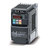
General-purpose Serial, RS-485 Modbus Communication, Multi-function Compact Inverter
Brand:
Omron
| Category:
Inverter
| Size: 3.96 MB
Table of Contents
Table of Contents
5
1 Related Manuals
6
2 Terms and Definitions
7
3 Precautions
8
4 Overview
9
5 Applicable Devices and Device Configuration
10
Applicable Devices
10
Device Configuration
11
6 Serial Communications Settings
13
Parameters
13
Cable Wiring Diagram
14
7 Serial Communications Connection Procedure
15
Work Flow
15
Setting up Inverter
16
Setting up PLC
22
Checking the Serial Communications
36
8 Initialization Method
40
Initializing PLC
40
Initializing Inverter
41
9 Program
42
Overview
42
Destination Device Command
47
Error Detection Processing
49
Memory Maps
50
Ladder Program
53
Timing Chart
59
Error Processing
60
10 Revision History
62
Omron CJ2*-CPU Series Manual (40 pages)
Programmable Automation Controllers
Brand:
Omron
| Category:
Controller
| Size: 8.21 MB
Table of Contents
Key Features and Benefits
3
Data Links
7
System Configuration
16
External Interface
18
General Specifications
19
Performance Specifications
20
International Standards
23
Ordering Information
24
Basic Configuration Units
24
Power Supply Units
24
Programming Devices
26
Basic I/O Units
27
Specifications
27
OMRON CJ2*-CPU Series Datasheet (24 pages)
CJ2 Series PLCs
Brand:
OMRON
| Category:
Controller
| Size: 2.71 MB
Table of Contents
Specifications
10
General Specifications
10
Performance Specifications
10
Ordering Information
16
Advertisement
Related Products
OMRON CJ2H-CPU64 -
OMRON SYSMAC CJ2H-CPU64-EIP
OMRON SYSMAC CJ2H-CPU65-EIP
OMRON SYSMAC CJ2H-CPU66-EIP
OMRON SYSMAC CJ2H-CPU67-EIP
OMRON CJ2H-CPU68-EIP -
Omron CJ2M-CPU11/31
Omron CJ2M-CPU12/32
Omron CJ2M-CPU13/33
Omron CJ2M-CPU14/34
OMRON Categories
Blood Pressure Monitor
Controller
Accessories
Switch
Inverter
More OMRON Manuals
Login
Sign In
OR
Sign in with Facebook
Sign in with Google
Upload manual
Upload from disk
Upload from URL