Table of Contents
Advertisement
Advertisement
Table of Contents

Related Manuals for Omron CJ2-CPU


Summary of Contents for Omron CJ2-CPU
- Page 1 CJ Series IO-Link Connection Guide (EtherNet/IP Host Communications) OMRON Corporation Photoelectric Sensor (E3Z-series IO-Link) [IO-Link Master Unit] OMRON Corporation NX-series IO-Link Master Unit (NX-ILM[][][]) NX-series Ethernet/IP Coupler Unit (NX-EIC202) P666-E1-01...
- Page 2 ODVA and EtherNet/IP are trademarks of ODVA. Sysmac is a trademark or registered trademark of OMRON Corporation in Japan and other countries for OMRON factory automation products. Company names and product names in this document are the trademarks or registered...
-
Page 3: Table Of Contents
Table of Contents Related Manuals ..................1 Terms and Definitions ................2 Precautions ....................4 Overview ....................5 Applicable Devices and Device Configuration ........6 5.1. Applicable Devices ................6 5.2. Device Configuration ................7 Communications Settings ................ 9 6.1. EtherNet/IP Connection Parameters ............9 6.2. -
Page 4: Related Manuals
1.Related Manuals 1. Related Manuals To ensure system safety, make sure to always read and follow the information provided in all Safety Precautions and Precautions for Safe Use in the manuals for each device which is used in the system. The table below lists the manuals which pertain to this document. -
Page 5: Terms And Definitions
In the EtherNet/IP network, a data unit that consists of two or more tags can be exchanged. The data unit consisting of two or more tags for the data exchange is called a tag set. Up to eight tags can be configured per tag set for the programmable controllers produced by OMRON Corporation. - Page 6 2.Terms and Definitions Tag data link In EtherNet/IP, the tag and tag set can be exchanged cyclically between nodes without using a user program. This feature is called a tag data link. Connection A connection is used to exchange data as a unit within which data concurrency is maintained.
-
Page 7: Precautions
(4) It is prohibited to copy, to reproduce, and to distribute a part or the whole of this document without the permission of OMRON Corporation. (5) The information contained in this document is current as of July 2016. It is subject to change for improvement without notice. -
Page 8: Overview
(hereinafter referred to as PLC) via EtherNet/IP through EtherNet/IP Coupler Unit (NX-EIC202) to which IO-Link Master Unit is connected and also for checking their communication status - all of which are produced by OMRON Corporation. Refer to Section 6. Communications Settings and Section 7. IO-Link Connection Procedure to understand setting methods and key points to perform cyclic communications in the IO-Link system. -
Page 9: Applicable Devices And Device Configuration
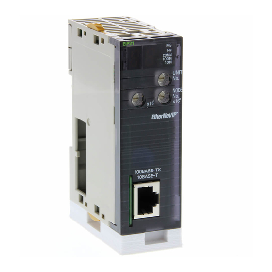
5.Applicable Devices and Device Configuration 5. Applicable Devices and Device Configuration 5.1. Applicable Devices The applicable devices are as follows: Manufacturer Name Model OMRON CJ2 CPU Unit CJ2[]-CPU[][] OMRON EtherNet/IP Unit CJ1W-EIP21 CJ2H-CPU6[]-EIP CJ2M-CPU3[] OMRON NX-series NX-EIC202 EtherNet/IP Coupler Unit... -
Page 10: Device Configuration
USB cable E3Z-D82-IL3 2M Switching hub power supply Unit power supply I/O power supply Manufacturer Name Model Version OMRON CJ2 CPU Unit CJ2M-CPU32 Ver.2.0 (Built-in EtherNet/IP port) (Ver.2.12) OMRON Power Supply Unit CJ1W-PA202 OMRON Switching hub W4S1-05C Ver.1.00... - Page 11 5.Applicable Devices and Device Configuration Precautions for Correct Use Update CX-Programmer and Network Configurator to the versions specified in this Clause 5.2. or to higher versions. If you use a version higher than the one specified, the procedures and related screenshots described in Section 7. and subsequent sections may not be applicable.
-
Page 12: Communications Settings
6.Communications Settings 6. Communications Settings This section describes the contents of the parameter and tag data link settings that are all defined in this document. 6.1. EtherNet/IP Connection Parameters The parameters required for connecting PLC to Slave Terminal via EtherNet/IP are shown below. -
Page 13: Tag Data Link Settings
6.Communications Settings 6.4. Tag Data Link Settings The I/O data (process data) for Photoelectric Sensor are allocated to the tag data links for Slave Terminal. The following shows the content of the tag data link settings for Slave Terminal. Output area Input area D10000 D10100... - Page 14 6.Communications Settings Port 1 Input Data01 0 to 15 <Stores the I/O data for Photoelectric Sensor.> D10104 0 to 7 <Stores Byte0 (PD0).> 8 to 15 <Stores Byte1 (PD1).> D10105 0 to 15 Port 2 Input Data01 D10106 0 to 15 Port 3 Input Data01 D10107 0 to 15...
-
Page 15: Io-Link Connection Procedure
7.IO-Link Connection Procedure 7. IO-Link Connection Procedure This section describes the procedures for connecting Photoelectric Sensor to IO-Link Master Unit via IO-Link and for connecting PLC to Slave Terminal configured of IO-Link Master Unit on the EtherNet/IP network. The explanations of procedures for setting up PLC and Slave Terminal given in this document are based on the factory default settings. - Page 16 7.IO-Link Connection Procedure Set the EtherNet/IP tag data links. 7.4. Network Settings for Host Communications ↓ Start Network Configurator and connect online with 7.4.1. Starting Network Configurator PLC. and Connecting Online with ↓ Upload the network configuration. 7.4.2. Uploading the Network Configuration ↓...
-
Page 17: Slave Terminal Setup
7.IO-Link Connection Procedure 7.2. Slave Terminal Setup Set up Slave Terminal. 7.2.1. Hardware Settings Configure Slave Terminal, set hardware switches, and connect Photoelectric Sensor. Precautions for Correct Use Make sure that the power supply is OFF when you set up. Make sure that EtherNet/IP Coupler Unit and IO-Link Master Unit are powered OFF. - Page 18 7.IO-Link Connection Procedure Check that Dip switch is set as follows: SW3 NET: OFF SW4 ADR: OFF *The tag data links become enabled, and the first to third octets of the IP address are set to 192.168.250. *The forth octet of the IP address is set by Rotary Name Meaning...
- Page 19 7.IO-Link Connection Procedure Connect Unit power supply and I/O power supply to Unit power Unit power supply terminals supply terminals and I/O power supply terminals on EtherNet/IP Coupler Unit, respectively. Unit power supply *For connecting the power supplies for NX-series Slave Terminals, refer to NX-series EtherNet/IP Coupler Unit...
- Page 20 7.IO-Link Connection Procedure 7.2.2. Starting Sysmac Studio and Connecting Online with Slave Terminal Start Sysmac Studio and connect online with Slave Terminal. Install Sysmac Studio and the USB driver on Personal computer beforehand. Connect the peripheral USB Personal computer Slave Terminal port on Slave Terminal to Peripheral (USB) port...
- Page 21 7.IO-Link Connection Procedure The New Project is displayed. The following panes are displayed in this window. Left: Multiview Explorer Top right: Toolbox Top middle: Edit Configuration Multiview Edit Toolbox Explorer Configuration Pane Pane The following tabs are displayed in the bottom middle of this window.
- Page 22 7.IO-Link Connection Procedure 7.2.3. Setting the Slave Terminal Configuration Information Set the Slave Terminal configuration information. Right-click the device icon of EtherNet/IP Coupler Unit (Unit 0) and select Compare and Merge with Actual Unit Configuration. The Compare and Merge with Actual Unit Configuration Dialog Box is displayed.
- Page 23 7.IO-Link Connection Procedure The IO-Link Master Unit is added next to EtherNet/IP Check the added unit. Coupler Unit on the EIP : NX-EIC202 (Master) Tab Page. Select the device icon of EtherNet/IP Coupler Unit (Unit 0) and click Offline. Select Check that EtherNet/IP Coupler Unit goes Offline.
- Page 24 7.IO-Link Connection Procedure 7.2.4. IO-Link Master Unit Setup Set the parameters for IO-Link Master Unit. In this document, the default values are used for the parameter settings of IO-Link Master Unit. Check that IO-Link Mode is set as the communications mode for Port 1 to which Photoelectric Sensor is connected.
- Page 25 7.IO-Link Connection Procedure A list of Port1 IO-Link Device Configuration Data is displayed. Check that IO-Link Mode is selected as the set value of Port1 IO-Link Device Configuration Data/Master Control. *If IO-Link Mode is not displayed in the Value Column, select the mode from the pull-down list.
- Page 26 7.IO-Link Connection Procedure 7.2.5. I/O Allocation Settings Set the I/O allocations for IO-Link Master Unit. As the default values are used for the I/O allocations in this document, the I/O allocation settings are made without editing any of the values. Additional Information To save the I/O data size for unused ports, delete the I/O...
- Page 27 7.IO-Link Connection Procedure 7.2.6. Transferring the Setting Data Transfer the setting data of Slave Terminal to EtherNet/IP Coupler Unit. Select the device icon of EtherNet/IP Coupler Unit on the EIP : NX-EIC202(Master) Tab Page in the Edit Configuration Pane, and connect online with EtherNet/IP Coupler Unit in the same way as steps 8 to 10 in 7.2.2.
- Page 28 7.IO-Link Connection Procedure Select the device icon of EtherNet/IP Coupler Unit (Unit 0) and click Offline. Check that EtherNet/IP Coupler Unit goes offline. Select Exit from the File Menu to close Sysmac Studio. The dialog box on the right is displayed.
-
Page 29: Plc Setup
7.IO-Link Connection Procedure 7.3. PLC Setup Set up PLC. 7.3.1. Hardware Settings Set the hardware switches on EtherNet/IP Unit and wire the network. Precautions for Correct Use Make sure that the power supply is OFF when you set up. Make sure that PLC and Switching hub are powered OFF. - Page 30 7.IO-Link Connection Procedure Connect a LAN cable to the Personal computer Switching hub EtherNet/IP port on PLC, and connect a USB cable to the USB LAN cable USB cable port. As shown in 5.2. Device LAN cable Configuration, connect Personal computer and Switching Hub to USB cable Slave Terminal...
- Page 31 7.IO-Link Connection Procedure 7.3.2. Starting CX-Programmer and Connecting Online with PLC Start CX-Programmer and connect online with PLC. Install CX-One and the USB driver on Personal computer beforehand. Start CX-Programmer. *If the User Account Control Dialog Box is displayed at start, make a selection to start CX-Programmer.
- Page 32 7.IO-Link Connection Procedure The dialog box on the right is displayed. Check the contents and click No. The dialog box on the right is displayed. CX-Programmer and PLC are automatically connected. Check that CX-Programmer and PLC are connected online. *The icon is pressed down during online connection.
- Page 33 7.IO-Link Connection Procedure 7.3.3. Creating the I/O Table and Setting the IP Address Create the I/O table and set the IP address of PLC. If the operating mode of PLC is Run Mode or Monitor Mode, change it to Program Mode by following the steps below.
- Page 34 7.IO-Link Connection Procedure Precautions for Correct Use The PLC is reset after creating and transferring the I/O table in step 3 and subsequent steps. Always confirm safety before creating and transferring the I/O table. Select Create from the Options Menu in the PLC IO Table Window.
- Page 35 7.IO-Link Connection Procedure The Transfer from PLC Dialog Box is displayed. Select IO Table and SIO Unit Parameters. Click Transfer. When the transfer is completed, the Transfer Results Dialog Box is displayed. Check that the transfer is successfully completed by referring to the message in the dialog box.
- Page 36 7.IO-Link Connection Procedure In the PLC IO Table Window, click + to the left of Built-in Port/Inner Board to display CJ2M-EIP21. *The figure on the right displays CPU Unit (Built-in EtherNet/IP port) specified in 5.2. Device Configuration. If you use an other applicable EtherNet/IP Unit, the display position and name are different from the...
- Page 37 7.IO-Link Connection Procedure The dialog box on the right is displayed. Confirm that there is no problem, and click Yes. Check that a message is displayed stating "Transfer successful". Click Close. The dialog box on the right is displayed. Check the contents and click Yes.
- Page 38 7.IO-Link Connection Procedure Click Compare to check that the IP address is correctly changed. Check that a message is displayed stating "Compare successful". Click Close. Click OK in the Edit Parameters Dialog Box.
-
Page 39: Network Settings For Host Communications
7.IO-Link Connection Procedure 7.4. Network Settings for Host Communications Set the EtherNet/IP tag data links. 7.4.1. Starting Network Configurator and Connecting Online with PLC Start Network Configurator and connect online with PLC. Right-click CJ2M-EIP21 in the PLC IO Table Window, and select Start Special Application - Start with Settings Inherited. - Page 40 7.IO-Link Connection Procedure Precautions for Correct Use Check that the LAN cables are connected before performing the following steps. If they are not connected, turn OFF each of the devices, and then connect the LAN cables. Select Select Interface - CJ2 USB/Serial Port from the Option Menu.
- Page 41 7.IO-Link Connection Procedure The Select Connected Network Dialog Box is displayed. Check the contents and click When an online connection is established normally, the color of the icon changes to blue as shown on the right. Additional Information If PLC cannot be connected online, check the cable connection. Or, return to step 3, check the settings and repeat each step.
- Page 42 7.IO-Link Connection Procedure 7.4.2. Uploading the Network Configuration Upload the network configuration. Select Upload from the Network Menu to upload the device information on the network. The dialog box on the right is displayed. Confirm that there is no problem, and click Yes. The Target Device Dialog Box is displayed.
- Page 43 7.IO-Link Connection Procedure Check that the uploaded nodes with the following IP addresses are configured in the Network Configuration Pane. IP address of node 1: 192.168.250.1 IP address of node 2: 192.168.250.2...
- Page 44 7.IO-Link Connection Procedure 7.4.3. Setting the Tags Register tags for input (consume) and output (produce). The following explains the receive and send settings of the target device in order. In the Network Configuration Pane of Network Configurator, right-click the node 1 device and select Parameter - Edit.
- Page 45 7.IO-Link Connection Procedure The Edit Tags Dialog Box is displayed. Select the In - Consume Tab and click New. Here, register a tag for the area where the node 1 consumes data from the node 2. The Edit Tag Dialog Box is displayed.
- Page 46 7.IO-Link Connection Procedure Select the Out - Produce Tab and click New. Here, register a tag for the area where the node 1 produces data to the node 2. The Edit Tag Dialog Box is displayed. Enter the following values of the parameters. Name: D10000 (Start address of the output data from node Size: 8 (Byte)
- Page 47 7.IO-Link Connection Procedure When you finish the registration, click OK in the Edit Tags Dialog Box. The dialog box on the right is displayed. Confirm that there is no problem, and click Yes. The Edit Device Parameters Dialog Box is displayed again. Select the Connections Tab.
- Page 48 7.IO-Link Connection Procedure 7.4.4. Setting the Connections Associate the tags of the target device (that receives the open request) with the tags of the originator device (that requests for opening). Select 192.168.250.2 in the Unregister Device List Field. Click the Down Arrow Button that is shown in the dialog box.
- Page 49 7.IO-Link Connection Procedure Check that the settings are correct. Click Regist. The Edit Connection Dialog Box is displayed again. Click Close. The Edit Device Parameters Dialog Box is displayed again. Click OK. When the connection is completed, the registered node address is displayed under the device icon of node 2 in the Network Configuration Pane.
- Page 50 7.IO-Link Connection Procedure 7.4.5. Transferring the Tag Data Link Parameters Transfer the set tag data link parameters to PLC. Right-click the device icon of node 1 in the Network Configuration Pane and select Parameter – Download from the menu. The dialog box on the right is displayed.
-
Page 51: Io-Link Communication Status Check
7.IO-Link Connection Procedure 7.5. IO-Link Communication Status Check Confirm that cyclic communications in the IO-Link system performs normally. 7.5.1. Checking the Connection Status Check the connection status of each device. Turn ON I/O power supply for Slave Terminal. Check with LED indicators on PLC (EtherNet/IP Unit) that the EtherNet/IP tag data links operate normally. - Page 52 7.IO-Link Connection Procedure Check the LED indicator on Photoelectric Sensor. Stability indicator/ The LED indicator in normal status IO-Link Communication indicator is as follows: <Top view of Photoelectric Sensor> Stability indicator / IO-Link Communication indicator: Green flashing (1sec cycle) The normal operation of tag data links is confirmed through the status information in the Monitor Device Dialog Box of Network Configurator.
- Page 53 7.IO-Link Connection Procedure Select Disconnect from the Network Menu to go offline. The color of the icon changes from blue to gray as shown on the right. Select Exit from the File Menu to close Network Configurator. A confirmation dialog box is displayed whether or not you save the changed network configuration.
- Page 54 7.IO-Link Connection Procedure 7.5.2. Checking the Receive Data Check that the correct data are received. Check that CX-ConfiguratorFDT is being installed on Personal computer. CX-ConfiguratorFDT is included in Sysmac Studio. If you wire the I/O in the state where the devices are powered ON, doing so may cause damage to the devices.
- Page 55 7.IO-Link Connection Procedure The PLC Memory Window is displayed. Double-click D on the Memory Tab of the PLC Memory Window. Select Display - Hexadecimal from the View Menu. Select Monitor from the Online Menu. The Monitor Memory Areas Dialog Box is displayed. Check that D is selected.
- Page 56 7.IO-Link Connection Procedure CX-ConfiguratorFDT starts. Right-click MyNetwork in the Network View and select Add from the menu. The Add Dialog Box is displayed. Select NX Coupler USB. Click OK. Check that <NX bus> NX Coupler USB is added under MyNetwork in the Network View.
- Page 57 7.IO-Link Connection Procedure Right-click <NX bus> NX Coupler USB and select Scan - Create Network from the menu. The Lifelist Dialog Box is displayed after completing the network scan. Check that <IO-Link Port_1:NOT_APPLICABLE> E3Z-D-IL3 IODD1.1 is added under NX-ILM400. Click Add All and Continue.
- Page 58 7.IO-Link Connection Procedure Check that the network configuration is created in the Network View as shown on the right. Right-click <IO-Link Port_1:-> E3Z-D-IL3 IODD1.1 and select Go online from the menu. Check that Photoelectric Sensor is connected online. Right-click <IO-Link Port_1:-> E3Z-D-IL3 IODD1.1 and select Configuration from the menu.
- Page 59 7.IO-Link Connection Procedure Select Observation listed under Menu on the <IO-Link Port_1:-> E3Z-D-IL3 IODD1.1 - Configuration Tab Page. If Process Data In on the right side of the tab page is not expanded, click the + Button of Process Data In to expand.
- Page 60 7.IO-Link Connection Procedure In the PLC Memory Window of CX-Programmer, check that the value of D10104 is as shown below. D10104 Bits 0 to 7: 4 (dec) Bits 8 and 9: 00 (bin) *For details on each of the D10104 addresses, refer to 6.4.
- Page 61 7.IO-Link Connection Procedure In the PLC Memory Window of CX-Programmer, check that the value of D10104 is as shown below. D10104 Bits 0 to 7: 255 (dec) Bits 8 and 9: 11 (bin) *For details on each of the D10104 addresses, refer to 6.4.
-
Page 62: Initialization Method
8.Initialization Method 8. Initialization Method The setting procedures in this document are based on the factory default settings. Some settings may not be applicable unless you use the devices with the factory default settings. 8.1. Initializing PLC To initialize the PLC settings, it is necessary to initialize EtherNet/IP Unit and CPU Unit. Change the operating mode of PLC to PROGRAM mode before the initialization. - Page 63 8.Initialization Method (3)An execution confirmation dialog box is displayed. Confirm that there is no problem, and click Yes. (4)The Restart Unit Dialog Box is displayed. Select Return to out-of-box configuration, and then emulate cycling power, and click OK. (5)A dialog box is displayed indicating that the execution is completed. Check the contents and click OK.
-
Page 64: Initializing Slave Terminal
8.Initialization Method 8.2. Initializing Slave Terminal To initialize the Slave Terminal settings, connect Sysmac Studio online with Slave Terminal and take the following steps. (1)Right-click the device icon of EtherNet/IP Coupler Unit (Unit 0). Select Clear All Memory from the menu. (2)The Clear All Memory for Coupler Dialog Box is displayed. -
Page 65: Initializing Photoelectric Sensor
8.Initialization Method Precautions for Correct Use In the initialization of Slave Terminal, the backup data for the IO-Link devices that is stored in IO-Link Master Unit is not cleared. If you need to clear the backup data stored in IO-Link Master Unit, refer to Clearing Backup Data in 7-4-2 Backing Up Settings of the IO-Link System User's Manual (Cat. -
Page 66: Revision History
9.Revision History 9. Revision History Revision Date of revision Description of revision code August 8, 2016 First edition... - Page 68 2016 P666-E1-01 0 16-(-)