Sign In
Upload
Manuals
Brands
Juniper Manuals
Gateway
SRX345
Juniper SRX345 Security Appliance Manuals
Manuals and User Guides for Juniper SRX345 Security Appliance. We have
8
Juniper SRX345 Security Appliance manuals available for free PDF download: Hardware Manual, User Manual, Quick Start Manual, How To Set Up, Manual
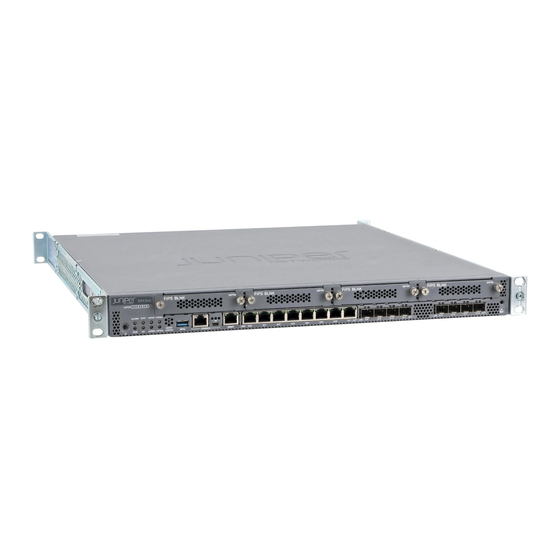
Juniper SRX345 Hardware Manual (154 pages)
Brand:
Juniper
| Category:
Gateway
| Size: 2.52 MB
Table of Contents
Table of Contents
3
About the Documentation
11
Documentation and Release Notes
11
Supported Platforms
11
Documentation Conventions
11
Table 1: Notice Icons
12
Table 2: Text and Syntax Conventions
12
Documentation Feedback
13
About the Documentation
13
Requesting Technical Support
14
Self-Help Online Tools and Resources
14
Opening a Case with JTAC
14
Overview
17
System Overview
17
Chassis Description
17
Chapter 1 System Overview
19
System Overview
19
SRX345 Services Gateway Description
19
Chapter 2 Chassis Description
21
Chassis Description
21
SRX345 Services Gateway Chassis Overview
21
Understanding the SRX345 Services Gateway Front Panel
21
Figure 2: SRX345 Services Gateway (Single AC Power Supply) Front Panel
22
Figure 3: SRX345 Services Gateway (Dual AC Power Supplies) Front Panel
22
Table 3: SRX345 Services Gateway Front Panel Components
22
Chassis Description
23
Figure 4: SRX345 Services Gateway Front Panel Leds
23
Table 4: SRX345 Services Gateway Front Panel Leds
23
Figure 5: SRX345 Services Gateway Back Panel (Single AC Power Supply)
24
Figure 6: SRX345 Services Gateway Back Panel (Dual AC Power Supplies)
24
Understanding the SRX345 Services Gateway Back Panel
24
Table 5: SRX345 Services Gateway Back Panel Components
25
Table 6: SRX345 Services Gateway (with Dual AC Power Supplies) Back Panel
25
Chapter 3 Interface Module Descriptions
27
Interface Module Descriptions
27
SRX345 Services Gateway Interface Modules Overview
27
Chapter 4 Cooling System Description
29
Cooling System Description
29
Understanding the SRX345 Services Gateway Cooling System
29
Figure 7: Airflow through the SRX345 Services Gateway Chassis
29
Chapter 5 Power System Description
31
Understanding the SRX345 Services Gateway Power Supply
31
Chapter 6 Planning and Preparing the Site
33
Site Planning and Specifications
33
Planning and Preparing the Site
35
SRX345 Services Gateway Physical Specifications
35
SRX345 Services Gateway Environmental Specifications
35
Table 7: Physical Specifications for the SRX345 Services Gateway
35
Site Preparation Checklist for the SRX345 Services Gateway
36
Table 8: Environmental Specifications for the SRX345 Services Gateway
36
Table 9: Site Preparation Checklist for SRX345 Services Gateway
36
General Site Installation Guidelines for the SRX345 Services Gateway
38
Chapter 7 Rack Requirements
41
SRX345 Services Gateway Rack Size and Strength Requirements
45
SRX345 Services Gateway Spacing of Mounting Brackets and Flange Holes
45
SRX345 Services Gateway Clearance Requirements for Airflow and Hardware
46
Maintenance
46
Rack Requirements
41
SRX345 Services Gateway Rack-Mounting Requirements and Warnings
41
Cabinet Requirements
47
SRX345 Services Gateway Cabinet Size and Clearance Requirements
47
SRX345 Services Gateway Cabinet Airflow Requirements
47
Chapter 8 Cabinet Requirements
47
Chapter 9 Power Requirements and Specifications
49
SRX345 Services Gateway Electrical Wiring Guidelines
49
Table 10: Site Electrical Wiring Guidelines for the SRX345 Services Gateway
49
SRX345 Services Gateway Power Specifications and Requirements
50
Table 11: Power System Electrical Specifications for the SRX345 Services
50
SRX345 Services Gateway Supported AC Power Cords
51
Figure 8: AC Plug Types
51
Power Requirements and Specifications
51
Table 12: AC Power Cord Specifications
51
Chapter 10 Cable Specifications and Pinouts
53
RJ-45 Connector Pinouts for the SRX345 Services Gateway Ethernet Port
53
RJ-45 Connector Pinouts for the SRX345 Services Gateway Console Port
53
Mini-USB Connector Pinouts for the SRX345 Services Gateway Console Port
54
Table 14: RJ-45 Connector Pinouts for the SRX345 Services Gateway Console
54
Table 15: Mini-USB Type-B Connector Pinouts for the Services Gateway Console
54
Initial Installation and Configuration
57
Installation
57
Chapter 11 Installation Overview
59
SRX345 Services Gateway Autoinstallation Overview
60
Installation Overview
59
SRX345 Services Gateway Installation Overview
59
Required Tools and Parts for Installing the SRX345 Services Gateway
59
Chapter 12 Unpacking the SRX345 Services Gateway
61
Verifying Parts Received with the SRX345 Services Gateway
62
Table 16: Parts List for a Fully Configured SRX345 Services Gateway
62
Table 17: Accessory Parts List for the SRX345 Services Gateway
63
Chapter 13 Installing the Rack Mounting Hardware
65
Installing the Rack Mounting Hardware
65
Preparing the SRX345 Services Gateway for Rack-Mount Installation
65
Connecting the SRX345 Services Gateway to the Building Structure
65
Figure 1: SRX345 Services Gateway
65
Chapter 14 Installing the SRX345 Services Gateway in a Rack
67
Installing the SRX345 Services Gateway into a Rack
67
Figure 9: Installing the Rack Mount Brackets (Front Mount Position)
67
Figure 10: Installing the Rack Mount Brackets (Center Mount Position)
68
Figure 11: Installing the Services Gateway in the Rack (Front Mount Shown, Center Mount Similar)
68
Chapter 15 Connecting the SRX345 Services Gateway to Ground
71
Required Tools and Parts for Grounding the SRX345 Services Gateway
71
SRX345 Services Gateway Grounding Specifications
71
Connecting the SRX345 Services Gateway Grounding Cable
72
Figure 12: Connecting the Grounding Cable to the SRX345 Services Gateway
73
Chapter 16 Connecting the SRX345 Services Gateway to External Devices
75
Gateway
75
Connecting to the SRX345 Services Gateway CLI Using a Dial-Up Modem
76
Chapter 17 Providing Power to the SRX345 Services Gateway
79
Connecting the SRX345 Services Gateway to an AC Power Supply
79
Powering on the SRX345 Services Gateway
80
Figure 13: Connecting the SRX345 Services Gateway to an AC Power Supply
80
Powering off the SRX345 Services Gateway
81
Chapter 18 Performing the Initial Configuration
83
SRX345 Services Gateway Software Configuration Overview
83
Understanding SRX345 Services Gateway Factory-Default Settings
84
Viewing SRX345 Services Gateway Factory-Default Settings
85
Configuring Zero-Touch Provisioning on the SRX345 Services Gateway
86
Accessing J-Web on the SRX345 Services Gateway
87
Configuring the SRX345 Services Gateway Using the J-Web Setup Wizard
88
Figure 14: Connecting to the Management Port on the SRX345 Services
88
About the Default Setup Mode
89
About the Setup Wizard
89
About the Guided Setup Mode
90
Accessing the CLI on the SRX345 Services Gateway
92
Connecting to the SRX345 Services Gateway from the CLI Remotely
93
Figure 15: Connecting to the Console Port on the SRX345 Services Gateway
93
Configuring the SRX345 Services Gateway Using the CLI
94
Maintaining and Troubleshooting Components
99
Chapter 19 Maintaining Components
101
Maintaining the SRX345 Services Gateway Cooling System Components
102
Maintaining the SRX345 Services Gateway Power Supply
102
Maintaining Components
101
Required Tools and Parts for Maintaining the SRX345 Services Gateway Hardware Components
101
Routine Maintenance Procedures for the SRX345 Services Gateway
101
Chapter 20 Troubleshooting Components
105
Troubleshooting Chassis and Interface Alarm Messages on the SRX345 Services
106
Gateway
106
Troubleshooting the Power System on the SRX345 Services Gateway
107
Using the RESET CONFIG Button on the SRX345 Services Gateway
108
Changing the RESET CONFIG Button Behavior on the SRX345 Services Gateway
109
Gateway
109
Documentation Gateway
109
Troubleshooting the Power System on the SRX345 Services Gateway
109
Using the RESET CONFIG Button on the SRX345 Services Gateway
110
Troubleshooting Components
105
Troubleshooting Resources for the SRX345 Services Gateway Overview
105
Leds
105
Part 5 Replacing Components
111
Replacing Components
111
Chapter 21 Overview of Replacing Components
113
SRX345 Services Gateway Field Replaceable Units Overview
113
Required Tools and Parts for Replacing the SRX345 Services Gateway
113
Components
113
Chapter 22 Replacing Interface Modules
115
Replacing Mini-Physical Interface Modules in the SRX345 Services Gateway
115
Chapter 23 Contacting Customer Support and Returning Components
117
Returning a SRX345 Services Gateway Component to Juniper Networks
118
Locating the SRX345 Services Gateway Chassis Serial Number and Agency
119
Labels
119
Locating the SRX345 Services Gateway Mini-Physical Interface Module Serial
119
Number Label
119
Listing the SRX345 Services Gateway Component Details with the CLI
120
Information You Might Need to Supply to JTAC
120
Required Tools and Parts for Packing the SRX345 Services Gateway
121
Packing the SRX345 Services Gateway for Shipment
122
Packing SRX345 Services Gateway Components for Shipment
123
Part 6 Safety and Regulatory Compliance Information
125
Contacting Customer Support and Returning Components
117
Contacting Customer Support
117
Chapter 24 General Safety Guidelines and Warnings
127
Definitions of Safety Warning Levels
127
General Safety Guidelines and Warnings
129
Restricted Access Warning
130
Qualified Personnel Warning
131
Prevention of Electrostatic Discharge Damage
132
Figure 16: Placing a Component into an Antistatic Bag
133
Chapter 25 Firesafetyrequirements
135
Fire Safety Requirements
135
Chapter 26 Laser and LED Safety Guidelines and Warnings
137
General Laser Safety Guidelines
137
Class 1 Laser Product Warning
138
Class 1 LED Product Warning
138
Laser Beam Warning
138
Radiation from Open Port Apertures Warning
139
Chapter 27 Maintenanceandoperationalsafetyguidelinesandwarnings
141
Maintenance and Operational Safety Guidelines and Warnings
141
Battery Handling Warning
141
Jewelry Removal Warning
142
Lightning Activity Warning
143
Operating Temperature Warning
144
Product Disposal Warning
145
Chapter 28 Electrical Safety Guidelines and Warnings
147
Action to Take after an Electrical Accident
147
General Electrical Safety Guidelines and Warnings
147
AC Power Electrical Safety Guidelines
148
Advertisement
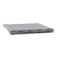
Juniper SRX345 Hardware Manual (150 pages)
Services Gateway
Brand:
Juniper
| Category:
Gateway
| Size: 2.36 MB
Table of Contents
Table of Contents
3
List of Figures
9
About the Documentation
13
Documentation and Release Notes
13
Documentation Conventions
13
Supported Platforms
13
Table 1: Notice Icons
14
Table 2: Text and Syntax Conventions
14
Documentation Feedback
15
About the Documentation
15
Opening a Case with JTAC
16
Requesting Technical Support
16
Self-Help Online Tools and Resources
16
Overview
19
Chassis Description
19
Cooling System Description
19
Chapter 1 System Overview
21
System Overview
21
Gateway
21
SRX340 Services Gateway CLI and J-Web Access
21
SRX340 Services Gateway Description
21
Chassis Description
23
SRX340 Services Gateway Chassis Overview
23
Understanding the SRX340 Services Gateway Front Panel
23
Chapter 2 Chassis Description
23
Figure 1: SRX340 Services Gateway Front Panel
24
Table 3: SRX340 Services Gateway Front Panel Components
24
Chassis Description
25
Figure 2: SRX340 Services Gateway Front Panel Leds
25
Table 4: SRX340 Services Gateway Front Panel Leds
25
Figure 3: SRX340 Services Gateway Back Panel
26
Table 5: SRX340 Services Gateway Back Panel Components
26
Understanding the SRX340 Services Gateway Back Panel
26
Chapter 3 Interface Module Descriptions
29
SRX340 Services Gateway Interface Modules Overview
29
Chapter 4 Cooling System Description
31
Understanding the SRX340 Services Gateway Cooling System
31
Figure 4: Airflow through the SRX340 Services Gateway Chassis
31
Chapter 5 Power System Description
33
Understanding the SRX340 Services Gateway Power Supply
33
Chapter 6 Planning and Preparing the Site
35
Planning and Preparing the Site
37
SRX340 Services Gateway Physical Specifications
37
SRX340 Services Gateway Environmental Specifications
37
Table 6: Physical Specifications for the SRX340 Services Gateway
37
Table 7: Environmental Specifications for the SRX340 Services Gateway
37
Site Preparation Checklist for the SRX340 Services Gateway
38
Table 8: Site Preparation Checklist for SRX340 Services Gateway
38
General Site Installation Guidelines for the SRX340 Services Gateway
40
Site Planning and Specifications
35
Power Requirements and Specifications
35
Rack Requirements
43
SRX340 Services Gateway Rack-Mounting Requirements and Warnings
43
Chapter 7 Rack Requirements
43
SRX340 Services Gateway Rack Size and Strength Requirements
47
SRX340 Services Gateway Spacing of Mounting Brackets and Flange Holes
47
SRX340 Services Gateway Clearance Requirements for Airflow and Hardware
48
Maintenance
48
Cabinet Requirements
49
SRX340 Services Gateway Cabinet Airflow Requirements
49
SRX340 Services Gateway Cabinet Size and Clearance Requirements
49
Chapter 8 Cabinet Requirements
49
Chapter 9 Power Requirements and Specifications
51
SRX340 Services Gateway Electrical Wiring Guidelines
51
Table 9: Site Electrical Wiring Guidelines for the SRX340 Services Gateway
51
SRX340 Services Gateway Power Specifications and Requirements
52
Table 10: Power System Electrical Specifications for the SRX340 Services
52
SRX340 Services Gateway Supported AC Power Cords
53
Figure 5: AC Plug Types
53
Power Requirements and Specifications
53
Table 11: AC Power Cord Specifications
53
Chapter 10 Cable Specifications and Pinouts
55
RJ-45 Connector Pinouts for the SRX340 Services Gateway Ethernet Port
55
RJ-45 Connector Pinouts for the SRX340 Services Gateway Console Port
55
Mini-USB Connector Pinouts for the SRX340 Services Gateway Console
56
Port
56
Table 13: RJ-45 Connector Pinouts for the SRX340 Services Gateway Console
56
Table 14: Mini-USB Type-B Connector Pinouts for the Services Gateway Console
56
Cable Specifications and Pinouts
57
Initial Installation and Configuration
59
Installation Overview
61
Required Tools and Parts for Installing the SRX340 Services Gateway
61
SRX340 Services Gateway Installation Overview
61
Chapter 11 Installation Overview
61
SRX340 Services Gateway Autoinstallation Overview
62
Chapter 12 Unpacking the SRX340 Services Gateway
63
Verifying Parts Received with the SRX340 Services Gateway
64
Table 15: Parts List for a Fully Configured SRX340 Services Gateway
64
Table 16: Accessory Parts List for the SRX340 Services Gateway
64
Chapter 13 Installing the Rack Mounting Hardware
67
Preparing the SRX340 Services Gateway for Rack-Mount Installation
67
Connecting the SRX340 Services Gateway to the Building Structure
67
Chapter 14 Installingthesrx340Servicesgatewayinarack
69
Figure 6: Installing the Rack Mount Brackets (Front Mount Position)
69
Installing the SRX340 Services Gateway in a Rack
69
Figure 7: Installing the Rack Mount Brackets (Center Mount Position)
70
Figure 8: Installing the Services Gateway in the Rack (Front Mount Shown, Center Mount Similar)
70
Chapter 15 Connecting the SRX340 Services Gateway to Ground
71
Required Tools and Parts for Grounding the SRX340 Services Gateway
71
SRX340 Services Gateway Grounding Specifications
71
Connecting the SRX340 Services Gateway Grounding Cable
72
Table 17: Grounding Cable Specifications for the Services Gateway
72
Figure 9: Connecting the Grounding Cable to the SRX340 Services Gateway
73
Chapter 16 Connecting the SRX340 Services Gateway to External Devices
75
Gateway
75
Connecting to the SRX340 Services Gateway CLI Using a Dial-Up Modem
76
Chapter 17 Providing Power to the SRX340 Services Gateway
77
Connecting the SRX340 Services Gateway to an AC Power Supply
77
Powering on the SRX340 Services Gateway
78
Powering off the SRX340 Services Gateway
78
Chapter 18 Performing the Initial Configuration
81
SRX340 Services Gateway Software Configuration Overview
81
Understanding SRX340 Services Gateway Factory-Default Settings
82
Viewing SRX340 Services Gateway Factory-Default Settings
82
Accessing J-Web on the SRX340 Services Gateway
84
Figure 11: Connecting to the Management Port on the SRX340 Services
84
Configuring the SRX340 Services Gateway Using the J-Web Setup Wizard
85
About the Setup Wizard
85
About the Default Setup Mode
86
About the Guided Setup Mode
86
Accessing the CLI on the SRX340 Services Gateway
87
Figure 12: Connecting to the Console Port on the SRX340 Services Gateway
88
Connecting to the SRX340 Services Gateway from the CLI Remotely
89
Configuring the SRX340 Services Gateway Using the CLI
89
Maintaining and Troubleshooting Components
93
Maintaining Components
95
Required Tools and Parts for Maintaining the SRX340 Services Gateway Hardware Components
95
Routine Maintenance Procedures for the SRX340 Services Gateway
95
Chapter 19 Maintaining Components
95
Maintaining the SRX340 Services Gateway Cooling System Components
96
Maintaining the SRX340 Services Gateway Power Supply
96
Troubleshooting Components
97
Chapter 20 Troubleshooting Components
97
Troubleshooting Components
97
Troubleshooting Resources for the SRX340 Services Gateway Overview
97
Troubleshooting Chassis and Interface Alarm Messages on the SRX340 Services
98
Gateway
98
Troubleshooting the Power System on the SRX340 Services Gateway
99
Using the RESET CONFIG Button on the SRX340 Services Gateway
99
Gateway
100
Gateway
101
Using the RESET CONFIG Button on the SRX340 Services Gateway
100
Replacing Components
103
Part 5 Replacing Components
103
Chapter 21 Overview of Replacing Components
105
SRX340 Services Gateway Field Replaceable Units Overview
105
Required Tools and Parts for Replacing the SRX340 Services Gateway
105
Components
105
Chapter 22 Replacing Interface Modules
107
Replacing Mini-Physical Interface Modules in the SRX340 Services Gateway
107
Contacting Customer Support and Returning Components
109
Contacting Customer Support
109
Chapter 23 Contacting Customer Support and Returning Components
109
Returning a SRX340 Services Gateway Component to Juniper Networks
110
Locating the SRX340 Services Gateway Chassis Serial Number and Agency
111
Labels
111
Locating the SRX340 Services Gateway Mini-Physical Interface Module Serial
111
Listing the SRX340 Services Gateway Component Details with the CLI
111
Number Label
111
Information You Might Need to Supply to JTAC
112
Packing the SRX340 Services Gateway for Shipment
113
Required Tools and Parts for Packing the SRX340 Services Gateway
113
Packing SRX340 Services Gateway Components for Shipment
114
Part 6 Safety and Regulatory Compliance Information
117
Chapter 24 General Safety Guidelines and Warnings
119
SRX340 Services Gateway Definition of Safety Warning Levels
119
SRX340 Services Gateway General Safety Guidelines and Warnings
121
Installation
121
SRX340 Services Gateway Safety Requirements, Warnings, and Guidelines
122
Restricted Access Area Warning
122
Qualified Personnel Warning
124
Figure 13: Placing a Component into an Electrostatic Bag
125
Gateway
125
Chapter 25 Fire Safety Requirements
127
SRX340 Services Gateway Fire Safety Requirements and Fire Suppression
127
Equipment
127
Chapter 26 Laser and LED Safety Guidelines and Warnings
129
General Laser Safety Guidelines
129
Class 1 Laser Warning
130
Class 1 LED Product Warning
130
Laser Beam Warning
131
Radiation from Open Port Apertures Warning
132
Chapter 27 Maintenance and Operational Safety Guidelines and Warnings
133
Battery-Handling Warning
133
Lightning Activity Warning
134
Jewelry Removal Warning
135
Operating Temperature Warning
136
Product Disposal Warning
138
Chapter 28 Electrical Safety Guidelines and Warnings
139
In Case of Electrical Accident
139
General Electrical Safety Guidelines and Warnings
139
AC Power Electrical Safety Guidelines
140
Chapter 29 Agency Approvals and Regulatory Compliance Information
143
SRX340 Services Gateway Agency Approvals
143
SRX340 Services Gateway Acoustic Noise Compliance Statements
144
SRX340 Services Gateway EMC Requirements
145
Canada
145
European Community
145
Israel
145
Japan
145
United States
145
Index
149
Juniper SRX345 User Manual (128 pages)
High Memory Gateway Interface Modules Reference
Brand:
Juniper
| Category:
Network Hardware
| Size: 1.91 MB
Table of Contents
Table of Contents
3
About the Documentation
13
Documentation and Release Notes
13
Documentation Conventions
13
Supported Platforms
13
Table 1: Notice Icons
14
Table 2: Text and Syntax Conventions
14
About the Documentation
15
Documentation Feedback
15
Opening a Case with JTAC
16
Requesting Technical Support
16
Self-Help Online Tools and Resources
16
Chapter 1 SRX Series Services Gateway Interface Modules Support
19
Overview
19
Srx Series Services Gateway Interface Modules Support
21
Overview
21
SRX300 Series and SRX550 High Memory Services Gateway Interface
21
SRX300 Series and SRX550 High Memory Services Gateway Gigabit-Backplane Physical Interface Modules Overview
22
SRX300 Series and SRX550 High Memory Services Gateway Mini-Physical Interface Modules Overview
22
Table 3: SRX300 Series and SRX550 High Memory Services Gateway Mini-PIM
22
Figure 1: SRX550 High Memory Services Gateway Slot Numbers
23
Figure 2: Example of a Standard GPIM (Installs in One Standard Slot)
23
Table 4: SRX550 High Memory Services Gateway GPIM/XPIM Model
23
Figure 3: Example of a Double-High, Single-Wide XPIM
24
Interfaces Port Naming Conventions for the SRX300 Series and SRX550 High Memory Services Gateways
24
Table 5: Interface Port Number Examples
24
SRX300 Series and SRX550 High Memory Services Gateway Interface Modules and Compatibility
25
MTU Default and Maximum Values for Physical Interface Modules
26
Table 6: Mini-PIM Types and Hardware Platform Compatibility
26
Table 7: XPIM Types and Hardware Platform Compatibility
26
Table 8: MTU Terms
27
Table 9: MTU Values for the SRX300 Series and SRX550 High Memory Pims
27
Documentation Modules Overview
28
Interfaces
28
Physical Interface Modules Overview
28
Power over Ethernet Support on SRX550 High Memory Services Gateway Interfaces
28
SRX300 Series and SRX550 High Memory Services Gateway Gigabit-Backplane
28
SRX300 Series and SRX550 High Memory Services Gateway Interfaces Power and Heat Requirements
28
Table 10: MTU Values for VDSL- Mini-PIM at Mode (Encapsulation)
28
Table 11: Poe Specifications for the SRX550 High Memory Services Gateway
29
SRX300 Series and SRX550 High Memory Services Gateway Interfaces Power and Heat Requirements
30
Table 12: PIM Power Consumption Values
30
Chapter 2 1-Port Serial Mini-Physical (SRX-MP-1SERIAL-R) Interface Module
31
Chapter 3 1-Port T1/E1 Mini-Physical (SRX-MP-1T1E1-R) Interface Module
31
1-Port Serial Mini-Physical (SRX-MP-1SERIAL-R) Interface Module
33
1-Port Serial Mini-Physical Interface Module (SRX-MP-1SERIAL-R) Overview
33
Figure 4: 1-Port Serial Mini-PIM (SRX-MP-1SERIAL-R) Front Panel
33
1-Port Serial Mini-Physical Interface Module (SRX-MP-1SERIAL-R) Hardware
34
Specifications
34
1-Port Serial Mini-Physical Interface Module (SRX-MP-1SERIAL-R) Leds
34
Table 13: 1-Port Serial Mini-PIM (SRX-MP-1SERIAL-R) Physical
34
Table 14: 1-Port Serial Mini-PIM (SRX-MP-1SERIAL-R) LED States
35
1-Port T1/E1 Mini-Physical (SRX-MP-1T1E1-R) Interface Module
37
1-Port T1/E1 Mini-Physical Interface Module (SRX-MP-1T1E1-R) Overview
37
Figure 5: 1-Port T1/E1 Mini-Physical Interface Module (SRX-MP-1T1E1-R) Front
37
Specifications
38
Table 15: 1-Port T1/E1 Mini-PIM (SRX-MP-1T1E1-R) Physical Specifications
38
1-Port T1/E1 Mini-Physical Interface Module (SRX-MP-1T1E1-R) Leds
39
1-Port T1/E1 Mini-Physical Interface Module (SRX-MP-1T1E1-R) Supported Loopback Diagnostics
39
Table 16: 1-Port T1/E1 Mini-PIM (SRX-MP-1T1E1-R) LED States
39
Specifications
40
Table 17: 1-Port T1/E1 Mini-PIM (SRX-MP-1T1E1-R) Network Interface
40
Chapter 4 1-Port VDSL2 Annex a Mini-Physical Interface Module
43
1-Port VDSL2 Annex a Mini-Physical Interface Module (SRX-MP-1VDSL2-R)
43
Overview
43
Figure 6: VDSL2 Annex a (SRX-MP-1VDSL2-R) Mini-PIM
43
1-Port VDSL2 Annex a Mini-Physical Interface Module (SRX-MP-1VDSL2-R) Hardware Specifications
44
1-Port VDSL2 Annex a Mini-Physical Interface Module (SRX-MP-1VDSL2-R)
44
Table 18: 1-Port VDSL2 Annex a (SRX-MP-1VDSL2-R) Mini-PIM Hardware
44
Leds
45
1-Port VDSL2 Annex a Mini-Physical Interface Module (SRX-MP-1VDSL2-R)
45
Supported Profiles
45
Table 19: 1-Port VDSL2 Annex a (SRX-MP-1VDSL2-R) Mini-PIM LED States
45
Table 20: Supported Profiles on the 1-Port VDSL2 Annex a (SRX-MP-1VDSL2-R)
46
Chapter 5 8-Port Gigabit Ethernet SFP XPIM
47
8-Port Gigabit Ethernet SFP XPIM Overview
47
Figure 7: 8-Port Gigabit Ethernet SFP XPIM Front Panel
47
8-Port Gigabit Ethernet SFP XPIM Components
48
Table 21: 8-Port Gigabit Ethernet SFP XPIM Components
48
8-Port Gigabit Ethernet SFP XPIM Hardware Specifications
49
8-Port Gigabit Ethernet SFP XPIM Leds
49
Table 22: 8-Port Gigabit Ethernet SFP XPIM Physical Specifications
49
8-Port Gigabit Ethernet SFP XPIM Supported Transceivers
50
Table 23: 8-Port Gigabit Ethernet SFP XPIM LED States
50
Table 24: 8-Port Gigabit Ethernet SFP XPIM Supported Modules
50
8-Port Gigabit Ethernet SFP XPIM Network Interface Specifications
52
Table 25: 8-Port Gigabit Ethernet SFP XPIM Network Interface
52
Chapter 6 16-Port Gigabit Ethernet XPIM (Poe)
53
16-Port Gigabit Ethernet XPIM (Poe) Overview
53
16-Port Gigabit Ethernet XPIM (Poe) Components
54
Figure 8: 16-Port Gigabit Ethernet with Poe XPIM
54
Table 26: 16-Port Gigabit Ethernet XPIM Components
54
16-Port Gigabit Ethernet XPIM (Poe) Hardware Specifications
55
16-Port Gigabit Ethernet XPIM (Poe) Leds
55
Table 27: 16-Port Gigabit Ethernet XPIM Hardware Specifications
55
Table 28: 16-Port Gigabit Ethernet XPIM LED States
56
Chapter 7 LTE Mini-Physical Interface Module
57
Figure 9: LTE Mini-PIM Front Panel
57
Table 29: LTE Mini-PIM Front Panel Components
58
Table 30: Specifications for the LTE Mini-PIM Antenna
58
Table 31: Antenna Base Specifications
59
Table 32: LTE Mini-PIM Models
59
LTE Mini-Physical Interface Module Leds
60
Figure 10: LTE Mini-PIM Leds
60
Table 33: LTE Mini-PIM LED States
60
LTE Mini-Physical Interface Module Hardware Specifications
61
Table 34: LTE Mini-PIM Hardware Specifications
61
Cable Specifications and Pinouts
63
VDSL2 Mini-Physical Interface Module Cable Specifications
63
Chapter 8 T1/E1 Mini-Physical Interface Module
65
Connector to RJ-48 Connector Pinouts for the 1-Port T1/E1 Mini-Physical Interface Module (SRX-MP-1T1E1-R)
65
Table 35: RJ-48 Connector to RJ-48 Connector (Straight) Pinouts
65
Connector to DB-15 Connector Pinouts for the 1-Port T1/E1 Mini-Physical Interface Module (SRX-MP-1T1E1-R)
66
Table 36: RJ-48 Connector to RJ-48 Connector (Crossover) Pinouts
66
Table 37: RJ-48 Connector to DB-15 Connector (Straight) Pinouts
66
Table 38: RJ-48 Connector to DB-15 Connector (Crossover) Pinouts
67
Chapter 9 VDSL2 Mini-Physical Interface Module Cable Specifications
69
1-Port VDSL2 Annex a (SRX-MP-1VDSL2-R) Mini-Physical Interface Module Cable Specifications
69
Figure 11: RJ-11 Cable Pinout for 1-Port VDSL2 Annex a (SRX-MP-1VDSL2-R)
69
Table 39: RJ-11 Cable Pinout Details for 1-Port VDSL2 Annex a (SRX-MP-1VDSL2-R) Mini-PIM
70
Chapter 10 Serial Mini-Physical Interface Module Cable Specifications
71
1-Port Serial Mini-Physical Interface Module Interface Cables
71
RS-232 DCE Cable Pinouts for the 1-Port Serial Mini-Physical Interface
71
Table 40: Juniper Networks Serial Cables
71
Table 40: Juniper Networks Serial Cables (Continued)
72
Module
72
Table 41: EIA-530A DCE Cable Pinouts for the 1-Port Serial Mini-PIM
73
Documentation
74
Table 42: EIA-530A DTE Cable Pinouts for the 1-Port Serial Mini-PIM
74
Module
75
DCE Cable Pinouts for the 1-Port Serial Mini-Physical Interface Module
76
Module
76
RS-232 DTE Cable Pinouts for the 1-Port Serial Mini-Physical Interface Module
76
Table 43: RS-232 DCE Cable Pinouts for the 1-Port Serial Mini-PIM
76
DTE Cable Pinouts for the 1-Port Serial Mini-Physical Interface Module
77
Table 44: RS-232 DTE Cable Pinouts for the 1-Port Serial Mini-PIM
77
Table 45: RS-422/449 DCE Cable Pinouts for the 1-Port Serial Mini-PIM
78
Table 46: RS-422/449 DTE Cable Pinouts for the 1-Port Serial Mini-PIM
79
DCE Cable Pinouts for the 1-Port Serial Mini-Physical Interface Module
81
Table 47: V.35 DCE Cable Pinouts for the 1-Port Serial Mini-PIM
81
DTE Cable Pinouts for the 1-Port Serial Mini-Physical Interface Module
82
Table 48: V.35 DTE Cable Pinouts for the 1-Port Serial Mini-PIM
82
Table 49: X.21 DCE Cable Pinouts for the 1-Port Serial Mini-PIM
83
X.21 DCE Cable Pinouts for the 1-Port Serial Mini-Physical Interface Module
83
DTE Cable Pinouts for the 1-Port Serial Mini-Physical Interface Module
84
Table 50: X.21 DTE Cable Pinouts for the 1-Port Serial Mini-PIM
84
Configuration
87
Chapter 11 Configuring Mini-Physical Interface Modules
89
1-Port Serial Mini-Physical Interface Module (SRX-MP-1SERIAL-R) Basic
89
Configuration
89
Using the J-Web Interface
89
Using the CLI
90
Configuration
91
Using the J-Web Interface
91
Using the CLI
92
1-Port VDSL2 Annex a Mini-Physical Interface Module (SRX-MP-1VDSL2-R) Basic Configuration
93
Using the J-Web Interface
93
Using the CLI
94
LTE Mini-Physical Interface Module Installation and Configuration
95
Installing the LTE Mini-PIM
95
Figure 12: Installing the LTE Mini-PIM
96
Figure 13: Attaching the Antennas
97
Figure 14: Mounting the Antennas on a Rack
97
Configuring the LTE Mini-PIM
98
Figure 15: Mounting the Antennas on a Wall
98
Firmware Upgrade on the LTE Mini-Physical Interface Module
100
Mini-PIM Firmware Upgrade Using the CLI
100
Modem Firmware Upgrade through Over-The-Air (OTA)
102
Chapter 12 Configuring Gigabit-Backplane Physical Interface Modules
105
8-Port Gigabit Ethernet SFP XPIM Basic Configuration
106
16-Port Gigabit Ethernet XPIM Basic Configuration
107
Replacing Interface Modules
109
Chapter 13 Overview of Replacing Interface Modules
111
Required Tools and Parts for Replacing Interface Modules
111
Preventing Electrostatic Discharge Damage to the SRX300 Series and SRX550 High Memory Services Gateway
112
Chapter 14 Replacing Mini-Physical Interface Modules
113
Replacing Mini-Physical Interface Modules on the SRX300 Series and SRX550 High Memory Services Gateways
113
Removing a Mini-Physical Interface Module
113
Installing a Mini-Physical Interface Module
114
Removing a Blank Mini-Physical Interface Module Faceplate
115
Installing a Blank Mini-Physical Interface Module Faceplate
115
Chapter 15 Replacing Gigabit-Backplane Physical Interface Modules
117
Replacing Gigabit-Backplane Physical Interface Modules on the SRX300 Series and SRX550 High Memory Services Gateways
117
Removing a Gigabit-Backplane Physical Interface Module
117
Table 51: LED Indications for Hot-Swappable GPIM Components
117
Installing a Gigabit-Backplane Physical Interface Module
118
Faceplate
120
Table 52: Hot-Swappable Component Descriptions for Gpims
120
Chapter 16 Contacting Customer Support and Returning Components
123
Contacting Customer Support
123
Return Procedure for SRX Series Services Gateway Hardware Components
124
Locating the SRX Series Services Gateway Hardware Component Mini-PIM or GPIM Serial Number Label
125
SRX Series Services Gateway Mini-PIM Serial Number Label
125
SRX Series Services Gateway GPIM Serial Number Label
125
Information You Might Need to Supply to JTAC
125
Required Tools and Parts for Packing the SRX Series Services Gateway Hardware Components
126
Shipment
126
Packing the Hardware Components for Shipment
126
Interface Module Descriptions
31
Advertisement
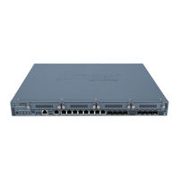
Juniper SRX345 Hardware Manual (106 pages)
Services Gateway
Brand:
Juniper
| Category:
Gateway
| Size: 2.33 MB
Table of Contents
Table of Contents
3
About the Documentation
11
Documentation and Release Notes
11
Using the Examples in this Manual
11
Merging a Full Example
12
Merging a Snippet
12
Documentation Conventions
13
About the Documentation
13
Table 1: Notice Icons
13
Table 2: Text and Syntax Conventions
14
Documentation Feedback
15
Requesting Technical Support
15
Self-Help Online Tools and Resources
16
Creating a Service Request with JTAC
16
Chapter 1 Overview
17
SRX345 Services Gateway Overview
17
SRX345 Services Gateway Description
17
Figure 1: SRX345 Services Gateway
17
SRX345 Services Gateway Field Replaceable Units Overview
18
Benefits of the SRX345 Services Gateway
18
SRX345 Chassis
19
SRX345 Services Gateway Chassis Overview
19
SRX345 Services Gateway Front Panel
19
Figure 2: SRX345 Services Gateway (Single AC Power Supply) Front Panel
19
Overview
19
Figure 3: SRX345 Services Gateway (Dual AC Power Supplies) Front Panel
20
Table 3: SRX345 Services Gateway Front Panel Components
20
Chassis Status Leds
21
Figure 4: SRX345 Services Gateway Front Panel Leds
21
Table 4: SRX345 Services Gateway Front Panel Leds
21
Management Port Leds
22
Network Port Leds
22
Table 5: Management Port Leds
22
Table 6: Network Port Leds
22
Figure 5: SRX345 Services Gateway Back Panel (Single AC Power Supply)
23
Figure 6: SRX345 Services Gateway Back Panel (Dual AC Power Supplies)
23
Figure 7: SRX345 Services Gateway Back Panel (DC Power Supply)
23
SRX345 Services Gateway Back Panel
23
Table 7: SRX345 Services Gateway Back Panel Components
23
SRX345 Services Gateway Interface Modules Overview
24
SRX345 Cooling System
24
Table 8: SRX345 Services Gateway (with Dual AC Power Supplies) Back Panel
24
SRX345 Power System
25
SRX345 Services Gateway Power Supply
25
SRX345 Services Gateway Power Specifications and Requirements
25
Figure 8: Airflow through the SRX345 Services Gateway Chassis
25
SRX345 Services Gateway Supported AC Power Cords
26
Table 9: Power System Electrical Specifications for the SRX345 Services
26
Table 10: Power System Electrical Specifications for the SRX345 Services Gateway (DC Model)
26
Table 11: AC Power Cord Specifications
26
Figure 9: AC Plug Types
27
Chapter 2 Site Planning, Preparation, and Specifications
29
SRX345 Site Preparation Checklist
29
Table 12: Site Preparation Checklist for SRX345 Services Gateway
29
SRX345 Site Guidelines and Requirements
31
General Site Installation Guidelines for the SRX345 Services Gateway
31
SRX345 Services Gateway Environmental Specifications
31
Table 13: Environmental Specifications for the SRX345 Services Gateway
31
SRX345 Services Gateway Electrical Wiring Guidelines
32
Table 14: Site Electrical Wiring Guidelines for the SRX345 Services Gateway
32
SRX345 Services Gateway Grounding Specifications
33
SRX345 Services Gateway Physical Specifications
33
Table 15: Grounding Cable Specifications for the Services Gateway
33
Table 16: Physical Specifications for the SRX345 Services Gateway
33
SRX345 Services Gateway Clearance Requirements for Airflow and Hardware Maintenance
34
Rack Requirements
34
Cabinet Requirements
35
SRX345 Transceiver Specifications and Pinouts
35
SRX345 Transceiver Support
36
Connector Pinouts for the SRX345 Services Gateway Ethernet
36
Port
36
Table 17: RJ-45 Connector Pinouts for the SRX345 Services Gateway Ethernet
36
Table 18: RJ-45 Connector Pinouts for the SRX345 Services Gateway Console
36
Port
37
Mini-USB Connector Pinouts for the SRX345 Services Gateway Console
37
Table 19: Mini-USB Type-B Connector Pinouts for the Services Gateway Console
37
Chapter 3 Initial Installation and Configuration
39
SRX345 Installation Overview
39
SRX345 Services Gateway Installation Overview
39
SRX345 Services Gateway Autoinstallation Overview
40
Unpacking and Mounting the SRX345
41
Unpacking the SRX345 Services Gateway
41
Verifying Parts Received with the SRX345 Services Gateway
42
Table 20: Parts List for a Fully Configured SRX345 Services Gateway
42
Table 21: Accessory Parts List for the SRX345 Services Gateway
42
Preparing the SRX345 Services Gateway for Rack-Mount Installation
43
Installing the SRX345 Services Gateway into a Rack
43
Figure 10: Installing the Rack Mount Brackets (Front Mount Position)
44
Figure 11: Installing the Rack Mount Brackets (Center Mount Position)
44
Connecting the SRX345 to Power
45
Required Tools and Parts for Grounding the SRX345 Services Gateway
45
Figure 12: Installing the Services Gateway in the Rack (Front Mount Shown, Center Mount Similar)
45
Connecting the SRX345 Services Gateway Grounding Cable
46
Figure 13: Connecting the Grounding Cable to the SRX345 Services Gateway
46
Connecting the SRX345 Services Gateway to an AC Power Supply
47
Connecting the SRX345 Services Gateway to a DC Power Supply
48
Figure 14: Connecting the SRX345 Services Gateway to an AC Power Supply
48
Powering on the SRX345 Services Gateway
49
Figure 15: Connecting the SRX345 Services Gateway to a DC Power Supply
49
Powering off the SRX345 Services Gateway
50
Connecting the SRX345 to External Devices
51
Connecting the Dial-Up Modem to the Console Port on the SRX345 Services Gateway
51
Connecting to the SRX345 Services Gateway CLI Using a Dial-Up
51
Modem
52
Configuring Junos os on the SRX345
53
SRX345 Services Gateway Software Configuration Overview
53
Understanding SRX345 Services Gateway Factory-Default Settings
53
Related Configuring Junos os on the SRX345
53
Configuring Zero-Touch Provisioning on SRX Series Devices
54
Table 22: Default Interface Configuration for the SRX345 Services Gateway
54
Accessing J-Web on the SRX345 Services Gateway
55
Figure 16: Connecting to the Management Port on the SRX345 Services
55
About the Setup Wizard
56
Configuring the SRX345 Services Gateway Using the J-Web Setup Wizard
56
Wizard
56
About the Default Setup Mode
57
About the Guided Setup Mode
58
Accessing the CLI on the SRX345 Services Gateway
59
Connecting to the SRX345 Services Gateway from the CLI Remotely
60
Configuring the SRX345 Services Gateway Using the CLI
60
Figure 17: Connecting to the Console Port on the SRX345 Services Gateway
60
Chapter 4 Maintaining Components
65
Maintaining the SRX345 Components
65
Required Tools and Parts for Maintaining the SRX345 Services Gateway Hardware Components
65
Routine Maintenance Procedures for the SRX345 Services Gateway
65
Maintaining the SRX345 Services Gateway Cooling System Components
66
Maintaining the SRX345 Services Gateway Power Supply
66
Replacing Mini-Physical Interface Modules in the SRX345 Services
67
Gateway
69
Chapter 5 Troubleshooting Hardware
69
Troubleshooting the SRX345
69
Troubleshooting Resources for the SRX345 Services Gateway Overview
69
Troubleshooting Chassis and Interface Alarm Messages on the SRX345 Services Gateway
69
Leds
69
Table 23: SRX345 Services Gateway Chassis Alarm Conditions and Corrective
70
Troubleshooting the Power System on the SRX345 Services Gateway
71
Table 24: SRX345 Services Gateway Power LED Status
71
Using the RESET CONFIG Button
72
Changing the RESET CONFIG Button Behavior
72
Chapter 6 Contactingcustomersupportandreturningthechassisor
75
Components
75
Returning the SRX345 Chassis or Components
75
Contacting Customer Support
75
Returning a SRX345 Services Gateway Component to Juniper Networks
76
Labels
76
Locating the SRX345 Services Gateway Chassis Serial Number and Agency Labels
76
Locating the SRX345 Services Gateway Mini-Physical Interface Module Serial Number Label
77
Listing the SRX345 Services Gateway Component Details with the CLI
77
Required Tools and Parts for Packing the SRX345 Services Gateway
77
Packing the SRX345 Services Gateway for Shipment
78
Packing SRX345 Services Gateway Components for Shipment
79
Chapter 7 Safety and Compliance Information
81
Definitions of Safety Warning Levels
81
General Safety Guidelines and Warnings
83
Restricted Access Warning
84
Qualified Personnel Warning
85
Prevention of Electrostatic Discharge Damage
86
Fire Safety Requirements
87
Fire Suppression
87
Fire Suppression Equipment
87
Figure 18: Placing a Component into an Antistatic Bag
87
Laser and LED Safety Guidelines and Warnings
88
General Laser Safety Guidelines
88
Class 1 Laser Product Warning
89
Class 1 LED Product Warning
89
Laser Beam Warning
89
Radiation from Open Port Apertures Warning
90
Maintenance and Operational Safety Guidelines and Warnings
91
Battery Handling Warning
91
Jewelry Removal Warning
92
Lightning Activity Warning
93
Operating Temperature Warning
94
Product Disposal Warning
95
Action to Take after an Electrical Accident
96
General Electrical Safety Guidelines and Warnings
96
AC Power Electrical Safety Guidelines
97
DC Power Electrical Safety Guidelines
98
DC Power Disconnection Warning
99
DC Power Grounding Requirements and Warning
100
DC Power Wiring Sequence Warning
101
DC Power Wiring Terminations Warning
102
SRX345 Services Gateway Agency Approvals
103
SRX345 Services Gateway Acoustic Noise Compliance Statements
105
SRX345 Services Gateway EMC Requirements
105
Canada
105
European Community
105
Israel
105
Japan
106
United States
106
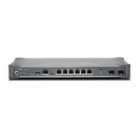
Juniper SRX345 Hardware Manual (119 pages)
Firewall
Brand:
Juniper
| Category:
Network Hardware
| Size: 2.72 MB
Table of Contents
Table of Contents
3
About this Guide
7
1 Overview
8
SRX345 Firewall Overview
9
SRX345 Firewall Description
9
SRX345 Firewall Field Replaceable Units Overview
10
Benefits of the SRX345 Firewall
10
SRX345 Chassis
11
SRX345 Firewall Chassis Overview
11
SRX345 Firewall Front Panel
12
SRX345 Firewall Back Panel
17
SRX345 Firewall Interface Modules Overview
19
SRX345 Cooling System
20
SRX345 Power System
21
SRX345 Firewall Power Supply
22
SRX345 Firewall Power Specifications and Requirements
23
SRX345 Firewall Supported AC Power Cords
24
2 Site Planning, Preparation, and Specifications
26
SRX345 Site Preparation Checklist
27
SRX345 Site Guidelines and Requirements
29
General Site Installation Guidelines for the SRX345 Firewall
29
SRX345 Firewall Environmental Specifications
30
SRX345 Firewall Electrical Wiring Guidelines
30
SRX345 Firewall Physical Specifications
32
SRX345 Firewall Clearance Requirements for Airflow and Hardware Maintenance
32
Rack Requirements
33
Cabinet Requirements
33
SRX345 Transceiver Specifications and Pinouts
34
SRX345 Transceiver Support
35
RJ-45 Connector Pinouts for the SRX345 Firewall Ethernet Port
35
RJ-45 Connector Pinouts for the SRX345 Firewall Console Port
36
Mini-USB Connector Pinouts for the SRX345 Firewall Console Port
37
3 Initial Installation and Configuration
38
SRX345 Installation Overview
39
SRX345 Firewall Installation Overview
39
SRX345 Firewall Autoinstallation Overview
39
Unpacking and Mounting the SRX345
40
Unpacking the SRX345 Firewall
41
Verifying Parts Received with the SRX345 Firewall
42
Preparing the SRX345 Firewall for Rack-Mount Installation
43
Installing the SRX345 Firewall into a Rack
44
Connecting the SRX345 to Power
45
Required Tools and Parts for Grounding the SRX345 Services Gateway
46
Connecting the SRX345 Firewall Grounding Cable
46
Connecting the SRX345 Firewall to an AC Power Supply
48
Connecting the SRX345 Firewall to a DC Power Supply
49
Powering on the SRX345 Firewall
51
Powering off the SRX345 Services Gateway
52
Connecting the SRX345 to External Devices
53
Connecting the Dial-Up Modem to the Console Port on the SRX345 Services Gateway | 46
53
Connecting to the SRX345 Firewall CLI Using a Dial-Up Modem
54
Configuring Junos os on the SRX345
55
SRX345 Firewall Factory-Default Settings
55
Initial Configuration Using the CLI
58
Connect to the Serial Console Port
58
Connect to the Mini-USB Console Port
59
Configure the SRX345 Using the CLI
60
Initial Configuration Using J-Web
61
Configure Using J-Web
61
Customize the Configuration for Junos os Release 19.2
63
Customize the Configuration for Junos os Release 15.1X49-D170
64
Configure the Device Using ZTP with Juniper Networks Network Service Controller
65
Installing the Optional SATA Solid-State Drive in SRX340 and SRX345 Services Gateways
66
4 Maintaining Components
71
Maintaining the SRX345 Components
72
Required Tools and Parts for Maintaining the SRX345 Firewall Hardware Components
72
Routine Maintenance Procedures for the SRX345 Services Gateway
72
Maintaining the SRX345 Firewall Cooling System Components
73
Maintaining the SRX345 Firewall Power Supply
73
Replacing Mini-Physical Interface Modules in the SRX345 Firewall
74
5 Troubleshooting Hardware
75
Troubleshooting the SRX345
76
Troubleshooting Resources for the SRX345 Firewall Overview
76
Troubleshooting Chassis and Interface Alarm Messages on the SRX345 Firewall | 69
76
Troubleshooting the Power System on the SRX345 Firewall
78
Using the RESET CONFIG Button
80
Changing the RESET CONFIG Button Behavior
80
6 Contacting Customer Support and Returning the Chassis or Components
82
Returning the SRX345 Chassis or Components
83
Contacting Customer Support
83
Returning a SRX345 Firewall Component to Juniper Networks
84
Locating the SRX345 Firewall Chassis Serial Number and Agency Labels
84
Locating the Mini-PIM Serial Number Label
85
Listing the SRX345 Firewall Component Details with the CLI
85
Required Tools and Parts for Packing the SRX Series Services Gateway
85
Packing the SRX Series Services Gateway for Shipment
86
Packing SRX Series Services Gateway Components for Shipment
86
Definitions of Safety Warning Levels
89
General Safety Guidelines and Warnings
90
Restricted Access Warning
92
Qualified Personnel Warning
93
Prevention of Electrostatic Discharge Damage
94
Fire Safety Requirements
95
Laser and LED Safety Guidelines and Warnings
97
Radiation from Open Port Apertures Warning
99
Maintenance and Operational Safety Guidelines and Warnings
100
Action to Take after an Electrical Accident
106
General Electrical Safety Guidelines and Warnings
106
AC Power Electrical Safety Guidelines
107
DC Power Electrical Safety Guidelines
108
SRX345 Firewall Agency Approvals
115
SRX345 Firewall Acoustic Noise Compliance Statements
117
SRX345 Firewall EMC Requirements
117
Canada
117
European Community
118
Israel
118
Japan
118
United States
119
Juniper SRX345 Manual (10 pages)
Brand:
Juniper
| Category:
Gateway
| Size: 1.8 MB
Table of Contents
Table of Contents
1
Step 1: Begin
1
Meet the SRX345
1
Install the SRX345
2
Install the SRX345 in a Rack
3
Power on
4
Step 2: up and Running
5
Step 3: Keep Going
9
Juniper SRX345 Quick Start Manual (12 pages)
Brand:
Juniper
| Category:
Gateway
| Size: 1.42 MB
Table of Contents
In this Section
2
Step 2: up and Running
5
Perform Initial Configuration
8
What's Next
11
General Information
12
Juniper SRX345 How To Set Up (10 pages)
Brand:
Juniper
| Category:
Gateway
| Size: 1.73 MB
Table of Contents
Front Panel
1
Package Contents
1
Factory Default Settings
2
Power off the Device
8
Reset the Configuration
9
Next Steps
9
Advertisement
Related Products
Juniper SRX3600
Juniper SRX3400
Juniper SRX320
Juniper SRX300 Series
Juniper SRX340
Juniper SRX380
Juniper SRX 1400 SERVICES GATEWAY -
Juniper SRX110 H2
Juniper SRX 5800
Juniper SRX1500
Juniper Categories
Network Router
Switch
Gateway
Software
Network Hardware
More Juniper Manuals
Login
Sign In
OR
Sign in with Facebook
Sign in with Google
Upload manual
Upload from disk
Upload from URL