Sign In
Upload
Manuals
Brands
Juniper Manuals
Gateway
SRX3400
Juniper SRX3400 Manuals
Manuals and User Guides for Juniper SRX3400. We have
7
Juniper SRX3400 manuals available for free PDF download: Hardware Manual, Manual, Instructions
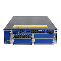
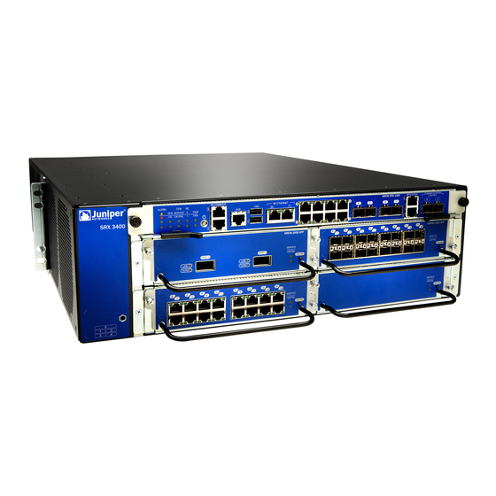
Juniper SRX3400 Hardware Manual (286 pages)
Services
Brand:
Juniper
| Category:
Gateway
| Size: 11.14 MB
Table of Contents
Table of Contents
3
About the Documentation
17
Documentation and Release Notes
17
Supported Platforms
17
Documentation Conventions
17
Table 1: Notice Icons
18
Table 2: Text and Syntax Conventions
18
Documentation Feedback
19
About the Documentation
19
Requesting Technical Support
20
Self-Help Online Tools and Resources
20
Opening a Case with JTAC
20
Overview
23
System Overview
23
Chassis Description
23
Line Card and Module Description
23
Hardware Component Overview
23
Chapter 1 System Overview
25
System Overview
25
SRX3400 Services Gateway Description
25
Figure 1: SRX3400 Services Gateway
25
Data Flow in the SRX3400 Services Gateway
26
Chapter 2 Hardware Component Overview
27
Available Components for the SRX3400 Services Gateway
27
Table 3: Available SRX3400 Services Gateway Hardware Components
27
Table 4: Supported Combinations of Spcs, Npcs, and Iocs
28
SRX3400 Services Gateway Cfms
29
SRX3400 Services Gateway Switch Fabric Board
29
Hardware Component Overview
29
Figure 2: Switch Fabric Board
29
Table 5: Power Button Behavior
30
Table 6: Switch Fabric Board LED Indicators
30
Table 7: Switch Fabric Board Front Panel Ports and Connectors
33
SRX3400 Services Gateway Npcs
35
SRX3400 Services Gateway Spcs
35
Figure 3: Typical NPC
35
SRX3400 Services Gateway Iocs
36
Figure 4: Typical Services Processing Card
36
SRX3400 Services Gateway NP-Iocs
37
Figure 5: Typical IOC
37
SRX3400 Services Gateway Routing Engine
38
Figure 6: Typical NP-IOC
38
SRX3400 Services Gateway SRX Clustering Module
39
Figure 8: SRX Clustering Module
39
Chapter 3 Chassis Description
41
Hardware Component Locations in the SRX3400 Services Gateway Chassis
42
Figure 7: Routing Engine
42
Figure 10: Rear View of the SRX3400 Services Gateway
42
Table 8: Allowed Slot Locations for the SRX3400 Services Gateway
42
Components
42
Figure 11: Front Slots on the SRX3400 Services Gateway
43
Figure 12: Rear Slots on the SRX3400 Services Gateway
43
Chassis Description
43
SRX3400 Services Gateway Midplane
44
Figure 13: Midplane
44
Chassis Description
41
SRX3400 Services Gateway Chassis
41
Figure 9: Front View of the SRX3400 Services Gateway
41
Chapter 4 Line Card and Module Description
45
SRX1400, SRX3400, and SRX3600 Services Gateway Module Overview
45
Modules Supported on SRX1400, SRX3400, and SRX3600 Services
45
Gateways
46
Eligible Slots for SRX1400, SRX3400, and SRX3600 Services Gateway
46
Modules
46
Table 9: Supported Modules for SRX1400, SRX3400, and SRX3600 Services
46
Gateways
47
Table 10: Supported Slots for SRX1400, SRX3400, and SRX3600 Services Gateway Modules
48
Services Processing Card SRX3K-SPC-1-10-40
49
Figure 14: SRX3K-SPC-1-10-40 SPC
49
Figure 15: SPC Serial Number Label
50
Network Processing Card SRX3K-NPC
51
Figure 16: Network Processing Card SRX3K-NPC
51
I/O Card SRX3K-16GE-TX
52
Figure 17: NPC Serial Number Label
52
Figure 18: 16-Port Copper 10/100/1000 IOC
53
I/O Card SRX3K-16GE-SFP
54
Figure 19: IOC Serial Number Label
54
Figure 20: 16-Port SFP Gigabit Ethernet IOC
54
I/O Card SRX3K-2XGE-XFP
56
Figure 22: 2-Port XFP 10-Gigabit Ethernet IOC
56
Network Processing I/O Card SRX1K3K-NP-2XGE-SFPP
58
Figure 24: NP-IOC SRX1K3K-NP-2XGE-SFPP
58
Routing Engines SRX3K-RE-12-10 and SRX1K-RE-12-10
60
Figure 26: Routing Engine
61
Figure 27: Routing Engine Serial Number Label
62
SRX Clustering Module SRX3K-CRM
63
Figure 28: SRX Clustering Module SRX3K-CRMSRX3K-CRM
63
Figure 29: SCM Serial Number Label
64
Chapter 5 Cooling System Description
65
SRX3400 Services Gateway Fan Tray
65
Figure 30: Fan Tray
65
Figure 31: Airflow through the Chassis
66
Table 11: Critical Component Temperatures and Fan Speed Transitions
66
SRX3400 and SRX5600 Services Gateways Air Deflector Kits
67
Table 12: Services Gateway and Air Deflector Dimensions
67
Figure 32: SRX3400 Services Gateway Air Deflector Kit
68
Figure 33: SRX5600 Services Gateway Air Deflector Kit (Services Gateway Chassis Contents Omitted for Clarity)
68
Chapter 6 Power System Description
69
SRX3400 Services Gateway AC Power Supply Overview
69
Figure 34: AC Power Supply
69
SRX3400 Services Gateway DC Power Supply Overview
70
Figure 35: DC Power Supply
70
Site Planning and Specifications
71
Chapter 7 Planning and Preparing the Site
73
SRX3400 Services Gateway Physical Specifications
74
Table 13: Site Electrical Wiring Guidelines
74
SRX3400 Services Gateway Environmental Specifications
75
Table 14: Physical Specifications
75
Site Preparation Checklist for the SRX3400 Services Gateway
76
Table 15: SRX3400 Services Gateway Environmental Specifications
76
Table 16: Site Preparation Checklist
76
Planning and Preparing the Site
73
General Site Guidelines
73
Site Electrical Wiring Guidelines
73
Chapter 8 Rack Requirements
79
SRX3400 Services Gateway Spacing of Mounting Bracket Holes
80
Figure 36: Typical Open-Frame Rack
80
Connecting the SRX3400 Services Gateway to the Building Structure
81
Clearance Requirements for Airflow and Hardware Maintenance of the SRX3400 Services Gateway
81
Figure 37: Clearance Requirements
82
Rack Requirements
79
SRX3400 Services Gateway Rack Size and Strength Requirements
79
Cabinet Requirements
83
SRX3400 Services Gateway Cabinet Size and Clearance Requirements
83
Chapter 9 Cabinet Requirements
83
SRX3400 Services Gateway Cabinet Airflow Requirements
84
Chapter 10 Grounding Specifications
85
Grounding Specifications
85
SRX3400 Services Gateway Grounding-Cable Lug Specification
85
SRX3400 Services Gateway Grounding Cable Specification
85
Figure 38: Grounding Cable Lug
85
Table 17: Grounding Cable Specifications
86
Chapter 11 AC Power Requirements and Specifications
87
SRX3400 Services Gateway AC Power Supply Electrical Specifications
87
Table 18: AC Power Supply Electrical Specifications
87
SRX3400 Services Gateway AC Power System Electrical Specifications
88
Table 19: AC Power Supply LED
88
Table 20: AC Power System Specifications
88
SRX3400 Services Gateway AC Power Cord Specifications
89
Table 21: AC Power Cord Specifications
89
Figure 39: AC Plug Types
90
Power Requirements for AC-Powered SRX3400 Services Gateways
91
Table 22: Base System AC Power Requirements
91
Table 23: Component AC Power Requirements
91
Chapter 12 DC Power Requirements and Specifications
93
SRX3400 Services Gateway DC Power Supply Electrical Specifications
93
Table 24: DC Power Supply Electrical Specifications
93
SRX3400 Services Gateway DC Power System Electrical Specifications
94
Table 25: DC Power Supply LED
94
Table 26: DC Power System Electrical Specifications
94
SRX3400 Services Gateway DC Power Cable Specifications
95
Figure 40: Typical DC Source Cabling to the SRX3400 Services Gateway
95
Power Requirements for DC-Powered SRX3400 Services Gateways
96
Table 27: DC Power Cable Specifications
96
Table 28: DC-Powered Base System Requirements
96
Table 29: Component DC Power Requirements
97
Chapter 13 Cable Specifications and Pinouts
99
Console Port Cable and Wire Specifications for the SRX3400 Services
99
Gateway
99
Table 30: Cable and Wire Specifications for Routing Engine Management and Alarm Interfaces
99
Distance Limitations for Signaling for the SRX3400 Services Gateway
100
Radio Frequency Interference for the SRX3400 Services Gateway
100
Electromagnetic Compatibility for the SRX3400 Services Gateway
100
Signal Loss in Multimode and Single-Mode Fiber-Optic Cable for the SRX3400 Services Gateway
101
Gateway
101
Table 31: Estimated Values for Factors that Cause Link Loss
103
Gateway
104
Initial Installation and Configuration
105
Chapter 14 Installation Overview
107
Installation Overview
107
Installation Overview for the SRX3400 Services Gateway
107
Chapter 15 Unpacking the Services Gateway
109
Required Tools and Parts for Unpacking the SRX3400 Services Gateway
109
Unpacking the SRX3400 Services Gateway
109
Figure 41: Unpacking the SRX3400 Services Gateway
110
Verifying Parts Received with the SRX3400 Services Gateway
111
Table 32: Parts List for a Fully Configured SRX3400 Services Gateway
111
Table 33: Accessory Box Parts List
112
Chapter 16 Installing the Mounting Hardware
113
Installing the Mounting Hardware for the SRX3400 Services Gateway
113
Figure 42: Attaching Mounting Hardware for Two-Post Rack
113
Figure 43: Attaching Mounting Hardware for Cabinet or Four-Post Rack
114
Figure 44: Attaching Four-Post and Cabinet Support Shelf
114
Chapter 17 Installing the SRX3400 Services Gateway Using a Mechanical Lift
115
Required Tools for Installing the SRX3400 Services Gateway
115
Preparing the SRX3400 Services Gateway for Rack-Mount or Cabinet
115
Installation
115
Mechanical Lift
116
Figure 45: Load the Services Gateway Onto the Lift
116
Figure 46: Installing the Services Gateway in a Two-Post Rack
117
Figure 47: Installing the Services Gateway in a Four-Post Rack
117
Chapter 18 Installing the SRX3400 Services Gateway Without a Mechanical Lift
119
Mechanical Lift
119
Removing Components from the Chassis for Manual Lifting of the SRX3400 Services Gateway
119
Figure 48: Components to Remove from the Front of the Services Gateway
120
Figure 49: Components to Remove from the Rear of the Services Gateway
120
Lifting the SRX3400 Services Gateway Chassis into the Rack
121
Reinstalling Components in the SRX3400 Services Gateway Chassis
122
Figure 50: Lifting the Chassis into the Rack
122
Chapter 19 Installing Additional Hardware Components
125
Installing CFM Cards in the SRX3400 Services Gateway
125
Figure 51: Installing a CFM (SPC Shown, Other Cfms Similar)
127
Installing Spcs in an Operating SRX3400 Services Gateway Chassis Cluster
128
Installing an SCM in the SRX3400 Services Gateway
132
Figure 52: Installing the SCM in the SRX3400 Services Gateway
132
Installing an AC Power Supply in the SRX3400 Services Gateway
133
Figure 53: Identifying Power Supply Types
133
Figure 54: Installing an AC Power Supply
134
Installing a DC Power Supply in the SRX3400 Services Gateway
135
Figure 55: Identifying Power Supply Types
135
Figure 56: Installing a DC Power Supply
136
Chapter 20 Grounding the SRX3400 Services Gateway
137
Services Gateway
137
SRX3400 Services Gateway Chassis Grounding Point
137
Figure 57: Grounding Point on Rear of SRX3400 Services Gateway
138
Grounding the SRX3400 Services Gateway
139
Figure 58: Connecting the Grounding Cable
140
Chapter 21 Connecting the SRX3400 Services Gateway to External Devices
141
Required Tools and Parts for Connecting the SRX3400 Services Gateway
141
Auxiliary Device
141
Management
141
Figure 59: Connecting to the Console Port
142
Figure 60: Console and Auxiliary Cable Connector
142
Figure 61: SFB Ethernet Cable Connector
143
Chapter 22 Providing Power to the SRX3400 Services Gateway
145
Connecting the SRX3400 Services Gateway to an AC Power Source
145
Figure 62: Connecting to AC Power
146
Connecting the SRX3400 Services Gateway to a DC Power Source
147
Powering on the SRX3400 Services Gateway
149
Figure 63: Connecting to DC Power
149
Powering off the SRX3400 Services Gateway
150
Chapter 23 Performing the Initial Configuration
153
SRX3400 Services Gateway Software Configuration Overview
153
Gateway
154
Performing Initial Software Configuration Using J-Web
158
Configuring Root Authentication and the Management Interface from the CLI
158
Configuring Interfaces, Zones, and Policies with J-Web
159
Configuring the Hostname
160
Configuring Interfaces
160
Configuring Zones and Assigning Interfaces
161
Configuring Security Policies
161
Maintaining and Troubleshooting Components
163
Chapter 24 Maintaining Components
165
Maintaining the Air Filter on the SRX3400 Services Gateway
166
Components
166
Maintaining the Fan Tray on the SRX3400 Services Gateway
167
Maintaining the Routing Engine on the SRX3400 Services Gateway
168
Maintaining the Power Supplies on the SRX3400 Services Gateway
169
Maintaining Components
165
Required Tools and Parts for Maintaining the SRX3400 Services Gateway Hardware Components
165
Routine Maintenance Procedures for the SRX3400 Services Gateway
165
Chapter 25 Troubleshooting Components
171
Troubleshooting with Leds on the SRX3400 Services Gateway
172
Troubleshooting with Chassis and Interface Alarm Messages on the SRX3400 Services Gateway
172
Gateways
172
Table 34: Chassis Component Alarm Conditions on SRX3400 and SRX3600
173
Backup Routing Engine Alarms
178
Table 35: Backup Routing Engine Alarms
178
Troubleshooting the Cooling System on the SRX3400 Services Gateway
179
Troubleshooting Iocs and NP-Iocs on the SRX3400 Services Gateway
180
Troubleshooting Npcs on the SRX3400 Services Gateway
182
Troubleshooting Spcs on the SRX3400 Services Gateway
183
Troubleshooting the Power System on the SRX3400 Services Gateway
184
Troubleshooting Components
171
Troubleshooting with the CLI on the SRX3400 Services Gateway
171
Replacing Components
187
Chapter 26 Overview of Replacing Components
189
Field-Replaceable Units on the SRX3400 Services Gateway
189
Table 36: Field-Replaceable Units
189
Required Tools and Parts for Replacing Hardware Components on the SRX3400 Services Gateway
190
Table 37: Tools and Parts Required
190
Chapter 27 Replacing Cables and Connectors
193
Replacing Cables and Connectors
193
Replacing SFP, SFP+, and XFP Transceivers on the SRX3400 Services
193
Gateway
193
Table 38: Extended Temperature SFP, SFP+, and XFP Transceivers
193
Figure 64: Removing SFP, SFP+, or XFP Transceivers
195
Chapter 28 Replacing Host Subsystem Components
197
Figure 65: Removing the SFB
198
Figure 66: Inserting the SFB
198
Replacing a Routing Engine on the SRX3400 Services Gateway
199
Figure 67: Removing a Routing Engine
200
Figure 68: Installing a Routing Engine
201
Figure 69: Location of CR2032 Battery in a Routing Engine
203
Removing the Battery from the Routing Engine of an SRX3400 Services Gateway for Recycling
203
Replacing a CFM Card on the SRX3400 Services Gateway
204
Figure 70: Removing a CFM (IOC Shown, Other Cfms Similar)
205
Figure 71: Inserting a CFM (IOC Shown, Other Cfms Similar)
206
Replacing an SCM on the SRX3400 Services Gateway
207
Figure 72: Removing an SCM
208
Figure 73: Installing an SCM
209
Replacing Host Subsystem Components
197
Replacing the SFB on the SRX3400 Services Gateway
197
Chapter 29 Replacing Cooling System Components
211
Replacing the Fan Tray on the SRX3400 Services Gateway
211
Figure 74: Removing the Fan Tray Door
212
Figure 75: Removing the Fan Tray
213
Replacing the Air Filter on the SRX3400 Services Gateway
214
Figure 76: Inserting the Fan Tray
214
Figure 77: Removing the Fan Tray Door
215
Figure 78: Removing the Air Filter
215
Figure 79: Installing the Air Filter
216
Chapter 30 Replacing Power Supply Components
217
Replacing an AC Power Supply on the SRX3400 Services Gateway
218
Figure 80: Identifying Power Supply Types
218
Figure 81: Removing an AC Power Supply
219
Figure 82: Inserting an AC Power Supply
219
Replacing AC Power Supply Cables on the SRX3400 Services Gateway
220
Figure 83: Inserting an AC Power Cord
221
Replacing a DC Power Supply on the SRX3400 Services Gateway
222
Figure 84: Identifying Power Supply Types
222
Figure 85: Removing a DC Power Supply
223
Figure 86: Inserting a DC Power Supply
224
Replacing DC Power Supply Cables on the SRX3400 Services Gateway
225
Figure 87: Connecting DC Power Cables
226
Chapter 31 Contactingcustomersupport
227
Contacting Customer Support
227
Return Procedure for the SRX3400 Services Gateway
228
Cli
229
Locating the SRX3400 Services Gateway Chassis Serial Number Label
230
Label
230
Figure 88: SRX3400 Services Gateway Chassis Serial Number Label
230
Figure 89: Routing Engine Serial Number Label
230
Locating the SRX3400 Services Gateway SFB Serial Number Label
231
Label
231
Figure 90: SFB Serial Number Label
231
Figure 91: AC Power Supply Serial Number Label
231
Information You Might Need to Supply to JTAC
232
Required Tools and Parts for Packing the SRX3400 Services Gateway
232
Packing the SRX3400 Services Gateway for Shipment
232
Packing SRX3400 Services Gateway Components for Shipment
233
Part 6 Safety Guidelines
235
Chapter 32 General Safety Information
237
General Safety Guidelines and Warnings
237
Definitions of Safety Warning Levels
238
Restricted Access Area Warning
240
Fire Safety Requirements
241
Qualified Personnel Warning
242
Warning Statement for Norway and Sweden
243
Advertisement
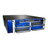
Juniper SRX3400 Hardware Manual (264 pages)
Services Gateway
Brand:
Juniper
| Category:
Gateway
| Size: 11.18 MB
Table of Contents
Table of Contents
3
About the Documentation
15
Documentation and Release Notes
15
Supported Platforms
15
Documentation Conventions
15
Table 1: Notice Icons
16
Table 2: Text and Syntax Conventions
16
Documentation Feedback
17
Requesting Technical Support
17
About the Documentation
17
Opening a Case with JTAC
18
Self-Help Online Tools and Resources
18
Introduction
19
Modules Supported on SRX1400, SRX3400, and SRX3600 Services
19
Hardware Specifications
19
Overview
19
Chapter 1 Introduction
21
Figure 1: SRX3400 Services Gateway
21
Introduction
21
SRX3400 Services Gateway Description
21
Employing the SRX3400 Services Gateway for Your Enterprise Gateway
22
SRX3400 Services Gateway Description
22
SRX3400 Services Gateway Performance and Features
22
Table 3: Summary of SRX3400 Services Gateway Features
22
Employing the SRX3400 Services Gateway in the Service Provider Network
23
Employing the SRX3400 Services Gateway in Your Enterprise Data Center
23
Introduction
23
Chapter 2 Hardware Specifications
25
SRX3400 Services Gateway Physical Specifications
25
Table 4: Physical Specifications
25
Console Port
25
SRX3400 Services Gateway Environmental Specifications
26
Table 5: SRX3400 Services Gateway Environmental Specifications
26
SRX3400 Services Gateway Grounding-Cable Lug Specification
27
SRX3400 Services Gateway Grounding Cable Specification
27
Gateway
27
Hardware Specifications
25
Figure 2: Grounding Cable Lug
27
Hardware Specifications
27
Table 6: Cable and Wire Specifications for Routing Engine Management and Alarm Interfaces
28
Chapter 3 Power Supply Specifications
29
SRX3400 Services Gateway AC Power Supply Electrical Specifications
29
Table 7: AC Power Supply Electrical Specifications
29
SRX3400 Services Gateway AC Power System Electrical Specifications
30
Table 8: AC Power Supply LED
30
Table 9: AC Power System Specifications
30
SRX3400 Services Gateway AC Power Cord Specifications
31
Power Supply Specifications
31
Table 10: AC Power Cord Specifications
31
Figure 3: AC Plug Types
32
SRX3400 Services Gateway DC Power Supply Electrical Specifications
33
Table 11: DC Power Supply Electrical Specifications
33
Table 12: DC Power Supply LED
33
SRX3400 Services Gateway DC Power Cable Specifications
34
SRX3400 Services Gateway DC Power System Electrical Specifications
34
Table 13: DC Power System Electrical Specifications
34
Figure 4: Typical DC Source Cabling to the SRX3400 Services Gateway
35
Table 14: DC Power Cable Specifications
36
Chapter 4 Hardware Components
37
Available Components for the SRX3400 Services Gateway
37
Table 15: Available SRX3400 Services Gateway Hardware Components
37
Hardware Component Locations in the SRX3400 Services Gateway Chassis
39
Hardware Components
37
Hardware Components
39
Table 16: Supported Combinations of Spcs, Npcs, and Iocs
39
Components
40
Figure 5: Front Slots on the SRX3400 Services Gateway
40
Figure 6: Rear Slots on the SRX3400 Services Gateway
40
Table 17: Allowed Slot Locations for the SRX3400 Services Gateway
40
Figure 7: Front View of the SRX3400 Services Gateway
41
SRX3400 Services Gateway Chassis
41
Figure 8: Rear View of the SRX3400 Services Gateway
42
SRX3400 Services Gateway Cfms
42
Data Flow in the SRX3400 Services Gateway
43
Figure 9: Midplane
43
SRX3400 Services Gateway Midplane
43
Figure 10: Switch Fabric Board
44
SRX3400 Services Gateway Switch Fabric Board
44
Table 18: Power Button Behavior
44
Table 19: Switch Fabric Board LED Indicators
45
Table 20: Switch Fabric Board Front Panel Ports and Connectors
48
Figure 11: Typical NPC
50
SRX3400 Services Gateway Npcs
50
SRX3400 Services Gateway Spcs
50
Figure 12: Typical Services Processing Card
51
SRX3400 Services Gateway Iocs
51
Figure 13: Typical IOC
52
SRX3400 Services Gateway NP-Iocs
52
Figure 14: Typical NP-IOC
53
SRX3400 Services Gateway Routing Engine
53
Figure 15: Routing Engine
54
Figure 16: SRX Clustering Module
54
SRX3400 Services Gateway SRX Clustering Module
54
Figure 17: AC Power Supply
55
SRX3400 Services Gateway AC Power Supply Overview
55
SRX3400 Services Gateway DC Power Supply Overview
55
Figure 18: DC Power Supply
56
SRX3400 Services Gateway Fan Tray
56
Figure 19: Fan Tray
57
Figure 20: Airflow through the Chassis
57
Table 21: Critical Component Temperatures and Fan Speed Transitions
58
Chapter 5 Modules Supported on SRX1400, SRX3400, and SRX3600 Services
59
Gateways
59
SRX1400, SRX3400, and SRX3600 Services Gateway Module Overview
59
Eligible Slots for SRX1400, SRX3400, and SRX3600 Services Gateway
59
Modules
59
Modules Supported on SRX1400, SRX3400, and SRX3600 Services
60
Gateways
61
Table 22: Supported Modules for SRX1400, SRX3400, and SRX3600 Services
61
Table 23: Supported Slots for SRX1400, SRX3400, and SRX3600 Services Gateway Modules
62
Hot-Swappable and Cold-Swap-Only Modules on the SRX1400, SRX3400, and SRX3600 Services Gateways
63
Table 24: Hot-Swappable and Cold-Swap-Only Modules
63
Services Processing Card SRX3K-SPC-1-10-40
64
Figure 21: SRX3K-SPC-1-10-40 SPC
64
Network Processing Card SRX3K-NPC
65
Figure 22: SPC Serial Number Label
65
Figure 23: Network Processing Card SRX3K-NPC
66
Figure 24: NPC Serial Number Label
66
I/O Card SRX3K-16GE-TX
67
Figure 25: 16-Port Copper 10/100/1000 IOC
67
I/O Card SRX3K-16GE-SFP
68
Figure 26: IOC Serial Number Label
68
Figure 27: 16-Port SFP Gigabit Ethernet IOC
69
I/O Card SRX3K-2XGE-XFP
70
Figure 28: IOC Serial Number Label
70
Figure 29: 2-Port XFP 10-Gigabit Ethernet IOC
70
Network Processing I/O Card SRX1K3K-NP-2XGE-SFPP
72
Figure 31: NP-IOC SRX1K3K-NP-2XGE-SFPP
72
Routing Engines SRX3K-RE-12-10 and SRX1K-RE-12-10
73
Figure 32: IOC Serial Number Label
73
Figure 33: Routing Engine
74
Figure 34: Routing Engine Serial Number Label
75
SRX Clustering Module SRX3K-CRM
76
Figure 35: SRX Clustering Module SRX3K-CRMSRX3K-CRM
76
Figure 36: SCM Serial Number Label
77
Part 2 Planning
79
Preparing the Site for Installation
81
Planning
79
Chapter 6 Preparing the Site for Installation
81
Site Preparation Checklist for the SRX3400 Services Gateway
81
Table 25: Site Preparation Checklist
81
Chapter 7 Cabinet and Rack Requirements
83
SRX3400 Services Gateway Cabinet Size and Clearance Requirements
83
SRX3400 Services Gateway Cabinet Airflow Requirements
84
SRX3400 Services Gateway Rack Size and Strength Requirements
84
Figure 37: Typical Open-Frame Rack
85
SRX3400 Services Gateway Spacing of Mounting Bracket Holes
86
Connecting the SRX3400 Services Gateway to the Building Structure
86
Clearance Requirements for Airflow and Hardware Maintenance of the SRX3400 Services Gateway
86
Figure 38: Clearance Requirements
87
Chapter 8 Power Requirements
89
Power Requirements for AC-Powered SRX3400 Services Gateways
89
Table 26: Base System AC Power Requirements
89
Table 27: Component AC Power Requirements
90
Power Requirements for DC-Powered SRX3400 Services Gateways
91
Table 28: DC-Powered Base System Requirements
91
Table 29: Component DC Power Requirements
91
Power Requirements
89
Chapter 9 Cable and Electrical Wiring Guidelines
93
Distance Limitations for Signaling for the SRX3400 Services Gateway
93
Radio Frequency Interference for the SRX3400 Services Gateway
93
Electromagnetic Compatibility for the SRX3400 Services Gateway
94
Signal Loss in Multimode and Single-Mode Fiber-Optic Cable for the SRX3400 Services Gateway
94
Gateway
94
Gateway
95
Calculating the Power Margin for Fiber-Optic Cable for the SRX3400 Services
95
Gateway
96
Table 30: Estimated Values for Factors that Cause Link Loss
96
Part 3 Safety
99
Chapter 10 Safety and Regulatory Warnings
101
SRX3400 Services Gateway Safety Requirements, Warnings, and Guidelines
101
SRX3400 Services Gateway Definition of Safety Warning Levels
101
SRX3400 Services Gateway General Safety Guidelines and Warnings
103
Preventing Electrostatic Discharge Damage to the SRX3400 Services
103
Gateway
104
Figure 39: ESD Point on Front of SRX3400 Services Gateway
104
SRX3400 Services Gateway Fire Safety Requirements and Fire Suppression
104
Equipment
105
Figure 40: ESD Point on Rear of SRX3400 Services Gateway
105
Figure 41: Placing a Component into an Electrostatic Bag
105
Equipment
106
Chapter 11 Installation Safety Guidelines and Warnings
107
Chassis Lifting Guidelines
107
Installation Instructions Warning
108
Rack-Mounting Requirements and Warnings
108
Ramp Warning
112
Chapter 12 Maintenance and Operation Warnings
115
Qualified Personnel Warning
115
Restricted Access Area Warning
116
Battery Handling Warning
117
Jewelry Removal Warning
119
Lightning Activity Warning
120
Operating Temperature Warning
121
Product Disposal Warning
122
Chapter 13 Agency Approval and Compliance Statements
125
SRX3400 Services Gateway Agency Approvals
125
SRX3400 Services Gateway Compliance Statements for EMC Requirements
126
Canada
126
European Community
126
Japan
127
United States
127
SRX3400 Services Gateway NEBS and ETSI Compliance
127
SRX3400 Services Gateway NEBS and ETSI Standards
127
SRX3400 Services Gateway NEBS and ETSI Configuration
127
Requirements
128
Figure 42: Power Supply Model and Revision Label (AC Shown, DC Similar)
128
Table 31: Extended Temperature SFP, SFP+, and XFP Transceivers
129
Chapter 14 Laser and LED Safety Guidelines and Warnings
131
General Laser Safety Guidelines
131
Class 1 Laser Product Warning
132
Class 1 LED Product Warning
132
Laser Beam Warning
133
Radiation from Open Port Apertures Warning
134
Chapter 15 Electrical Safety Guidelines and Warnings
135
General Electrical Safety Guidelines and Warnings
135
In Case of Electrical Accident
135
DC Power Electrical Safety Guidelines and Warnings
140
Part 4 Installation
147
Chapter 16 Unpacking the Services Gateway
149
Unpacking the SRX3400 Services Gateway
149
Figure 43: Unpacking the SRX3400 Services Gateway
150
Table 32: Parts List for a Fully Configured SRX3400 Services Gateway
151
Verifying Parts Received with the SRX3400 Services Gateway
151
Table 33: Accessory Box Parts List
152
Chapter 17 Installing the Mounting Hardware
153
Installing the Mounting Hardware for the SRX3400 Services Gateway
153
Figure 45: Attaching Mounting Hardware for Cabinet or Four-Post Rack
154
Figure 46: Attaching Four-Post and Cabinet Support Shelf
154
Chapter 18 Installing the Services Gateway Using a Mechanical Lift
155
Installing the SRX3400 Services Gateway in a Rack or Cabinet Using a Mechanical Lift
156
Required Tools for Installing the SRX3400 Services Gateway
156
Installation
156
Figure 47: Load the Services Gateway Onto the Lift
157
Figure 48: Installing the Services Gateway in a Two-Post Rack
158
Figure 49: Installing the Services Gateway in a Four-Post Rack
158
Chapter 19 Installing the Services Gateway Without a Mechanical Lift
159
Mechanical Lift
159
Services Gateway
159
Figure 50: Components to Remove from the Front of the Services Gateway
160
Figure 51: Components to Remove from the Rear of the Services Gateway
160
Lifting the SRX3400 Services Gateway Chassis into the Rack
161
Figure 52: Lifting the Chassis into the Rack
162
Reinstalling Components in the SRX3400 Services Gateway Chassis
162
Chapter 20 Installing Additional Hardware Components
163
Installing CFM Cards in the SRX3400 Services Gateway
163
Figure 53: Installing a CFM (SPC Shown, Other Cfms Similar)
165
Installing Spcs in an Operating SRX3400 Services Gateway Chassis Cluster
166
Installing an SCM in the SRX3400 Services Gateway
169
Figure 54: Installing the SCM in the SRX3400 Services Gateway
170
Installing an AC Power Supply in the SRX3400 Services Gateway
170
Figure 55: Identifying Power Supply Types
171
Figure 56: Installing an AC Power Supply
172
Figure 57: Identifying Power Supply Types
173
Installing a DC Power Supply in the SRX3400 Services Gateway
173
Figure 58: Installing a DC Power Supply
174
Chapter 21 Grounding, Powering On, and Powering off the Services Gateway
175
Chapter 22 Services Gateway
175
Figure 59: Connecting the Grounding Cable
176
Grounding the SRX3400 Services Gateway
176
Figure 60: Grounding Point on Rear of SRX3400 Services Gateway
177
Power Requirements for DC-Powered SRX3400 Services Gateways
177
SRX3400 Services Gateway Chassis Grounding Point
177
Table 34: DC-Powered Base System Requirements
178
Table 35: Component DC Power Requirements
178
Powering off the SRX3400 Services Gateway
179
Powering on the SRX3400 Services Gateway
179
Part 5 Configuration
181
Connecting the Services Gateway to the Network
183
Required Tools and Parts for Connecting the SRX3400 Services Gateway
183
Management
183
Connecting the SRX3400 Services Gateway to a Network for Out-Of-Band
183
Auxiliary Device
184
Figure 61: SFB Ethernet Cable Connector
184
Connecting the SRX3400 Services Gateway to an AC Power Source
185
Figure 62: Connecting to the Console Port
185
Figure 63: Console and Auxiliary Cable Connector
185
Figure 64: Connecting to AC Power
186
Connecting the SRX3400 Services Gateway to a DC Power Source
187
Figure 65: Connecting to DC Power
188
Chapter 23 Configuring Basic Settings
191
SRX3400 Services Gateway Software Configuration Overview
191
Performing Initial Software Configuration on the SRX3400 Services
192
Gateway
192
Part 6 Maintenance
197
Chapter 24 Maintaining Hardware Components
199
Required Tools and Parts for Maintaining the SRX3400 Services Gateway Hardware Components
199
Routine Maintenance Procedures for the SRX3400 Services Gateway
199
Maintaining the Air Filter on the SRX3400 Services Gateway
200
Maintaining the Fan Tray on the SRX3400 Services Gateway
200
Maintaining the Routing Engine on the SRX3400 Services Gateway
201
Maintaining the Power Supplies on the SRX3400 Services Gateway
203
Chapter 25 Replacing Hardware Components
205
Field-Replaceable Units on the SRX3400 Services Gateway
205
Required Tools and Parts for Replacing Hardware Components on the SRX3400 Services Gateway
206
Table 36: Field-Replaceable Units
206
Table 37: Tools and Parts Required
206
Replacing the Fan Tray on the SRX3400 Services Gateway
208
Figure 66: Removing the Fan Tray Door
208
Figure 67: Removing the Fan Tray
209
Figure 68: Inserting the Fan Tray
209
Replacing the Air Filter on the SRX3400 Services Gateway
210
Figure 69: Removing the Fan Tray Door
211
Figure 70: Removing the Air Filter
211
Figure 71: Installing the Air Filter
211
Replacing the SFB on the SRX3400 Services Gateway
212
Figure 72: Removing the SFB
212
Figure 73: Inserting the SFB
213
Replacing a Routing Engine on the SRX3400 Services Gateway
214
Figure 74: Removing a Routing Engine
214
Figure 75: Installing a Routing Engine
215
Replacing a CFM Card on the SRX3400 Services Gateway
216
Figure 76: Removing a CFM (IOC Shown, Other Cfms Similar)
217
Figure 77: Inserting a CFM (IOC Shown, Other Cfms Similar)
218
Replacing an SCM on the SRX3400 Services Gateway
219
Figure 78: Removing an SCM
220
Figure 79: Installing an SCM
220
Replacing SFP, SFP+, and XFP Transceivers on the SRX3400 Services
221
Gateway
221
Table 38: Extended Temperature SFP, SFP+, and XFP Transceivers
221
Figure 80: Removing SFP, SFP+, or XFP Transceivers
223
Juniper SRX3400 Hardware Manual (232 pages)
Services Gateway
Brand:
Juniper
| Category:
Gateway
| Size: 10.85 MB
Table of Contents
Table of Contents
3
Hardware Guide
1
Srx3400 Services Gateway
1
About this Guide
9
Audience
9
Documentation Conventions
9
Objectives
9
Obtaining Documentation
11
SRX Series Documentation and Release Notes
11
Documentation Feedback
12
Requesting Technical Support
12
SRX3400 Services Gateway Overview
15
Chapter 1 Introduction to the SRX3400 Services Gateway
17
Introduction to the SRX3400 Services Gateway
17
SRX3400 Services Gateway Description
17
SRX3400 Services Gateway Performance and Features
18
SRX3400 Services Gateway Physical Specifications
18
Components
21
Chapter 2 SRX3400 Services Gateway Hardware Components
21
SRX3400 Services Gateway Chassis
21
SRX3400 Services Gateway Component Basics
23
Available Components for the SRX3400 Services Gateway
23
SRX3400 Services Gateway Cfms
23
SRX3400 Services Gateway Midplane
24
SRX3400 Services Gateway Npcs
24
SRX3400 Services Gateway Spcs
24
SRX3400 Services Gateway Iocs
24
Chassis
25
Hardware Component Locations in the SRX3400 Services Gateway
25
Data Flow in the Srx3400 Services Gateway/Srx3400 Services Gateway Midplane
27
Data Flow in the SRX3400 Services Gateway
27
SRX3400 Services Gateway Midplane
27
SRX3400 Services Gateway Switch Fabric Board
28
Related SRX3400 Services Gateway Chassis
33
Available Components for the SRX3400 Services Gateway
33
Related SRX3400 Services Gateway Chassis
34
SRX3400 Services Gateway Npcs
34
SRX3400 Services Gateway Spcs
34
Installing CFM Cards in the SRX3400 Services Gateway
34
SRX3400 Services Gateway Iocs
35
Available Components for the SRX3400 Services Gateway
35
SRX3400 Services Gateway NP-Iocs
36
SRX3400 Services Gateway Routing Engine
37
SRX3400 Services Gateway SRX Clustering Module
38
Hardware Component Locations in the SRX3400 Services Gateway Chassis
38
SRX3400 Services Gateway Power Supplies
39
SRX3400 Services Gateway AC Power Supply Overview
39
SRX3400 Services Gateway AC Power Supply Electrical Specifications
40
SRX3400 Services Gateway DC Power Supply Overview
41
SRX3400 Services Gateway DC Power Supply Electrical Specifications
42
SRX3400 Services Gateway Fan Tray
43
SRX3400 and SRX5600 Services Gateways Air Deflector Kits
45
Setting up the SRX3400 Services Gateway
49
Chapter 3 Preparing the Site for SRX3400 Services Gateway Installation
51
Site Preparation Checklist for the SRX3400 Services Gateway
51
SRX3400 Services Gateway Cabinet Requirements
52
SRX3400 Services Gateway Cabinet Size and Clearance Requirements
52
SRX3400 Services Gateway Cabinet Airflow Requirements
53
SRX3400 Services Gateway Rack Requirements
53
SRX3400 Services Gateway Rack Size and Strength Requirements
54
SRX3400 Services Gateway Spacing of Mounting Bracket Holes
55
Connecting the SRX3400 Services Gateway to the Building Structure
56
Clearance Requirements for Airflow and Hardware Maintenance of the SRX3400 Services Gateway
56
Chapter 4 Unpacking the SRX3400 Services Gateway
59
Required Tools and Parts for Unpacking the SRX3400 Services Gateway
59
Verifying Parts Received with the SRX3400 Services Gateway
61
Chapter 5 Installing the SRX3400 Services Gateway
63
Installation Overview for the SRX3400 Services Gateway
63
SRX3400 Services Gateway Safety Requirements, Warnings, and Guidelines
64
Required Tools for Installing the SRX3400 Services Gateway
64
Preparing the SRX3400 Services Gateway for Rack-Mount or Cabinet
64
Installation
65
Installing the Mounting Hardware for the SRX3400 Services Gateway
65
Installing the SRX3400 Services Gateway in a Rack or Cabinet Using a
65
Mechanical Lift
67
Mechanical Lift
69
Removing Components from the Chassis for Manual Lifting of the SRX3400 Services Gateway
69
Required Tools for Installing the SRX3400 Services Gateway Without a Mechanical Lift
69
Lifting the SRX3400 Services Gateway Chassis into the Rack
71
Reinstalling Components in the SRX3400 Services Gateway Chassis
72
Chapter 6 Installing Additional Components in the SRX3400 Services Gateway
73
Installing CFM Cards in the SRX3400 Services Gateway
73
Installing Spcs in an Operating SRX3400 Services Gateway Chassis Cluster
76
Installing an SCM in the SRX3400 Services Gateway
79
Installing an AC Power Supply in the SRX3400 Services Gateway
80
Installing a DC Power Supply in the SRX3400 Services Gateway
83
Chapter 7 Connecting the SRX3400 Services Gateway
85
Required Tools and Parts for Connecting the SRX3400 Services Gateway
85
Connecting the SRX3400 Services Gateway to Management Devices
85
Connecting the SRX3400 Services Gateway to a Network for Out-Of-Band
85
Connecting the SRX3400 Services Gateway to a Management Console or an Auxiliary Device
86
Management
86
Required Tools and Parts for Grounding and Providing Power to the Srx3400 Services Gateway
89
Chapter 8 Grounding and Providing Power to the SRX3400 Services Gateway
89
Required Tools and Parts for Grounding and Providing Power to the SRX3400 Services Gateway
89
Grounding the SRX3400 Services Gateway
90
Connecting the SRX3400 Services Gateway to an AC Power Source
91
Connecting the SRX3400 Services Gateway to a DC Power Source
93
Gateway
93
Powering on the SRX3400 Services Gateway
95
Connecting the SRX3400 Services Gateway to an AC Power Source
95
Grounding the SRX3400 Services Gateway
95
Gateway
96
Connecting the SRX3400 Services Gateway to a DC Power Source
96
Connecting the SRX3400 Services Gateway to an AC Power Source
96
Grounding the SRX3400 Services Gateway
96
Powering off the SRX3400 Services Gateway
96
Chapter 9 Performinginitial Softwareconfigurationonthe Srx3400Services
96
SRX3400 Services Gateway Software Configuration Overview
99
Performing Initial Software Configuration on the SRX3400 Services
99
Gateway
100
Chapter 10 Maintaining the SRX3400 Services Gateway Hardware Components
107
Required Tools and Parts for Maintaining the SRX3400 Services Gateway Hardware Components
107
Maintaining the Air Filter on the SRX3400 Services Gateway
108
Routine Maintenance Procedures for the SRX3400 Services Gateway
108
Maintaining the Fan Tray on the SRX3400 Services Gateway
109
Maintaining the Routing Engine on the SRX3400 Services Gateway
110
Maintaining the Power Supplies on the SRX3400 Services Gateway
111
Chapter 11 Troubleshooting the SRX3400 Services Gateway
113
Troubleshooting the Cooling System on the SRX3400 Services Gateway
115
Troubleshooting Iocs and NP-Iocs on the SRX3400 Services Gateway
116
Troubleshooting Npcs on the SRX3400 Services Gateway
118
Troubleshooting Spcs on the SRX3400 Services Gateway
119
Troubleshooting the Power System on the SRX3400 Services Gateway
120
Chapter 12 Replacing Hardware Components on the SRX3400 Services Gateway
123
Required Tools and Parts for Replacing Hardware Components on the SRX3400
123
Services Gateway
124
Replacing Cooling System Components on the SRX3400 Services Gateway
125
Replacing the Fan Tray on the SRX3400 Services Gateway
126
Replacing the Air Filter on the SRX3400 Services Gateway
128
Replacing Host Subsystem Components on the SRX3400 Services Gateway
129
Replacing the SFB on the SRX3400 Services Gateway
130
Replacing a Routing Engine on the SRX3400 Services Gateway
132
Replacing an SCM on the SRX3400 Services Gateway
134
Replacing a CFM Card on the SRX3400 Services Gateway
135
Gateway
138
Replacing Power System Components on the SRX3400 Services Gateway
141
Replacing an AC Power Supply on the SRX3400 Services Gateway
142
Replacing AC Power Supply Cables on the SRX3400 Services Gateway
144
Replacing a DC Power Supply on the SRX3400 Services Gateway
146
Replacing DC Power Supply Cables on the SRX3400 Services Gateway
149
Appendixes
151
Appendix A Safety and Regulatory Compliance Information
153
SRX3400 Services Gateway Definition of Safety Warning Levels
153
SRX3400 Services Gateway General Safety Guidelines and Warnings
155
Additional SRX3400 Services Gateway Warnings
156
Qualified Personnel Warning
156
Restricted Access Area Warning
157
Preventing Electrostatic Discharge Damage to the SRX3400 Services
158
Gateway
159
SRX3400 Services Gateway Fire Safety Requirements and Fire Suppression
160
Equipment
161
SRX3400 Services Gateway Installation Safety Guidelines and Warnings
162
Chassis Lifting Guidelines
162
Installation Instructions Warning
162
Rack-Mounting Requirements and Warnings
163
Ramp Warning
167
SRX3400 Services Gateway Laser and LED Safety Guidelines and Warnings
167
Class 1 Laser Product Warning
168
General Laser Safety Guidelines
168
Class 1 LED Product Warning
169
Laser Beam Warning
169
Radiation from Open Port Apertures Warning
170
And Warnings
171
Battery Handling Warning
171
Jewelry Removal Warning
172
Lightning Activity Warning
174
Operating Temperature Warning
175
Product Disposal Warning
176
SRX3400 Services Gateway Electrical Safety Guidelines and Warnings
177
General Electrical Safety Guidelines and Warnings
177
In Case of Electrical Accident
177
DC Power Electrical Safety Guidelines and Warnings
182
SRX3400 Services Gateway Agency Approvals
188
SRX3400 Services Gateway Compliance Statements for EMC Requirements
189
Canada
189
European Community
189
Japan
189
United States
189
SRX3400 Services Gateway NEBS and ETSI Compliance
190
SRX3400 Services Gateway NEBS and ETSI Standards
190
Requirements
193
Appendix Bsrx3400 Services Gateway Environmental Specifications
193
SRX3400 Services Gateway Environmental Specifications
193
SRX3400 Services Gateway Power Guidelines, Requirements, and Specifications
195
SRX3400 Services Gateway Chassis Grounding Point
195
SRX3400 Services Gateway Grounding Specifications
195
SRX3400 Services Gateway Grounding-Cable Lug Specification
196
SRX3400 Services Gateway DC Power Specifications and Requirements
197
SRX3400 Services Gateway DC Power System Electrical Specifications
197
SRX3400 Services Gateway Grounding Cable Specification
197
Power Requirements for DC-Powered SRX3400 Services Gateways
198
SRX3400 Services Gateway DC Power Supply Electrical Specifications
198
SRX3400 Services Gateway DC Power Cable Specifications
200
SRX3400 Services Gateway AC Power Specifications and Requirements
202
SRX3400 Services Gateway AC Power Supply Electrical Specifications
202
SRX3400 Services Gateway AC Power System Electrical Specifications
202
Power Requirements for AC-Powered SRX3400 Services Gateways
203
SRX3400 Services Gateway AC Power Cord Specifications
205
Distance Limitations for Signaling for the SRX3400 Services Gateway
209
Hardware
209
Radio Frequency Interference for the SRX3400 Services Gateway
209
SRX3400 Services Gateway Electrical Wiring Guidelines
209
Attenuation and Dispersion in Fiber-Optic Cable for the SRX3400 Services
210
Electromagnetic Compatibility for the SRX3400 Services Gateway
210
Gateway
210
Signal Loss in Multimode and Single-Mode Fiber-Optic Cable for the SRX3400 Services Gateway
210
SRX3400 Services Gateway Network Cable Guidelines
210
Calculating the Power Budget for Fiber-Optic Cable for the SRX3400 Services Gateway
212
Calculating the Power Margin for Fiber-Optic Cable for the SRX3400 Services Gateway
212
Gateway
214
Contacting Customer Support and Returning the SRX3400 Services
215
Gateway Hardware
215
Return Procedure for the SRX3400 Services Gateway
215
Listing the SRX3400 Services Gateway Component Serial Numbers with
216
Locating SRX3400 Services Gateway Component Serial Numbers
216
The CLI
216
Locating the SRX3400 Services Gateway Chassis Serial Number Label
217
Contacting Customer Support to Obtain Return Materials Authorization for the SRX3400 Services Gateway
218
Label
218
Locating the SRX3400 Services Gateway SFB Serial Number Label
218
Contacting Customer Support
219
Information You Might Need to Supply to JTAC
219
Packing an SRX3400 Services Gateway or a Component for Shipment
219
Packing the SRX3400 Services Gateway for Shipment
220
Required Tools and Parts for Packing the SRX3400 Services Gateway
220
Packing SRX3400 Services Gateway Components for Shipment
221
Appendix F Product Recycling
223
Removing the Battery from the Routing Engine of an SRX3400 Services Gateway for Recycling
223
Index
225
Index
227
Troubleshooting Hardware Components on the SRX3400 Services Gateway
113
Troubleshooting with the CLI on the SRX3400 Services Gateway
113
Troubleshooting with Chassis and Interface Alarm Messages on the
114
Troubleshooting with Leds on the SRX3400 Services Gateway
114
Juniper Networks Technical Assistance Center
115
Troubleshooting with Chassis and Interface Alarm Messages on the SRX3400 Services Gateway
115
Field-Replaceable Units on the SRX3400 Services Gateway
123
Advertisement
Juniper SRX3400 Manual (27 pages)
Services Gateway Module
Brand:
Juniper
| Category:
Gateway
| Size: 1.96 MB
Table of Contents
Table of Contents
1
SRX1400, SRX3400, and SRX3600 Services Gateway Module Overview
2
Gateways
3
Modules
3
Table
4
Module Name and Number
4
Services Processing Card SRX3K-SPC-1-10-40
6
I/O Card SRX3K-16GE-TX
8
I/O Card SRX3K-16GE-SFP
10
I/O Card SRX3K-2XGE-XFP
12
Network Processing I/O Card SRX1K3K-NP-2XGE-SFPP
14
Network Processing Card SRX3K-NPC
16
Routing Engines SRX3K-RE-12-10 and SRX1K-RE-12-10
18
Routing Engines SRX3K-RE-12-10 and SRX1K
18
SRX Clustering Module SRX3K-CRM
20
Related SRX1400, SRX3400, and SRX3600 Services Gateway Module Overview
21
Documentation
21
Eligible Slots for SRX1400, SRX3400, and SRX3600 Services Gateway Modules
21
Installing Common Form Factor Modules in SRX1400, SRX3400, and SRX3600 Services Gateways
22
Installing Routing Engines and SRX Clustering Modules in SRX1400, SRX3400, and SRX3600 Services Gateways
23
Installing SFP, SFP+, and XFP Transceivers
24
SRX Series Documentation and Release Notes
25
Requesting Technical Support
25
Self-Help Online Tools and Resources
26
Opening a Case with JTAC
26
Revision History
26
Juniper SRX3400 Manual (2 pages)
Preventing Electrostatic Discharge Damage
Brand:
Juniper
| Category:
Gateway
| Size: 0.54 MB
Juniper SRX3400 Manual (2 pages)
Brand:
Juniper
| Category:
Gateway
| Size: 0.17 MB
Juniper SRX3400 Instructions (2 pages)
Services Gateway
Brand:
Juniper
| Category:
Network Hardware
| Size: 0.81 MB
Advertisement
Related Products
Juniper SRX3600
Juniper SRX320
Juniper SRX300 Series
Juniper SRX340
Juniper SRX345
Juniper SRX380
Juniper SRX220
Juniper SRX100B
Juniper SRX210B
Juniper SRX210H-POE
Juniper Categories
Network Router
Switch
Gateway
Software
Network Hardware
More Juniper Manuals
Login
Sign In
OR
Sign in with Facebook
Sign in with Google
Upload manual
Upload from disk
Upload from URL