Juniper SRX345 Hardware Manual
Hide thumbs
Also See for SRX345:
- Hardware manual (119 pages) ,
- Quick start manual (12 pages) ,
- How to set up (10 pages)

Related Manuals for Juniper SRX345


Summary of Contents for Juniper SRX345
- Page 1 SRX345 Services Gateway Hardware Guide Modified: 2017-09-21 Copyright © 2017, Juniper Networks, Inc.
- Page 2 END USER LICENSE AGREEMENT The Juniper Networks product that is the subject of this technical documentation consists of (or is intended for use with) Juniper Networks software. Use of such software is subject to the terms and conditions of the End User License Agreement (“EULA”) posted at http://www.juniper.net/support/eula/.
-
Page 3: Table Of Contents
SRX345 Services Gateway Description ........3... - Page 4 Unpacking the SRX345 Services Gateway ......45 Unpacking the SRX345 Services Gateway ....... 45 Verifying Parts Received with the SRX345 Services Gateway .
- Page 5 Configuring Zero-Touch Provisioning on the SRX345 Services Gateway ..70 Accessing J-Web on the SRX345 Services Gateway ......71 Configuring the SRX345 Services Gateway Using the J-Web Setup Wizard .
- Page 6 Agency Approvals and Regulatory Compliance Information ... . 135 SRX345 Services Gateway Agency Approvals ......135 SRX345 Services Gateway Acoustic Noise Compliance Statements .
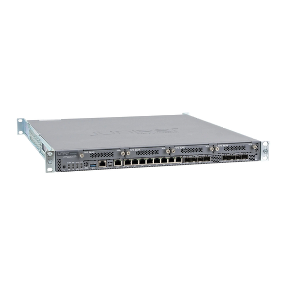
- Page 7 Figure 1: SRX345 Services Gateway ........
- Page 8 SRX345 Services Gateway Hardware Guide viii Copyright © 2017, Juniper Networks, Inc.
- Page 9 Chapter 12 Unpacking the SRX345 Services Gateway ......45 Table 16: Parts List for a Fully Configured SRX345 Services Gateway ..46 Table 17: Accessory Parts List for the SRX345 Services Gateway .
- Page 10 Actions ............90 Table 21: SRX345 Services Gateway Power LED Status ..... 91...
-
Page 11: About The Documentation
® To obtain the most current version of all Juniper Networks technical documentation, see the product documentation page on the Juniper Networks website at http://www.juniper.net/techpubs/ If the information in the latest release notes differs from the information in the documentation, follow the product Release Notes. -
Page 12: Table 1: Notice Icons
SRX345 Services Gateway Hardware Guide Table 1: Notice Icons Icon Meaning Description Informational note Indicates important features or instructions. Caution Indicates a situation that might result in loss of data or hardware damage. Warning Alerts you to the risk of personal injury or death. -
Page 13: Documentation Feedback
We encourage you to provide feedback, comments, and suggestions so that we can improve the documentation. You can provide feedback by using either of the following methods: Online feedback rating system—On any page of the Juniper Networks TechLibrary site , simply click the stars to rate the content, http://www.juniper.net/techpubs/index.html and use the pop-up form to provide us with information about your experience. -
Page 14: Requesting Technical Support
7 days a week, 365 days a year. Self-Help Online Tools and Resources For quick and easy problem resolution, Juniper Networks has designed an online self-service portal called the Customer Support Center (CSC) that provides you with the following features: Find CSC offerings: http://www.juniper.net/customers/support/... - Page 15 About the Documentation For international or direct-dial options in countries without toll-free numbers, see http://www.juniper.net/support/requesting-support.html Copyright © 2017, Juniper Networks, Inc.
- Page 16 SRX345 Services Gateway Hardware Guide Copyright © 2017, Juniper Networks, Inc.
-
Page 17: Overview
PART 1 Overview System Overview on page 3 Chassis Description on page 5 Interface Module Descriptions on page 11 Cooling System Description on page 13 Power System Description on page 15 Copyright © 2017, Juniper Networks, Inc. - Page 18 SRX345 Services Gateway Hardware Guide Copyright © 2017, Juniper Networks, Inc.
-
Page 19: System Overview
The SRX345 Services Gateway has a capacity of 5 gigabits per second (Gbps) and is 1 rack unit (U) tall. The services gateway has eight 1 G Ethernet ports, eight 1 G SFP ports, one management port, 4 GB of DRAM memory, 8 GB of flash memory, and four Mini-Physical Interface Module (Mini-PIM) slots. - Page 20 For more information on the features supported on SRX345 Services Gateways, see Feature Explorer You can manage the SRX345 Services Gateway by using the same interfaces that you use for managing other devices running Junos OS—the CLI, the J-Web graphical interface, and Junos Space.
-
Page 21: Chassis Description
Understanding the SRX345 Services Gateway Back Panel on page 8 SRX345 Services Gateway Chassis Overview The SRX345 Services Gateway chassis is a rigid sheet metal structure that houses all of the other services gateway components. The chassis installs in standard 800–mm (or larger) enclosed cabinets, 19 in. -
Page 22: Figure 2: Srx345 Services Gateway (Single Ac Power Supply) Front Panel
SRX345 Services Gateway Hardware Guide Figure 2: SRX345 Services Gateway (Single AC Power Supply) Front Panel Figure 3 on page 6 shows the front panel of the SRX345 Services Gateway with dual AC power supplies. Figure 3: SRX345 Services Gateway (Dual AC Power Supplies) Front... -
Page 23: Chassis Description
Chapter 2: Chassis Description Table 3: SRX345 Services Gateway Front Panel Components (continued) Callout Component Description 1 G SFP ports Eight 1 G small form-factor pluggable (SFP) ports for network traffic. 1 G Ethernet ports Eight Gigabit Ethernet LAN ports (0/0 to 0/7) -
Page 24: Understanding The Srx345 Services Gateway Back Panel
SRX345 Services Gateway with a single AC power supply and dual AC power supplies respectively. Figure 5: SRX345 Services Gateway Back Panel (Single AC Power Supply) Figure 6: SRX345 Services Gateway Back Panel (Dual AC Power Supplies) Table 5 on page 9 lists the components on the back panel. -
Page 25: Table 5: Srx345 Services Gateway Back Panel Components
Table 6 on page 9 describes the LEDs on the AC power supplies for the SRX345 Services Gateway with dual AC power supplies. Table 6: SRX345 Services Gateway (with Dual AC Power Supplies) Back Panel LEDs LED Color Description Green... - Page 26 SRX345 Services Gateway Hardware Guide Copyright © 2017, Juniper Networks, Inc.
-
Page 27: Interface Module Descriptions
CAUTION: The Mini-PIMs are not hot-swappable. You must power off the services gateway before removing or installing Mini-PIMs. The following Mini-PIMs are supported on the SRX345 Services Gateway: 1-Port Serial Mini-Physical Interface Module (SRX-MP-1SERIAL-R) 1-Port T1/E1 Mini-Physical Interface Module (SRX-MP-1T1E1-R) - Page 28 SRX345 Services Gateway Hardware Guide Copyright © 2017, Juniper Networks, Inc.
-
Page 29: Cooling System Description
Understanding the SRX345 Services Gateway Cooling System on page 13 Understanding the SRX345 Services Gateway Cooling System The cooling system for the SRX345 Services Gateway includes four fixed fans. The fans draw air through vents on the front of the chassis and exhaust the air through the back of the chassis. - Page 30 SRX345 Services Gateway Hardware Guide Understanding the SRX345 Services Gateway Back Panel on page 8 Copyright © 2017, Juniper Networks, Inc.
-
Page 31: Power System Description
Understanding the SRX345 Services Gateway Power Supply on page 15 Understanding the SRX345 Services Gateway Power Supply The SRX345 Services Gateway uses a fixed, internal AC power supply. The power supply distributes the different output voltages to the device components according to their voltage requirements. - Page 32 SRX345 Services Gateway Hardware Guide Copyright © 2017, Juniper Networks, Inc.
-
Page 33: Site Planning And Specifications
Site Planning and Specifications Planning and Preparing the Site on page 19 Rack Requirements on page 25 Cabinet Requirements on page 31 Power Requirements and Specifications on page 33 Cable Specifications and Pinouts on page 37 Copyright © 2017, Juniper Networks, Inc. - Page 34 SRX345 Services Gateway Hardware Guide Copyright © 2017, Juniper Networks, Inc.
-
Page 35: Planning And Preparing The Site
SRX345 Services Gateway Environmental Specifications on page 19 Site Preparation Checklist for the SRX345 Services Gateway on page 20 General Site Installation Guidelines for the SRX345 Services Gateway on page 22 SRX345 Services Gateway Physical Specifications Table 7 on page 19 lists the physical specifications for the services gateway. -
Page 36: Site Preparation Checklist For The Srx345 Services Gateway
SRX345 Services Gateway Hardware Guide Table 8: Environmental Specifications for the SRX345 Services Gateway Description Value Altitude No performance degradation up to 10,000 ft (3048 m) Relative humidity 5% to 95%, noncondensing Temperature Operational temperature—32° F (0° C) to 104° F (40° C) Nonoperational temperature—4°... - Page 37 Chapter 6: Planning and Preparing the Site Table 9: Site Preparation Checklist for SRX345 Services Gateway Installation (continued) Additional Item or Task Information Performed By Date Notes Locate sites for “Connecting the connection of system SRX345 grounding. Services Gateway Grounding Cable”...
-
Page 38: General Site Installation Guidelines For The Srx345 Services Gateway
Plan the cable routing and management. Related General Site Installation Guidelines for the SRX345 Services Gateway on page 22 Documentation General Site Installation Guidelines for the SRX345 Services Gateway The following precautions help you plan an acceptable operating environment for your... - Page 39 Chapter 6: Planning and Preparing the Site Related Site Preparation Checklist for the SRX345 Services Gateway on page 20 Documentation Copyright © 2017, Juniper Networks, Inc.
- Page 40 SRX345 Services Gateway Hardware Guide Copyright © 2017, Juniper Networks, Inc.
-
Page 41: Rack Requirements
SRX345 Services Gateway Rack-Mounting Requirements and Warnings on page 25 SRX345 Services Gateway Rack Size and Strength Requirements on page 29 SRX345 Services Gateway Spacing of Mounting Brackets and Flange Holes on page 29 SRX345 Services Gateway Clearance Requirements for Airflow and Hardware... - Page 42 Les directives ci-dessous sont destinées à assurer la protection du personnel: Le rack sur lequel est monté le Juniper Networks services gateway doit être fixé à la structure du bâtiment. Si cette unité constitue la seule unité montée en casier, elle doit être placée dans le bas.
- Page 43 Le seguenti direttive vengono fornite per garantire la sicurezza personale: Il Juniper Networks services gateway deve essere installato in un telaio, il quale deve essere fissato alla struttura dell'edificio. Questa unità deve venire montata sul fondo del supporto, se si tratta dell'unica unità...
- Page 44 Om ställningen är försedd med stabiliseringsdon skall dessa monteras fast innan enheten installeras eller underhålls på ställningen. Related SRX345 Services Gateway Rack Size and Strength Requirements on page 29 Documentation Copyright © 2017, Juniper Networks, Inc.
-
Page 45: Srx345 Services Gateway Rack Size And Strength Requirements
Chapter 7: Rack Requirements SRX345 Services Gateway Spacing of Mounting Brackets and Flange Holes on page 29 SRX345 Services Gateway Clearance Requirements for Airflow and Hardware Maintenance on page 30 SRX345 Services Gateway Rack Size and Strength Requirements When installing the services gateway in a rack, you must ensure that the rack complies with a 1U (19 in. -
Page 46: Srx345 Services Gateway Clearance Requirements For Airflow And Hardware
SRX345 Services Gateway Clearance Requirements for Airflow and Hardware Maintenance When planning the installation site for the SRX345 Services Gateway, you need to allow sufficient clearance around the device. Consider the following: For the operating temperature of the services gateway to be optimal, the airflow around the chassis must be unrestricted. -
Page 47: Cabinet Requirements
SRX345 Services Gateway Cabinet Airflow Requirements on page 31 SRX345 Services Gateway Cabinet Size and Clearance Requirements You can install the SRX345 Services Gateway in a 19 in. (48.7 cm) cabinet as defined in Cabinets, Racks, Panels, and Associated Equipment (document number EIA-310-D) published by the Electronic Industries Alliance ( http://www.ecaus.org/eia/site/index.html... - Page 48 Route and dress all cables to minimize the blockage of airflow to and from the chassis. Related SRX345 Services Gateway Cabinet Airflow Requirements on page 31 Documentation Copyright © 2017, Juniper Networks, Inc.
-
Page 49: Power Requirements And Specifications
CHAPTER 9 Power Requirements and Specifications SRX345 Services Gateway Electrical Wiring Guidelines on page 33 SRX345 Services Gateway Power Specifications and Requirements on page 34 SRX345 Services Gateway Supported AC Power Cords on page 35 SRX345 Services Gateway Electrical Wiring Guidelines... -
Page 50: Srx345 Services Gateway Power Specifications And Requirements
SRX345 Services Gateway Supported AC Power Cords on page 35 General Electrical Safety Guidelines and Warnings on page 131 SRX345 Services Gateway Power Specifications and Requirements The AC power system electrical specifications for the SRX345 Services Gateway are listed in Table 11 on page... -
Page 51: Srx345 Services Gateway Supported Ac Power Cords
Related SRX345 Services Gateway Electrical Wiring Guidelines on page 33 Documentation SRX345 Services Gateway Supported AC Power Cords on page 35 SRX345 Services Gateway Supported AC Power Cords WARNING: The AC power cord for the services gateway is intended for use with the services gateway only and not for any other use. - Page 52 SRX345 Services Gateway Hardware Guide Related SRX345 Services Gateway Electrical Wiring Guidelines on page 33 Documentation SRX345 Services Gateway Power Specifications and Requirements on page 34 Copyright © 2017, Juniper Networks, Inc.
-
Page 53: Cable Specifications And Pinouts
CHAPTER 10 Cable Specifications and Pinouts RJ-45 Connector Pinouts for the SRX345 Services Gateway Ethernet Port on page 37 RJ-45 Connector Pinouts for the SRX345 Services Gateway Console Port on page 37 Mini-USB Connector Pinouts for the SRX345 Services Gateway Console Port on page 38... -
Page 54: Mini-Usb Connector Pinouts For The Srx345 Services Gateway Console Port
Mini-USB Connector Pinouts for the SRX345 Services Gateway Console Port on page 38 Mini-USB Connector Pinouts for the SRX345 Services Gateway Console Port The SRX345 Services Gateway has two console ports: an RJ-45 Ethernet port and a mini-USB Type-B port. If your management device (laptop or PC) does not have a DB-9... - Page 55 Black Ground Related RJ-45 Connector Pinouts for the SRX345 Services Gateway Ethernet Port on page 37 Documentation RJ-45 Connector Pinouts for the SRX345 Services Gateway Console Port on page 37 Copyright © 2017, Juniper Networks, Inc.
- Page 56 SRX345 Services Gateway Hardware Guide Copyright © 2017, Juniper Networks, Inc.
-
Page 57: Initial Installation And Configuration
Unpacking the SRX345 Services Gateway on page 45 Installing the Rack Mounting Hardware on page 49 Installing the SRX345 Services Gateway in a Rack on page 51 Connecting the SRX345 Services Gateway to Ground on page 55 Connecting the SRX345 Services Gateway to External Devices on page 59... - Page 58 SRX345 Services Gateway Hardware Guide Copyright © 2017, Juniper Networks, Inc.
-
Page 59: Installation Overview
CHAPTER 11 Installation Overview SRX345 Services Gateway Installation Overview on page 43 Required Tools and Parts for Installing the SRX345 Services Gateway on page 43 SRX345 Services Gateway Autoinstallation Overview on page 44 SRX345 Services Gateway Installation Overview After you have prepared the site for installation and unpacked the SRX345 Services Gateway, you are ready to install the device. -
Page 60: Srx345 Services Gateway Autoinstallation Overview
Installation and Upgrade Guide for Security Devices Network Monitoring and Troubleshooting Guide Related SRX345 Services Gateway Installation Overview on page 43 Documentation Required Tools and Parts for Installing the SRX345 Services Gateway on page 43 Copyright © 2017, Juniper Networks, Inc. -
Page 61: Unpacking The Srx345 Services Gateway
Phillips (+) screwdriver, number 2 Blank panels to cover any slots not occupied by a component The SRX345 Services Gateway is shipped in a cardboard carton and secured with foam packing material. The carton also contains an accessory box and quick start instructions. -
Page 62: Verifying Parts Received With The Srx345 Services Gateway
Documentation Verifying Parts Received with the SRX345 Services Gateway The SRX345 Services Gateway shipment package contains a packing list. Check the parts in the shipment against the items on the packing list. The packing list specifies the part numbers and carries a brief description of each part in your order. -
Page 63: Table 17: Accessory Parts List For The Srx345 Services Gateway
Juniper Networks Product Warranty and RoHS Card End User License Agreement How To Set Up Your SRX345 Services Gateway Safety Guide Related Preparing the SRX345 Services Gateway for Rack-Mount Installation on page 49 Documentation Copyright © 2017, Juniper Networks, Inc. - Page 64 SRX345 Services Gateway Hardware Guide Copyright © 2017, Juniper Networks, Inc.
-
Page 65: Installing The Rack Mounting Hardware
Documentation Connecting the SRX345 Services Gateway to the Building Structure Always secure the rack in which you are installing the SRX345 High Memory Services Gateway to the structure of the building. If your geographical area is subject to Copyright © 2017, Juniper Networks, Inc. - Page 66 For maximum stability, also secure the rack to ceiling brackets. Related Installing the SRX345 Services Gateway into a Rack on page 51 Documentation Preparing the SRX345 Services Gateway for Rack-Mount Installation on page 49...
-
Page 67: Installing The Srx345 Services Gateway In A Rack
Installing the SRX345 Services Gateway into a Rack on page 51 Installing the SRX345 Services Gateway into a Rack You can front-mount the SRX345 Services Gateway in a rack. Many types of racks are acceptable, including four-post (telco) racks, enclosed cabinets, and open-frame racks. -
Page 68: Figure 10: Installing The Rack Mount Brackets (Center Mount Position)
SRX345 Services Gateway Hardware Guide Figure 10: Installing the Rack Mount Brackets (Center Mount Position) Have one person grasp the sides of the services gateway, lift it, and position it in the rack. Align the bottom hole in each mounting bracket with a hole in each rack rail, making sure the chassis is level. - Page 69 Chapter 14: Installing the SRX345 Services Gateway in a Rack Related Connecting the SRX345 Services Gateway Grounding Cable on page 56 Documentation Connecting the SRX345 Services Gateway to an AC Power Supply on page 63 Copyright © 2017, Juniper Networks, Inc.
- Page 70 SRX345 Services Gateway Hardware Guide Copyright © 2017, Juniper Networks, Inc.
-
Page 71: Connecting The Srx345 Services Gateway To Ground
CHAPTER 15 Connecting the SRX345 Services Gateway to Ground Required Tools and Parts for Grounding the SRX345 Services Gateway on page 55 SRX345 Services Gateway Grounding Specifications on page 55 Connecting the SRX345 Services Gateway Grounding Cable on page 56... -
Page 72: Connecting The Srx345 Services Gateway Grounding Cable
Grounding lug Ring-type, vinyl-insulated TV14-6R lug or equivalent Related Required Tools and Parts for Grounding the SRX345 Services Gateway on page 55 Documentation Connecting the SRX345 Services Gateway Grounding Cable on page 56 Connecting the SRX345 Services Gateway Grounding Cable The services gateway must be connected to earth ground during normal operation. -
Page 73: Figure 12: Connecting The Grounding Cable To The Srx345 Services Gateway
NOTE: The device should be permanently connected to ground during operation. Related Required Tools and Parts for Grounding the SRX345 Services Gateway on page 55 Documentation SRX345 Services Gateway Grounding Specifications on page 55 Copyright © 2017, Juniper Networks, Inc. - Page 74 SRX345 Services Gateway Hardware Guide Copyright © 2017, Juniper Networks, Inc.
-
Page 75: Connecting The Srx345 Services Gateway To External Devices
Connecting the Dial-Up Modem to the Console Port on the SRX345 Services Gateway on page 59 Connecting to the SRX345 Services Gateway CLI Using a Dial-Up Modem on page 60 Connecting the Dial-Up Modem to the Console Port on the SRX345 Services Gateway To connect the dial-up modem to the console port on the services gateway: Turn off power to the services gateway. -
Page 76: Connecting To The Srx345 Services Gateway Cli Using A Dial-Up Modem
RJ-45 to DB-9 adapter and the Ethernet cable supplied with the services gateway. Related Connecting to the SRX345 Services Gateway CLI Using a Dial-Up Modem on page 60 Documentation Connecting to the SRX345 Services Gateway CLI Using a Dial-Up Modem... - Page 77 Log in as the root user. No password is required at initial connection, but you must assign a root password before committing any configuration settings. Related Connecting the Dial-Up Modem to the Console Port on the SRX345 Services Gateway Documentation on page 59...
- Page 78 SRX345 Services Gateway Hardware Guide Copyright © 2017, Juniper Networks, Inc.
-
Page 79: Providing Power To The Srx345 Services Gateway
CHAPTER 17 Providing Power to the SRX345 Services Gateway Connecting the SRX345 Services Gateway to an AC Power Supply on page 63 Powering On the SRX345 Services Gateway on page 64 Powering Off the SRX345 Services Gateway on page 65... -
Page 80: Powering On The Srx345 Services Gateway
SRX345 Services Gateway Hardware Guide Figure 13: Connecting the SRX345 Services Gateway to an AC Power Supply If you are using a SRX345 Services Gateway with dual AC power supplies, then repeat steps 1 through 3 for the second power supply. CAUTION: We recommend using a surge protector for the power connection. -
Page 81: Powering Off The Srx345 Services Gateway
CLI command. request system power-off Related Connecting the SRX345 Services Gateway to an AC Power Supply on page 63 Documentation Powering Off the SRX345 Services Gateway on page 65 Powering Off the SRX345 Services Gateway You can power off the services gateway in one of the following ways: Graceful shutdown—Press and immediately release the Power button. - Page 82 You can use the request system reboot CLI command to schedule a reboot. Related Connecting the SRX345 Services Gateway to an AC Power Supply on page 63 Documentation Powering On the SRX345 Services Gateway on page 64 Copyright © 2017, Juniper Networks, Inc.
-
Page 83: Performing The Initial Configuration
Configuring Zero-Touch Provisioning on the SRX345 Services Gateway on page 70 Accessing J-Web on the SRX345 Services Gateway on page 71 Configuring the SRX345 Services Gateway Using the J-Web Setup Wizard on page 72 Accessing the CLI on the SRX345 Services Gateway on page 76... -
Page 84: Understanding Srx345 Services Gateway Factory-Default Settings
SRX345 Services Gateway Hardware Guide Connecting to the SRX345 Services Gateway from the CLI Remotely on page 77 Configuring the SRX345 Services Gateway Using the CLI on page 78 Understanding SRX345 Services Gateway Factory-Default Settings Your services gateway comes configured with a factory-default configuration. The default configuration includes the following security configuration: Two security zones are created: trust and untrust. -
Page 85: Viewing Srx345 Services Gateway Factory-Default Settings
Chapter 18: Performing the Initial Configuration Viewing SRX345 Services Gateway Factory-Default Settings To view the factory-default configuration of the services gateway using the CLI: Verify that the services gateway is powered on. Log in as the root user and provide your credentials. -
Page 86: Configuring Zero-Touch Provisioning On The Srx345 Services Gateway
Understanding SRX345 Services Gateway Factory-Default Settings on page 68 Accessing J-Web on the SRX345 Services Gateway on page 71 Configuring the SRX345 Services Gateway Using the J-Web Setup Wizard on page 72 Accessing the CLI on the SRX345 Services Gateway on page 76... -
Page 87: Accessing J-Web On The Srx345 Services Gateway
“Configuring the SRX345 Services Gateway Using the J-Web Setup Wizard” on page Related Configuring the SRX345 Services Gateway Using the J-Web Setup Wizard on page 72 Documentation Accessing J-Web on the SRX345 Services Gateway The J-Web interface is a Web-based graphical interface that allows you to operate a services gateway without commands. -
Page 88: Configuring The Srx345 Services Gateway Using The J-Web Setup Wizard
Understanding SRX345 Services Gateway Factory-Default Settings on page 68 Viewing SRX345 Services Gateway Factory-Default Settings on page 69 Configuring the SRX345 Services Gateway Using the J-Web Setup Wizard on page 72 Accessing the CLI on the SRX345 Services Gateway on page 76... -
Page 89: About The Setup Wizard
Password for the root account Time information for the services gateway location: Local time zone Name or IP address of a Network Time Protocol (NTP) server, if NTP is used to set the time on the services gateway Copyright © 2017, Juniper Networks, Inc. -
Page 90: About The Guided Setup Mode
SRX345 Services Gateway Hardware Guide Local date and time if an NTP server is not used to set the time Management interface You cannot do additional configuration in the Default Setup mode. You must commit your changes and exit the wizard to perform any additional configuration. You can perform additional configuration by rerunning the wizard in the Guided Setup mode, by using the J-Web interface, or by using the CLI. - Page 91 Confirm & Apply page to reconnect, if required. Click to complete the setup. Done After you finish configuring the services gateway with the setup wizard and commit your configuration, you are redirected to the J-Web interface. Thereafter, whenever you connect Copyright © 2017, Juniper Networks, Inc.
-
Page 92: Accessing The Cli On The Srx345 Services Gateway
Accessing J-Web on the SRX345 Services Gateway on page 71 Accessing the CLI on the SRX345 Services Gateway on page 76 Connecting to the SRX345 Services Gateway from the CLI Remotely on page 77 Configuring the SRX345 Services Gateway Using the CLI on page 78... -
Page 93: Connecting To The Srx345 Services Gateway From The Cli Remotely
Viewing SRX345 Services Gateway Factory-Default Settings on page 69 Accessing J-Web on the SRX345 Services Gateway on page 71 Configuring the SRX345 Services Gateway Using the J-Web Setup Wizard on page 72 Connecting to the SRX345 Services Gateway from the CLI Remotely on page 77... -
Page 94: Configuring The Srx345 Services Gateway Using The Cli
Viewing SRX345 Services Gateway Factory-Default Settings on page 69 Accessing J-Web on the SRX345 Services Gateway on page 71 Configuring the SRX345 Services Gateway Using the J-Web Setup Wizard on page 72 Accessing the CLI on the SRX345 Services Gateway on page 76... - Page 95 The ge-0/0/0 interface is for the ISP, and the ge-0/0/1 interface is for the LAN. Configure the default route. [edit] admin# set routing-options static route 0.0.0.0/0 next-hop gateway Configure basic security zones and bind them to traffic interfaces. [edit] Copyright © 2017, Juniper Networks, Inc.
- Page 96 SRX345 Services Gateway Hardware Guide admin# set security zones security-zone untrust interfaces ge-0/0/0 admin# set security zones security-zone trust interfaces ge-0/0/1 admin# set security zones security-zone trust interfaces ge-0/0/1.0 host-inbound-traffic system-services all admin# set security zones security-zone trust interfaces ge-0/0/1.0 host-inbound-traffic protocols all Configure basic security policies.
- Page 97 Viewing SRX345 Services Gateway Factory-Default Settings on page 69 Accessing J-Web on the SRX345 Services Gateway on page 71 Configuring the SRX345 Services Gateway Using the J-Web Setup Wizard on page 72 Accessing the CLI on the SRX345 Services Gateway on page 76 Connecting to the SRX345 Services Gateway from the CLI Remotely on page 77 Copyright ©...
- Page 98 SRX345 Services Gateway Hardware Guide Copyright © 2017, Juniper Networks, Inc.
-
Page 99: Maintaining And Troubleshooting Components
PART 4 Maintaining and Troubleshooting Components Maintaining Components on page 85 Troubleshooting Components on page 89 Copyright © 2017, Juniper Networks, Inc. - Page 100 SRX345 Services Gateway Hardware Guide Copyright © 2017, Juniper Networks, Inc.
-
Page 101: Maintaining Components
CHAPTER 19 Maintaining Components Required Tools and Parts for Maintaining the SRX345 Services Gateway Hardware Components on page 85 Routine Maintenance Procedures for the SRX345 Services Gateway on page 85 Maintaining the SRX345 Services Gateway Cooling System Components on page 86... -
Page 102: Maintaining The Srx345 Services Gateway Cooling System Components
Periodically inspect the site to ensure that the power cables connected to the services gateway are securely in place and that there is no moisture accumulating near the services gateway. To check the status of the power supplies on an SRX345 Services Gateway with dual AC power supplies, use the show chassis environment show chassis hardware command. - Page 103 8xGE,8xGE SFP Base PIC Power Supply 1 NOTE: If one of the power supplies on an SRX345 Services Gateway with dual AC power supplies has failed, the output of the show chassis hardware command displays only the power supply that is operational.
- Page 104 SRX345 Services Gateway Hardware Guide Copyright © 2017, Juniper Networks, Inc.
-
Page 105: Troubleshooting Components
Gateway on page 90 Troubleshooting the Power System on the SRX345 Services Gateway on page 91 Using the RESET CONFIG Button on the SRX345 Services Gateway on page 92 Changing the RESET CONFIG Button Behavior on the SRX345 Services Gateway on page 93... -
Page 106: Troubleshooting Chassis And Interface Alarm Messages On The Srx345 Services
SRX345 Services Gateway Hardware Guide Troubleshooting Chassis and Interface Alarm Messages on the SRX345 Services Gateway When the services gateway detects an alarm condition, the alarm LED on the front panel turns red or amber as appropriate. To view a more detailed description of the alarm cause, issue the CLI command. -
Page 107: Troubleshooting The Power System On The Srx345 Services Gateway
Documentation Troubleshooting the Power System on the SRX345 Services Gateway on page 91 Using the RESET CONFIG Button on the SRX345 Services Gateway on page 92 Changing the RESET CONFIG Button Behavior on the SRX345 Services Gateway on page 93... -
Page 108: Using The Reset Config Button On The Srx345 Services Gateway
JTAC. The SRX345 Services Gateway with dual AC power supplies provides a system alarm that alerts you when one of the power supplies fails. You can display the messages for this alarm by issuing the... -
Page 109: Changing The Reset Config Button Behavior On The Srx345 Services Gateway
Troubleshooting Chassis and Interface Alarm Messages on the SRX345 Services Gateway on page 90 Troubleshooting the Power System on the SRX345 Services Gateway on page 91 Changing the RESET CONFIG Button Behavior on the SRX345 Services Gateway on page 93... -
Page 110: Using The Reset Config Button On The Srx345 Services Gateway
Troubleshooting Chassis and Interface Alarm Messages on the SRX345 Services Gateway on page 90 Troubleshooting the Power System on the SRX345 Services Gateway on page 91 Using the RESET CONFIG Button on the SRX345 Services Gateway on page 92 Copyright © 2017, Juniper Networks, Inc. -
Page 111: Replacing Components
PART 5 Replacing Components Overview of Replacing Components on page 97 Replacing Interface Modules on page 99 Contacting Customer Support and Returning Components on page 101 Copyright © 2017, Juniper Networks, Inc. - Page 112 SRX345 Services Gateway Hardware Guide Copyright © 2017, Juniper Networks, Inc.
-
Page 113: Overview Of Replacing Components
SRX345 Services Gateway Field Replaceable Units Overview Field-replaceable units (FRUs) are components that you can replace at your site. The Mini-Physical Interface Module (MPIM) is the only FRU on the SRX345 Services Gateway. The Mini-PIMs are not hot-swappable. You must power off the services gateway before removing or installing Mini-PIMs. - Page 114 SRX345 Services Gateway Hardware Guide Copyright © 2017, Juniper Networks, Inc.
-
Page 115: Replacing Interface Modules
CHAPTER 22 Replacing Interface Modules Replacing Mini-Physical Interface Modules in the SRX345 Services Gateway on page 99 Replacing Mini-Physical Interface Modules in the SRX345 Services Gateway The Mini-PIMs available on the SRX345 Services Gateway are not hot-swappable. You need to power off the device before removing or installing Mini-PIMs. For information on... - Page 116 SRX345 Services Gateway Hardware Guide Copyright © 2017, Juniper Networks, Inc.
-
Page 117: Contacting Customer Support And Returning Components
Contacting Customer Support Once you have located the serial numbers of the device or component, you can return the device or component for repair or replacement. For this, you need to contact Juniper Networks Technical Assistance Center (JTAC). You can contact JTAC 24 hours a day, 7 days a week, using any of the following methods: On the Web: Using the Case Manager link at http://www.juniper.net/support/... -
Page 118: Returning A Srx345 Services Gateway Component To Juniper Networks
Packing SRX345 Services Gateway Components for Shipment on page 107 Returning a SRX345 Services Gateway Component to Juniper Networks To return an SRX345 Services Gateway or component to Juniper Networks for repair or replacement: Determine the part number and serial number of the services gateway or component. -
Page 119: Locating The Srx345 Services Gateway Chassis Serial Number And Agency
Chapter 23: Contacting Customer Support and Returning Components Information You Might Need to Supply to JTAC on page 104 Required Tools and Parts for Packing the SRX345 Services Gateway on page 105 Packing the SRX345 Services Gateway for Shipment on page 106... -
Page 120: Listing The Srx345 Services Gateway Component Details With The Cli
Before contacting Juniper Networks to request an RMA, you must find the serial number on the SRX345 Services Gateway or component. To list all of the SRX345 Services Gateway components and their serial numbers, enter the following command: user@host> show chassis hardware... -
Page 121: Required Tools And Parts For Packing The Srx345 Services Gateway
Packing SRX345 Services Gateway Components for Shipment on page 107 Required Tools and Parts for Packing the SRX345 Services Gateway To remove the components from the SRX345 Services Gateway or to remove the services gateway from a rack, you need the following tools and parts:... -
Page 122: Packing The Srx345 Services Gateway For Shipment
To pack the SRX345 Services Gateway for shipment: Retrieve the shipping carton and packing materials in which the services gateway was originally shipped. If you do not have these materials, contact your Juniper Networks representative about approved packaging materials. Attach an electrostatic discharge (ESD) grounding strap to your bare wrist and connect the strap to the ESD point on the chassis or to an outside ESD point if the device is disconnected from earth ground. -
Page 123: Packing Srx345 Services Gateway Components For Shipment
Locating the SRX345 Services Gateway Mini-Physical Interface Module Serial Number Label on page 103 Listing the SRX345 Services Gateway Component Details with the CLI on page 104 Information You Might Need to Supply to JTAC on page 104 Required Tools and Parts for Packing the SRX345 Services Gateway on page 105... - Page 124 SRX345 Services Gateway Hardware Guide Copyright © 2017, Juniper Networks, Inc.
-
Page 125: Part 6 Safety And Regulatory Compliance Information
Laser and LED Safety Guidelines and Warnings on page 121 Maintenance and Operational Safety Guidelines and Warnings on page 125 Electrical Safety Guidelines and Warnings on page 131 Agency Approvals and Regulatory Compliance Information on page 135 Copyright © 2017, Juniper Networks, Inc. - Page 126 SRX345 Services Gateway Hardware Guide Copyright © 2017, Juniper Networks, Inc.
-
Page 127: General Safety Guidelines And Warnings
Voordat u aan enige apparatuur gaat werken, dient u zich bewust te zijn van de bij elektrische schakelingen betrokken risico's en dient u op de hoogte te zijn van standaard maatregelen om ongelukken te voorkomen. Copyright © 2017, Juniper Networks, Inc. - Page 128 SRX345 Services Gateway Hardware Guide Varoitus Tämä varoitusmerkki merkitsee vaaraa. Olet tilanteessa, joka voi johtaa ruumiinvammaan. Ennen kuin työskentelet minkään laitteiston parissa, ota selvää sähkökytkentöihin liittyvistä vaaroista ja tavanomaisista onnettomuuksien ehkäisykeinoista. Attention Ce symbole d'avertissement indique un danger. Vous vous trouvez dans une situation pouvant causer des blessures ou des dommages corporels.
-
Page 129: General Safety Guidelines And Warnings
Do not push or force any objects through any opening in the chassis frame. Such an action could result in electrical shock or fire. Avoid spilling liquid onto the chassis or onto any device component. Such an action could cause electrical shock or damage the device. Copyright © 2017, Juniper Networks, Inc. -
Page 130: Restricted Access Warning
SRX345 Services Gateway Hardware Guide Avoid touching uninsulated electrical wires or terminals that have not been disconnected from their power source. Such an action could cause electrical shock. Always ensure that all modules, power supplies, and cover panels are fully inserted and that the installation screws are fully tightened. -
Page 131: Qualified Personnel Warning
Waarschuwing Installatie en reparaties mogen uitsluitend door getraind en bevoegd personeel uitgevoerd worden. Varoitus Ainoastaan koulutettu ja pätevä henkilökunta saa asentaa tai vaihtaa tämän laitteen. Attention Tout installation ou remplacement de l'appareil doit être réalisé par du personnel qualifié et compétent. Copyright © 2017, Juniper Networks, Inc. -
Page 132: Prevention Of Electrostatic Discharge Damage
SRX345 Services Gateway Hardware Guide Warnung Gerät nur von geschultem, qualifiziertem Personal installieren oder auswechseln lassen. Avvertenza Solo personale addestrato e qualificato deve essere autorizzato ad installare o sostituire questo apparecchio. Advarsel Kun kvalifisert personell med riktig opplæring bør montere eller bytte ut dette utstyret. -
Page 133: Figure 16: Placing A Component Into An Antistatic Bag
To dissipate this charge, always ground the cables to a suitable and safe earth ground before connecting them to the system. Related General Safety Guidelines and Warnings on page 113 Documentation Copyright © 2017, Juniper Networks, Inc. - Page 134 SRX345 Services Gateway Hardware Guide Copyright © 2017, Juniper Networks, Inc.
-
Page 135: Fire Safety Requirements
In addition, you should establish procedures to protect your equipment in the event of a fire emergency. Juniper Networks products should be installed in an environment suitable for electronic equipment. We recommend that fire suppression equipment be available in the event of a fire in the vicinity of the equipment and that all local fire, safety, and electrical codes and ordinances be observed when you install and operate your equipment. - Page 136 To keep warranties effective, do not use a dry chemical fire extinguisher to control a fire at or near a Juniper Networks device. If a dry chemical fire extinguisher is used, the unit is no longer eligible for coverage under a service agreement.
-
Page 137: Laser And Led Safety Guidelines And Warnings
Radiation from Open Port Apertures Warning on page 123 Laser and LED Safety Guidelines and Warnings Juniper Networks devices are equipped with laser transmitters, which are considered a Class 1 Laser Product by the U.S. Food and Drug Administration and are evaluated as a Class 1 Laser Product per EN 60825-1 requirements. -
Page 138: Class 1 Laser Product Warning
SRX345 Services Gateway Hardware Guide Class 1 Laser Product Warning WARNING: Class 1 laser product. Waarschuwing Klasse-1 laser produkt. Varoitus Luokan 1 lasertuote. Attention Produit laser de classe I. Warnung Laserprodukt der Klasse 1. Avvertenza Prodotto laser di Classe 1. -
Page 139: Radiation From Open Port Apertures Warning
Varoitus Koska portin aukosta voi emittoitua näkymätöntä säteilyä, kun kuitukaapelia ei ole kytkettynä, vältä säteilylle altistumista äläkä katso avoimiin aukkoihin. Copyright © 2017, Juniper Networks, Inc. - Page 140 SRX345 Services Gateway Hardware Guide Attention Des radiations invisibles à l'il nu pouvant traverser l'ouverture du port lorsqu'aucun câble en fibre optique n'y est connecté, il est recommandé de ne pas regarder fixement l'intérieur de ces ouvertures. Warnung Aus der Port-Öffnung können unsichtbare Strahlen emittieren, wenn kein Glasfaserkabel angeschlossen ist.
-
Page 141: Maintenance And Operational Safety Guidelines And Warnings
Attention Danger d'explosion si la pile n'est pas remplacée correctement. Ne la remplacer que par une pile de type semblable ou équivalent, recommandée par le fabricant. Jeter les piles usagées conformément aux instructions du fabricant. Copyright © 2017, Juniper Networks, Inc. -
Page 142: Jewelry Removal Warning
SRX345 Services Gateway Hardware Guide Warnung Bei Einsetzen einer falschen Batterie besteht Explosionsgefahr. Ersetzen Sie die Batterie nur durch den gleichen oder vom Hersteller empfohlenen Batterietyp. Entsorgen Sie die benutzten Batterien nach den Anweisungen des Herstellers. Advarsel Det kan være fare for eksplosjon hvis batteriet skiftes på feil måte. -
Page 143: Lightning Activity Warning
Waarschuwing Tijdens onweer dat gepaard gaat met bliksem, dient u niet aan het systeem te werken of kabels aan te sluiten of te ontkoppelen. Varoitus Älä työskentele järjestelmän parissa äläkä yhdistä tai irrota kaapeleita ukkosilmalla. Copyright © 2017, Juniper Networks, Inc. -
Page 144: Operating Temperature Warning
6 in. (15.2 cm) of clearance around the ventilation openings. Waarschuwing Om te voorkomen dat welke switch van de Juniper Networks router dan ook oververhit raakt, dient u deze niet te bedienen op een plaats waar de maximale aanbevolen omgevingstemperatuur van 40°... -
Page 145: Product Disposal Warning
15,2 cm à volta das aberturas de ventilação. ¡Atención! Para impedir que un encaminador de la serie Juniper Networks switch se recaliente, no lo haga funcionar en un área en la que se supere la temperatura ambiente máxima recomendada de 40°... - Page 146 SRX345 Services Gateway Hardware Guide Advarsel Endelig disponering av dette produktet må skje i henhold til nasjonale lover og forskrifter. Aviso A descartagem final deste produto deverá ser efectuada de acordo com os regulamentos e a legislação nacional. ¡Atención! El desecho final de este producto debe realizarse según todas las leyes y regulaciones nacionales Varning! Slutlig kassering av denna produkt bör skötas i enlighet med landets...
-
Page 147: Electrical Safety Guidelines And Warnings
Install the services gateway in compliance with the following local, national, or international electrical codes: United States—National Fire Protection Association (NFPA 70), United States National Electrical Code Canada—Canadian Electrical Code, Part 1, CSA C22.1 Copyright © 2017, Juniper Networks, Inc. -
Page 148: Ac Power Electrical Safety Guidelines
SRX345 Services Gateway Hardware Guide Other countries—International Electromechanical Commission (IEC) 60364, Part 1 through Part 7 Evaluated to the TN power system Locate the emergency power-off switch for the room in which you are working so that if an electrical accident occurs, you can quickly turn off the power. - Page 149 The attached power cable is only for this product. Do not use the cable for another product. Related General Safety Guidelines and Warnings on page 113 Documentation General Electrical Safety Guidelines and Warnings Multiple Power Supplies Disconnection Warning Copyright © 2017, Juniper Networks, Inc.
- Page 150 SRX345 Services Gateway Hardware Guide Copyright © 2017, Juniper Networks, Inc.
-
Page 151: Agency Approvals And Regulatory Compliance Information
Agency Approvals and Regulatory Compliance Information SRX345 Services Gateway Agency Approvals on page 135 SRX345 Services Gateway Acoustic Noise Compliance Statements on page 136 SRX345 Services Gateway EMC Requirements on page 137 SRX345 Services Gateway Agency Approvals The services gateway complies with the following standards: Safety CAN/CSA-C22.2 No.60950-1 (2007) Information Technology Equipment... -
Page 152: Srx345 Services Gateway Acoustic Noise Compliance Statements
Reduction of Hazardous Substances (ROHS) 6 Telco Common Language Equipment Identifier (CLEI) code Related SRX345 Services Gateway Acoustic Noise Compliance Statements on page 136 Documentation SRX345 Services Gateway EMC Requirements on page 137 SRX345 Services Gateway Acoustic Noise Compliance Statements The maximum emitted sound pressure level is 70 dB(A) or less per EN ISO 7779. -
Page 153: Srx345 Services Gateway Emc Requirements
Chapter 29: Agency Approvals and Regulatory Compliance Information SRX345 Services Gateway EMC Requirements Canada This Class A digital apparatus complies with Canadian ICES-003. Cet appareil numérique de la classe A est conforme à la norme NMB-003 du Canada. European Community This is a Class A product. - Page 154 SRX345 Services Gateway Hardware Guide Related SRX345 Services Gateway Agency Approvals on page 135 Documentation SRX345 Services Gateway Acoustic Noise Compliance Statements on page 136 Copyright © 2017, Juniper Networks, Inc.