Juniper SRX345 Hardware Manual
Services gateway
Hide thumbs
Also See for SRX345:
- Hardware manual (154 pages) ,
- Quick start manual (12 pages) ,
- How to set up (10 pages)

Related Manuals for Juniper SRX345


Summary of Contents for Juniper SRX345
- Page 1 SRX345 Services Gateway Hardware Guide Modified: 2019-05-24 Copyright © 2019, Juniper Networks, Inc.
- Page 2 END USER LICENSE AGREEMENT The Juniper Networks product that is the subject of this technical documentation consists of (or is intended for use with) Juniper Networks software. Use of such software is subject to the terms and conditions of the End User License Agreement (“EULA”) posted at https://support.juniper.net/support/eula/.
-
Page 3: Table Of Contents
SRX345 Services Gateway Overview ........ - Page 4 Unpacking and Mounting the SRX345 ........
- Page 5 Maintaining Components ......... . 65 Maintaining the SRX345 Components ........65 Required Tools and Parts for Maintaining the SRX345 Services Gateway Hardware Components .
- Page 6 DC Power Wiring Terminations Warning ......102 SRX345 Services Gateway Agency Approvals ......103 SRX345 Services Gateway Acoustic Noise Compliance Statements .
- Page 7 Figure 1: SRX345 Services Gateway ........
- Page 8 SRX345 Services Gateway Hardware Guide viii Copyright © 2019, Juniper Networks, Inc.
- Page 9 Table 3: SRX345 Services Gateway Front Panel Components ....20 Table 4: SRX345 Services Gateway Front Panel LEDs ..... . 21 Table 5: Management Port LEDs .
- Page 10 SRX345 Services Gateway Hardware Guide Copyright © 2019, Juniper Networks, Inc.
-
Page 11: About The Documentation
® To obtain the most current version of all Juniper Networks technical documentation, see the product documentation page on the Juniper Networks website at https://www.juniper.net/documentation/ If the information in the latest release notes differs from the information in the documentation, follow the product Release Notes. -
Page 12: Merging A Full Example
SRX345 Services Gateway Hardware Guide Merging a Full Example To merge a full example, follow these steps: From the HTML or PDF version of the manual, copy a configuration example into a text file, save the file with a name, and copy the file to a directory on your routing platform. -
Page 13: Documentation Conventions
Alerts you to the risk of personal injury from a laser. Indicates helpful information. Best practice Alerts you to a recommended use or implementation. Table 2 on page xiv defines the text and syntax conventions used in this guide. Copyright © 2019, Juniper Networks, Inc. xiii... -
Page 14: Table 2: Text And Syntax Conventions
SRX345 Services Gateway Hardware Guide Table 2: Text and Syntax Conventions Convention Description Examples Bold text like this Represents text that you type. To enter configuration mode, type the configure command: user@host> configure Fixed-width text like this Represents output that appears on the user@host>... -
Page 15: Documentation Feedback
Requesting Technical Support Technical product support is available through the Juniper Networks Technical Assistance Center (JTAC). If you are a customer with an active Juniper Care or Partner Support Services support contract, or are covered under warranty, and need post-sales technical support, you can access our tools and resources online or open a case with JTAC. -
Page 16: Self-Help Online Tools And Resources
SRX345 Services Gateway Hardware Guide Self-Help Online Tools and Resources For quick and easy problem resolution, Juniper Networks has designed an online self-service portal called the Customer Support Center (CSC) that provides you with the following features: Find CSC offerings: https://www.juniper.net/customers/support/... -
Page 17: Overview
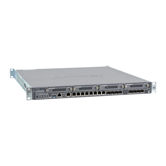
The SRX345 Services Gateway has a capacity of 5 gigabits per second (Gbps) and is 1 rack unit (U) tall. The services gateway has eight 1 G Ethernet ports, eight 1 G SFP ports, one management port, 4 GB of DRAM memory, 8 GB of flash memory, and four Mini-Physical Interface Module (Mini-PIM) slots. -
Page 18: Srx345 Services Gateway Field Replaceable Units Overview
For more information about the features supported on SRX345 Services Gateways, see Feature Explorer You can manage the SRX345 Services Gateway by using the same interfaces that you use for managing other devices that run Junos OS—the CLI, the J-Web graphical interface, and Junos Space. -
Page 19: Srx345 Chassis
SRX345 Services Gateway Interface Modules Overview on page 24 SRX345 Services Gateway Chassis Overview The SRX345 Services Gateway chassis is a rigid sheet metal structure that houses all of the other services gateway components. The chassis installs in standard 800–mm (or larger) enclosed cabinets, 19 in. -
Page 20: Figure 3: Srx345 Services Gateway (Dual Ac Power Supplies) Front Panel
SRX345 Services Gateway Hardware Guide Figure 3: SRX345 Services Gateway (Dual AC Power Supplies) Front Panel FIPS BLNK FIPS BLNK FIPS BLNK FIPS BLNK MPIM MPIM MPIM MPIM Table 3 on page 20 provides details about the front panel components. -
Page 21: Chassis Status Leds
Chapter 1: Overview Table 3: SRX345 Services Gateway Front Panel Components (continued) Callout Component Description 1 G Ethernet ports Eight Gigabit Ethernet LAN ports (0/0 to 0/7) The Gigabit Ethernet ports have the following characteristics: Use an RJ-45 connector Operate in full-duplex and half-duplex modes... -
Page 22: Management Port Leds
SRX345 Services Gateway Hardware Guide Table 4: SRX345 Services Gateway Front Panel LEDs (continued) Component Description Solid green (receiving power) Solid amber (Power-off triggered) Off (no power) Solid green (all HA links are available) Solid amber (some HA links are... -
Page 23: Srx345 Services Gateway Back Panel
Figure 6: SRX345 Services Gateway Back Panel (Dual AC Power Supplies) Figure 7 on page 23 shows the back panel of the SRX345 Services Gateway with a DC power supply. Figure 7: SRX345 Services Gateway Back Panel (DC Power Supply) Table 7 on page 23 lists the components on the back panel. -
Page 24: Srx345 Services Gateway Interface Modules Overview
Documentation SRX345 Cooling System The cooling system for the SRX345 Services Gateway includes four fixed fans. The fans draw air through vents on the front of the chassis and exhaust the air through the back of the chassis. The airflow produced by the fans keeps device components within the acceptable temperature range. -
Page 25: Srx345 Power System
SRX345 Services Gateway Supported AC Power Cords on page 26 SRX345 Services Gateway Power Supply The SRX345 Services Gateway is available with either a single AC power supply (Junos OS Release 15.1X49-D35 and later), dual AC power supplies (Junos OS Release 15.1X49-D110 and later), or a single DC power supply (Junos OS Release 17.4R1 and later). -
Page 26: Srx345 Services Gateway Supported Ac Power Cords
SRX345 Services Gateway Hardware Guide Table 9: Power System Electrical Specifications for the SRX345 Services Gateway (AC Models) Power Requirement Specification AC input voltage 100 to 240 VAC AC input line frequency 50 to 60 Hz AC system current rating 1 to 1.5 A... -
Page 27: Figure 9: Ac Plug Types
Figure 9: AC Plug Types NOTE: Power cords and cables must not block access to services gateway components or drape where people might trip on them. Related SRX345 Services Gateway Electrical Wiring Guidelines on page 32 Documentation Copyright © 2019, Juniper Networks, Inc. - Page 28 SRX345 Services Gateway Hardware Guide Copyright © 2019, Juniper Networks, Inc.
-
Page 29: Site Planning, Preparation, And Specifications
Table 12 on page 29 provides a checklist of tasks you need to perform when preparing a site for installing the SRX345 Services Gateway. Table 12: Site Preparation Checklist for SRX345 Services Gateway Installation m e d f o r... - Page 30 Plan the cable routing and management. Related General Site Installation Guidelines for the SRX345 Services Gateway on page 31 Documentation Copyright © 2019, Juniper Networks, Inc.
-
Page 31: Srx345 Site Guidelines And Requirements
Chapter 2: Site Planning, Preparation, and Specifications SRX345 Site Guidelines and Requirements General Site Installation Guidelines for the SRX345 Services Gateway on page 31 SRX345 Services Gateway Environmental Specifications on page 31 SRX345 Services Gateway Electrical Wiring Guidelines on page 32... -
Page 32: Srx345 Services Gateway Electrical Wiring Guidelines
CAUTION: It is particularly important to provide a properly grounded and shielded environment and to use electrical surge-suppression devices. Table 14: Site Electrical Wiring Guidelines for the SRX345 Services Gateway Site Wiring Factor Guideline Signaling Limitations To ensure that signaling functions optimally: Install wires correctly. -
Page 33: Srx345 Services Gateway Grounding Specifications
SRX345 Services Gateway Grounding Specifications To meet safety and electromagnetic interference (EMI) requirements and to ensure proper operation, the SRX345 Services Gateway must be adequately grounded before power is connected. You must provide a grounding lug to connect the services gateway to earth ground. -
Page 34: Srx345 Services Gateway Clearance Requirements For Airflow And Hardware Maintenance
SRX345 Services Gateway Hardware Guide SRX345 Services Gateway Clearance Requirements for Airflow and Hardware Maintenance When planning the installation site for the SRX345 Services Gateway, you need to allow sufficient clearance around the device. Consider the following: For the operating temperature of the services gateway to be optimal, the airflow around the chassis must be unrestricted. -
Page 35: Cabinet Requirements
SRX345 Transceiver Specifications and Pinouts SRX345 Transceiver Support on page 36 RJ-45 Connector Pinouts for the SRX345 Services Gateway Ethernet Port on page 36 RJ-45 Connector Pinouts for the SRX345 Services Gateway Console Port on page 36 Mini-USB Connector Pinouts for the SRX345 Services Gateway Console Port on page 37... -
Page 36: Srx345 Transceiver Support
The Hardware Compatibility Tool enables you to search by product, displaying all the transceivers supported on that device, or category, by interface speed or type. The list of supported transceivers for the SRX345 is located at https://apps.juniper.net/hct/product/#prd=SRX345... -
Page 37: Port
Clear to Send Mini-USB Connector Pinouts for the SRX345 Services Gateway Console Port The SRX345 Services Gateway has two console ports: an RJ-45 Ethernet port and a mini-USB Type-B port. If your management device (laptop or PC) does not have a DB-9... - Page 38 SRX345 Services Gateway Hardware Guide Copyright © 2019, Juniper Networks, Inc.
-
Page 39: Chapter 3 Initial Installation And Configuration
SRX345 Services Gateway Autoinstallation Overview on page 40 SRX345 Services Gateway Installation Overview After you have prepared the site for installation and unpacked the SRX345 Services Gateway, you are ready to install the device. It is important to proceed through the... -
Page 40: Srx345 Services Gateway Autoinstallation Overview
SRX345 Services Gateway Hardware Guide SRX345 Services Gateway Autoinstallation Overview The autoinstallation process begins any time a services gateway is powered on and cannot locate a valid configuration file in the internal flash. Typically, a configuration file is unavailable when a services gateway is powered on for the first time or if the configuration file is deleted from the internal flash. -
Page 41: Unpacking And Mounting The Srx345
Phillips (+) screwdriver, number 2 Blank panels to cover any slots not occupied by a component The SRX345 Services Gateway is shipped in a cardboard carton and secured with foam packing material. The carton also contains an accessory box and quick start instructions. -
Page 42: Verifying Parts Received With The Srx345 Services Gateway
SRX345 Services Gateway Hardware Guide Verifying Parts Received with the SRX345 Services Gateway The SRX345 Services Gateway shipment package contains a packing list. Check the parts in the shipment against the items on the packing list. The packing list specifies the part numbers and carries a brief description of each part in your order. -
Page 43: Preparing The Srx345 Services Gateway For Rack-Mount Installation
“Unpacking the SRX345 Services Gateway” on page Installing the SRX345 Services Gateway into a Rack You can front-mount the SRX345 Services Gateway in a rack. Many types of racks are acceptable, including four-post (telco) racks, enclosed cabinets, and open-frame racks. -
Page 44: Figure 10: Installing The Rack Mount Brackets (Front Mount Position)
SRX345 Services Gateway Hardware Guide Figure 10: Installing the Rack Mount Brackets (Front Mount Position) Figure 11: Installing the Rack Mount Brackets (Center Mount Position) Have one person grasp the sides of the services gateway, lift it, and position it in the rack. -
Page 45: Connecting The Srx345 To Power
Documentation Connecting the SRX345 to Power Required Tools and Parts for Grounding the SRX345 Services Gateway on page 45 Connecting the SRX345 Services Gateway Grounding Cable on page 46 Connecting the SRX345 Services Gateway to an AC Power Supply on page 47... -
Page 46: Connecting The Srx345 Services Gateway Grounding Cable
Connect the grounding cable to a proper earth ground. Place the grounding cable lug over the grounding point (sized for #10-32 UNF screws) on the side of the chassis. Figure 13: Connecting the Grounding Cable to the SRX345 Services Gateway Copyright © 2019, Juniper Networks, Inc. -
Page 47: Connecting The Srx345 Services Gateway To An Ac Power Supply
The device should be permanently connected to ground during operation. Connecting the SRX345 Services Gateway to an AC Power Supply You connect AC power to the services gateway by attaching a power cord from the AC power source to the AC appliance inlet located on the power supply faceplate. To connect... -
Page 48: Connecting The Srx345 Services Gateway To A Dc Power Supply
SRX345 Services Gateway Hardware Guide Figure 14: Connecting the SRX345 Services Gateway to an AC Power Supply If you are using a SRX345 Services Gateway with dual AC power supplies, then repeat steps 1 through 3 for the second power supply. -
Page 49: Powering On The Srx345 Services Gateway
– (input) terminal. Figure 15: Connecting the SRX345 Services Gateway to a DC Power Supply Replace the clear plastic cover over the terminal studs on the faceplate. Verify that the power cables are connected correctly, that they do not touch or block access to services gateway components, and they do not cause a tripping hazard. -
Page 50: Powering Off The Srx345 Services Gateway
LED. If the power supply is installed correctly and functioning normally, the LED glows steady green. If you are using a SRX345 Services Gateway with dual AC power supplies, then repeat steps 1 and 2 for the second power supply. -
Page 51: Connecting The Srx345 To External Devices
Connecting the Dial-Up Modem to the Console Port on the SRX345 Services Gateway on page 51 Connecting to the SRX345 Services Gateway CLI Using a Dial-Up Modem on page 52 Connecting the Dial-Up Modem to the Console Port on the SRX345 Services Gateway To connect the dial-up modem to the console port on the services gateway: Turn off power to the services gateway. -
Page 52: Modem
RJ-45 to DB-9 adapter and the Ethernet cable supplied with the services gateway. Connecting to the SRX345 Services Gateway CLI Using a Dial-Up Modem To remotely connect to the CLI through a dial-up modem connected to the console port... -
Page 53: Configuring Junos Os On The Srx345
Configuring Zero-Touch Provisioning on SRX Series Devices on page 54 Accessing J-Web on the SRX345 Services Gateway on page 55 Configuring the SRX345 Services Gateway Using the J-Web Setup Wizard on page 56 Accessing the CLI on the SRX345 Services Gateway on page 59... -
Page 54: Configuring Zero-Touch Provisioning On Srx Series Devices
Zero Touch Provisioning (ZTP) enables you to complete the initial configuration of the services gateway in your network automatically, with minimum intervention. Network Service Controller is a component of the Juniper Networks Contrail Service Orchestration platform that simplifies and automates the design and implementation of custom network services that use an open framework. -
Page 55: Accessing J-Web On The Srx345 Services Gateway
Connect the management port MGMT to the Ethernet port on the management device, using an RJ-45 cable as shown in Figure 16 on page Figure 16: Connecting to the Management Port on the SRX345 Services Gateway Copyright © 2019, Juniper Networks, Inc. -
Page 56: Wizard
Open a Web browser on the management device and enter the IP address http://192.168.1.1 in the address field. Configuring the SRX345 Services Gateway Using the J-Web Setup Wizard This topic describes how to perform the initial software configuration of your services gateway using the setup wizard. -
Page 57: About The Default Setup Mode
Configure the security policy – licenses. Review the settings. NOTE: Verify that the internal zone IP and management interface IP are on different networks. Click . Click to complete the setup. Apply Settings Done Copyright © 2019, Juniper Networks, Inc. -
Page 58: About The Guided Setup Mode
SRX345 Services Gateway Hardware Guide NOTE: Check the connectivity from the management device to the SRX Series device. You might lose connectivity to the SRX Series device if you have changed the management interface IP. Click the URL for reconnection instructions on the Confirm &... -
Page 59: Accessing The Cli On The Srx345 Services Gateway
Accessing the CLI on the SRX345 Services Gateway To access the CLI on the SRX345 Services Gateway: Plug one end of the Ethernet cable into the RJ-45 to DB-9 serial port adapter supplied with your services gateway. -
Page 60: Connecting To The Srx345 Services Gateway From The Cli Remotely
SRX345 Services Gateway Hardware Guide Figure 17: Connecting to the Console Port on the SRX345 Services Gateway Start your asynchronous terminal emulation application (such as Microsoft Windows HyperTerminal) and select the appropriate COM port to use (for example, COM1). Configure the serial port settings with the following values: Baud rate—9600... - Page 61 Configure the name of the services gateway. If the name includes spaces, enclose the name in quotation marks (“ ”). configure [edit] admin# set system host-name host-name Configure the IP address and prefix length for the services gateway Ethernet interface. Copyright © 2019, Juniper Networks, Inc.
- Page 62 SRX345 Services Gateway Hardware Guide [edit] admin# set interfaces fxp0 unit 0 family inet address address/prefix-length Configure the traffic interface. [edit] admin# set interfaces ge-0/0/0 unit 0 family inet address address/prefix-length admin# set interfaces ge-0/0/1 unit 0 family inet address address/prefix-length...
- Page 63 Optionally, configure additional properties by adding the necessary configuration statements. Then commit the changes to activate them on the services gateway. [edit] admin# commit When you have finished configuring the services gateway, exit configuration mode. [edit] admin# exit admin> Copyright © 2019, Juniper Networks, Inc.
- Page 64 SRX345 Services Gateway Hardware Guide Copyright © 2019, Juniper Networks, Inc.
-
Page 65: Maintaining Components
Maintaining the SRX345 Services Gateway Cooling System Components on page 66 Maintaining the SRX345 Services Gateway Power Supply on page 66 Replacing Mini-Physical Interface Modules in the SRX345 Services Gateway on page 67 Required Tools and Parts for Maintaining the SRX345 Services Gateway Hardware Components... -
Page 66: Maintaining The Srx345 Services Gateway Cooling System Components
Periodically inspect the site to ensure that the power cables connected to the services gateway are securely in place and that there is no moisture accumulating near the services gateway. To check the status of the power supplies on an SRX345 Services Gateway with dual AC power supplies, use the show chassis environment show chassis hardware command. -
Page 67: Replacing Mini-Physical Interface Modules In The Srx345 Services
Chapter 4: Maintaining Components NOTE: If one of the power supplies on an SRX345 Services Gateway with dual AC power supplies has failed, the output of the show chassis hardware command displays only the power supply that is operational. Replacing Mini-Physical Interface Modules in the SRX345 Services Gateway The Mini-PIMs available on the SRX345 Services Gateway are not hot-swappable. - Page 68 SRX345 Services Gateway Hardware Guide Copyright © 2019, Juniper Networks, Inc.
-
Page 69: Gateway
Troubleshooting Chassis and Interface Alarm Messages on the SRX345 Services Gateway on page 69 Troubleshooting the Power System on the SRX345 Services Gateway on page 71 Using the RESET CONFIG Button on page 72 Changing the RESET CONFIG Button Behavior on page 72... -
Page 70: Table 23: Srx345 Services Gateway Chassis Alarm Conditions And Corrective
SRX345 Services Gateway Hardware Guide Table 23: SRX345 Services Gateway Chassis Alarm Conditions and Corrective Actions Alarm Component Alarm Conditions Action Severity Boot media The services gateway If the internal flash memory Amber boots from an fails at startup, the services (minor) alternate boot device. -
Page 71: Troubleshooting The Power System On The Srx345 Services Gateway
JTAC. The SRX345 Services Gateway with dual AC power supplies provides a system alarm that alerts you when one of the power supplies fails. You can display the messages for this alarm by issuing the... -
Page 72: Using The Reset Config Button
SRX345 Services Gateway Hardware Guide Alarm time Class Description 2017-08-29 05:48:43 UTC Major PEM 0 Output Failure Using the RESET CONFIG Button If a configuration fails or denies management access to the services gateway, you can use the RESET CONFIG button to restore the device to the factory-default configuration or a rescue configuration. - Page 73 The no-rescue option prevents the RESET CONFIG button from loading the rescue configuration. To return the function of the RESET CONFIG button to its default behavior, remove the config-button statement from the device configuration. Copyright © 2019, Juniper Networks, Inc.
- Page 74 SRX345 Services Gateway Hardware Guide Copyright © 2019, Juniper Networks, Inc.
-
Page 75: Components
Contacting Customer Support Once you have located the serial numbers of the device or component, you can return the device or component for repair or replacement. For this, you need to contact Juniper Networks Technical Assistance Center (JTAC). You can contact JTAC 24 hours a day, 7 days a week, using any of the following methods: On the Web: Using the Service Request Manager link at https://support.juniper.net/support/... -
Page 76: Returning A Srx345 Services Gateway Component To Juniper Networks
Returning a SRX345 Services Gateway Component to Juniper Networks To return an SRX345 Services Gateway or component to Juniper Networks for repair or replacement: Determine the part number and serial number of the services gateway or component. -
Page 77: Locating The Srx345 Services Gateway Mini-Physical Interface Module Serial Number Label
Before contacting Juniper Networks to request an RMA, you must find the serial number on the SRX345 Services Gateway or component. To list all of the SRX345 Services Gateway components and their serial numbers, enter the following command: user@host> show chassis hardware... -
Page 78: Packing The Srx345 Services Gateway For Shipment
To pack the SRX345 Services Gateway for shipment: Retrieve the shipping carton and packing materials in which the services gateway was originally shipped. If you do not have these materials, contact your Juniper Networks representative about approved packaging materials. Attach an electrostatic discharge (ESD) grounding strap to your bare wrist and connect the strap to the ESD point on the chassis or to an outside ESD point if the device is disconnected from earth ground. -
Page 79: Packing Srx345 Services Gateway Components For Shipment
Chapter 6: Contacting Customer Support and Returning the Chassis or Components Packing SRX345 Services Gateway Components for Shipment Follow these guidelines for packing and shipping individual components of the services gateway: When you return a component, make sure that it is adequately protected with packing materials and packed so that the pieces are prevented from moving around inside the carton. - Page 80 SRX345 Services Gateway Hardware Guide Copyright © 2019, Juniper Networks, Inc.
-
Page 81: Safety And Compliance Information
AC Power Electrical Safety Guidelines on page 97 DC Power Electrical Safety Guidelines on page 98 SRX345 Services Gateway Agency Approvals on page 103 SRX345 Services Gateway Acoustic Noise Compliance Statements on page 105 SRX345 Services Gateway EMC Requirements on page 105 Definitions of Safety Warning Levels... - Page 82 SRX345 Services Gateway Hardware Guide WARNING: This symbol alerts you to the risk of personal injury from a laser. WARNING: This symbol means danger. You are in a situation that could cause bodily injury. Before you work on any equipment, be aware of the hazards involved with electrical circuitry and be familiar with standard practices for preventing accidents.
-
Page 83: General Safety Guidelines And Warnings
Do not push or force any objects through any opening in the chassis frame. Such an action could result in electrical shock or fire. Avoid spilling liquid onto the chassis or onto any device component. Such an action could cause electrical shock or damage the device. Copyright © 2019, Juniper Networks, Inc. -
Page 84: Restricted Access Warning
SRX345 Services Gateway Hardware Guide Avoid touching uninsulated electrical wires or terminals that have not been disconnected from their power source. Such an action could cause electrical shock. Some parts of the chassis, including AC and DC power supply surfaces, power supply unit handles, SFB card handles, and fan tray handles might become hot. -
Page 85: Qualified Personnel Warning
Attention Tout installation ou remplacement de l'appareil doit être réalisé par du personnel qualifié et compétent. Warnung Gerät nur von geschultem, qualifiziertem Personal installieren oder auswechseln lassen. Avvertenza Solo personale addestrato e qualificato deve essere autorizzato ad installare o sostituire questo apparecchio. Copyright © 2019, Juniper Networks, Inc. -
Page 86: Prevention Of Electrostatic Discharge Damage
SRX345 Services Gateway Hardware Guide Advarsel Kun kvalifisert personell med riktig opplæring bør montere eller bytte ut dette utstyret. Aviso Este equipamento deverá ser instalado ou substituído apenas por pessoal devidamente treinado e qualificado. ¡Atención! Estos equipos deben ser instalados y reemplazados exclusivamente por personal técnico adecuadamente preparado y capacitado. -
Page 87: Fire Safety Requirements
In addition, you should establish procedures to protect your equipment in the event of a fire emergency. Juniper Networks products should be installed in an environment suitable for electronic equipment. We recommend that fire suppression equipment be available in the event of a fire in the vicinity of the equipment and that all local fire, safety, and electrical codes and ordinances be observed when you install and operate your equipment. -
Page 88: Laser And Led Safety Guidelines And Warnings
To keep warranties effective, do not use a dry chemical fire extinguisher to control a fire at or near a Juniper Networks device. If a dry chemical fire extinguisher is used, the unit is no longer eligible for coverage under a service agreement. -
Page 89: Class 1 Laser Product Warning
Aviso Produto de classe 1 com LED. ¡Atención! Aviso sobre producto LED de Clase 1. Varning! Lysdiodprodukt av klass 1. Laser Beam Warning WARNING: Do not stare into the laser beam or view it directly with optical instruments. Copyright © 2019, Juniper Networks, Inc. -
Page 90: Radiation From Open Port Apertures Warning
SRX345 Services Gateway Hardware Guide Waarschuwing Niet in de straal staren of hem rechtstreeks bekijken met optische instrumenten. Varoitus Älä katso säteeseen äläkä tarkastele sitä suoraan optisen laitteen avulla. Attention Ne pas fixer le faisceau des yeux, ni l'observer directement à l'aide d'instruments optiques. -
Page 91: Maintenance And Operational Safety Guidelines And Warnings
Gebruikte batterijen dienen overeenkomstig fabrieksvoorschriften weggeworpen te worden. Varoitus Räjähdyksen vaara, jos akku on vaihdettu väärään akkuun. Käytä vaihtamiseen ainoastaan saman- tai vastaavantyyppistä akkua, joka on valmistajan suosittelema. Hävitä käytetyt akut valmistajan ohjeiden mukaan. Copyright © 2019, Juniper Networks, Inc. -
Page 92: Jewelry Removal Warning
SRX345 Services Gateway Hardware Guide Attention Danger d'explosion si la pile n'est pas remplacée correctement. Ne la remplacer que par une pile de type semblable ou équivalent, recommandée par le fabricant. Jeter les piles usagées conformément aux instructions du fabricant. -
Page 93: Lightning Activity Warning
Lightning Activity Warning WARNING: Do not work on the system or connect or disconnect cables during periods of lightning activity. Copyright © 2019, Juniper Networks, Inc. -
Page 94: Operating Temperature Warning
6 in. (15.2 cm) of clearance around the ventilation openings. Waarschuwing Om te voorkomen dat welke switch van de Juniper Networks router dan ook oververhit raakt, dient u deze niet te bedienen op een plaats waar de maximale aanbevolen omgevingstemperatuur van 40°... -
Page 95: Product Disposal Warning
15,2 cm à volta das aberturas de ventilação. ¡Atención! Para impedir que un encaminador de la serie Juniper Networks switch se recaliente, no lo haga funcionar en un área en la que se supere la temperatura ambiente máxima recomendada de 40°... -
Page 96: Action To Take After An Electrical Accident
SRX345 Services Gateway Hardware Guide Warnung Dieses Produkt muß den geltenden Gesetzen und Vorschriften entsprechend entsorgt werden. Avvertenza L'eliminazione finale di questo prodotto deve essere eseguita osservando le normative italiane vigenti in materia Advarsel Endelig disponering av dette produktet må skje i henhold til nasjonale lover og forskrifter. -
Page 97: Ac Power Electrical Safety Guidelines
The socket outlet must be near the AC-powered device and be easily accessible. For devices that have more than one power supply connection, you must ensure that all power connections are fully disconnected so that power to the device is completely Copyright © 2019, Juniper Networks, Inc. -
Page 98: Dc Power Electrical Safety Guidelines
SRX345 Services Gateway Hardware Guide removed to prevent electric shock. To disconnect power, unplug all power cords (one for each power supply). Power Cable Warning (Japanese) WARNING: The attached power cable is only for this product. Do not use the cable for another product. -
Page 99: Dc Power Disconnection Warning
CC non sia alimentato. Per verificare che tutta l'alimentazione sia scollegata (OFF), individuare l'interruttore automatico sul quadro strumenti che alimenta il circuito CC, mettere l'interruttore in posizione OFF e fissarlo con nastro adesivo in tale posizione. Copyright © 2019, Juniper Networks, Inc. -
Page 100: Dc Power Grounding Requirements And Warning
SRX345 Services Gateway Hardware Guide Advarsel Før noen av disse prosedyrene utføres, kontroller at strømmen er frakoblet likestrømkretsen. Sørg for at all strøm er slått AV. Dette gjøres ved å lokalisere strømbryteren på brytertavlen som betjener likestrømkretsen, slå strømbryteren AV og teipe bryterhåndtaket på strømbryteren i AV-stilling. -
Page 101: Dc Power Wiring Sequence Warning
Erdanschluss zu Erdanschluss. Es ist zu beachten dass der Erdanschluss immer zuerst angeschlossen und als letztes abgetrennt wird. Avvertenza Mostra la morsettiera dell alimentatore CC. Cablare l'alimentatore CC usando i connettori adatti all'estremità del cablaggio, come illustrato. La Copyright © 2019, Juniper Networks, Inc. -
Page 102: Dc Power Wiring Terminations Warning
SRX345 Services Gateway Hardware Guide corretta sequenza di cablaggio è da massa a massa, da positivo a positivo (da linea ad L) e da negativo a negativo (da neutro a N). Tenere presente che il filo di massa deve sempre venire collegato per primo e scollegato per ultimo. -
Page 103: Srx345 Services Gateway Agency Approvals
Storleken på dessa kontakter måste vara avpassad till ledningarna och måste kunna hålla både isoleringen och ledaren fastklämda. Related AC Power Electrical Safety Guidelines on page 97 Documentation SRX345 Services Gateway Agency Approvals The services gateway complies with the following standards: Safety Copyright © 2019, Juniper Networks, Inc. - Page 104 SRX345 Services Gateway Hardware Guide CAN/CSA-C22.2 No.60950-1 (2007) Information Technology Equipment UL 60950-1 (2nd Ed.) Information Technology Equipment EN 60950-1 (2006+ A11:2010) Information Technology Equipment - Safety IEC 60950-1 (2005 +A1:2009) Information Technology Equipment - Safety (All country deviations): CB Scheme report...
-
Page 105: Srx345 Services Gateway Acoustic Noise Compliance Statements
Reduction of Hazardous Substances (ROHS) 6 Telco Common Language Equipment Identifier (CLEI) code Related SRX345 Services Gateway Acoustic Noise Compliance Statements on page 105 Documentation SRX345 Services Gateway EMC Requirements on page 105 SRX345 Services Gateway Acoustic Noise Compliance Statements The maximum emitted sound pressure level is 70 dB(A) or less per EN ISO 7779. -
Page 106: Japan
Related SRX345 Services Gateway Agency Approvals on page 103 Documentation SRX345 Services Gateway Acoustic Noise Compliance Statements on page 105 Copyright © 2019, Juniper Networks, Inc.