Yanmar 6LY3 series Service Manual
Hide thumbs
Also See for 6LY3 series:
- Operation manual (136 pages) ,
- Technical manual (87 pages) ,
- Operation manual (24 pages)
Table of Contents
Advertisement
Quick Links
Download this manual
See also:
Operating Manual
Advertisement
Chapters
Table of Contents
Troubleshooting

Related Manuals for Yanmar 6LY3 series


Summary of Contents for Yanmar 6LY3 series
- Page 1 6LY3 series 6LY3 Service Manual SERVICE MANUAL P/N: 0BLY3-U00100 MARINE ENGINES...
- Page 2 / or safely. Please contact an authorized Yanmar repair or service professional before working on your Yanmar product.
- Page 3 Engine ....................5-1 Fuel System ..................6-1 Coolant System ................... 7-1 Lubrication ..................8-1 Turbocharger ..................9-1 Starter....................10-1 Alternator ................... 11-1 Electrical and ECU ................12-1 Troubleshooting ................13-1 Service Standards ................14-1 6LY3 Service Manual © 2007 Yanmar Marine International...
- Page 4 TABLE OF CONTENTS This Page Intentionally Left Blank 6LY3 Service Manual © 2007 Yanmar Marine International...
- Page 5 Section 1 INTRODUCTION This manual gives specific instructions for the Along with standard tools, Yanmar recommends the proper repair of Yanmar 6LY3 series marine use of special tools necessary to perform repairs engines. correctly. Please follow the procedures carefully to ensure Yanmar products are continuously undergoing quality service.
- Page 6 Revision Control Table. Discard the older, obsolete information. Revision Control Table Revision Date New Page Numbers Initiating Remarks Revision Number Involved Department Aug. 2007 Initial Release Rev. 0 6LY3 Service Manual © 2007 Yanmar Marine International...
- Page 7 6LY3 Service Manual Section 2 SAFETY SAFETY STATEMENTS Yanmar is concerned for your safety and the Indicates a hazardous situation which, if not condition of your marine engine. Safety statements avoided, will result in death or serious injury. are one of the primary ways to call your attention to the potential hazards associated with Yanmar marine engines.
- Page 8 NEVER use a shop rag to catch the fuel. • Safety signs and decals are additional reminders for safe operating and maintenance techniques. Wipe up all spills immediately. • See your authorized Yanmar marine dealer or distributor for additional training. NEVER refuel with the engine running. Crush Hazard...
- Page 9 ALWAYS use a piece of wood or cardboard. Have parts cleaners, primers, sealants and sealant your authorized Yanmar marine dealer or distributor removers. repair the damage. Undersized wiring systems can cause an electrical fire.
- Page 10 • When welding is complete, reconnect the leads to the alternator and engine control unit prior to reconnecting the batteries. 6LY3 Service Manual © 2007 Yanmar Marine International...
- Page 11 Tool Hazard ALWAYS remove any tools or shop rags used during maintenance from the area before operation. 6LY3 Service Manual © 2007 Yanmar Marine International...
- Page 12 Make sure the engine is installed on a level surface. or cause it to operate improperly. If a Yanmar Marine engine is installed at an angle that exceeds the specifications stated in the Yanmar Marine Installation Manuals, engine oil may Only use replacement parts specified.
-
Page 13: Location Of Safety Decals
Location of Safety Decals SAFETY 12/05 LOCATION OF SAFETY DECALS Figure 2-1 shows the location of safety decals on Yanmar 6LY3 series marine engines. Figure 2-1 NEVER pour the engine oil across FULL the full line. 119773-07280 DO NOT STEP ON COVERS. - Page 14 SAFETY Location of Safety Decals This Page Intentionally Left Blank 6LY3 Service Manual © 2007 Yanmar Marine International...
-
Page 15: Table Of Contents
EPA Exhaust Gas Emission Standard........3-13 EPA Guarantee Conditions for Emission Standard ....3-13 Engine Nameplate................. 3-14 Reduction and Reversing Gear ............. 3-14 Principal Engine Specifications ............. 3-15 Abbreviations and Symbols............3-16 Abbreviations................3-16 Symbols................... 3-16 6LY3 Service Manual © 2007 Yanmar Marine International... - Page 16 Units of Length ................ 3-17 Units of Volume ............... 3-17 Units of Mass................3-17 Units of Force ................3-17 Units of Torque................ 3-17 Units of Pressure..............3-17 Units of Power ................. 3-17 Units of Temperature............... 3-17 6LY3 Service Manual © 2007 Yanmar Marine International...
-
Page 17: Safety Precautions
Safety Precautions GENERAL SERVICE INFORMATION 12/05 SAFETY PRECAUTIONS Before servicing the engine review the Safety Section on page 2-1. 6LY3 Service Manual © 2007 Yanmar Marine International... -
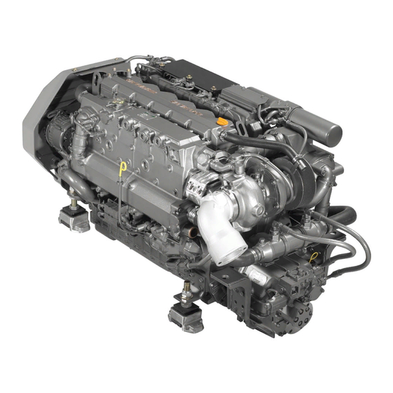
Page 18: 6Ly3-Etp Exterior Views
GENERAL SERVICE INFORMATION 6LY3-ETP Exterior Views 6LY3-ETP EXTERIOR VIEWS Operation Side Figure 3-1 0006254 Figure 3-1 Non-Operation Side Figure 3-2 (10) (17) (16) (11) (12) (13) (14) 0006255 (15) Figure 3-2 6LY3 Service Manual © 2007 Yanmar Marine International... - Page 19 13 – Seawater Pump 5 – Oil Filter 14 – Alternator 6 – Intercooler 15 – V-Belt 7 – Flywheel 16 – Fuel Filter 8 – Air Silencer 17 – Coolant Pump 9 – Turbocharger 6LY3 Service Manual © 2007 Yanmar Marine International...
-
Page 20: Diesel Fuel
• BS 2869-A1 or A2 for UK Kerosene, residual fuel or Biocide produces poor fuel quality and will result in reduced engine • JIS K2204-2 for JAPAN performance and excessive wear of internal components. 6LY3 Service Manual © 2007 Yanmar Marine International... - Page 21 6 – Approximately 500 mm (20 in.) 7 – Fuel / Water Separator 0006257 8 – Diesel Fuel Priming Pump 9 – Less than 500 mm (20 in.) Figure 3-3 10 – To Diesel Fuel Injection Pump 6LY3 Service Manual © 2007 Yanmar Marine International...
-
Page 22: Engine Oil
If the engine is operated at temperatures below 1. Check that the engine oil, oil storage container those shown in Figure 3-5, consult your Yanmar and filling equipment are free of sediment and Marine dealer for special lubricants and starting water. -
Page 23: Engine Coolant
• SAE J814C, J1941, J1034, J2036 temperature range in which you will be operating. • ASTM D3306 • ASTM D4985 Yanmar recommends using genuine Yanmar coolant / antifreeze. Contact your authorized Yanmar dealer or distributor. Recommended Engine Coolants: • TEXACO LONG LIFE COOLANT ANTIFREEZE, both standard and pre-mixed. -
Page 24: Engine Outline Drawings
GENERAL SERVICE INFORMATION Engine Outline Drawings ENGINE OUTLINE DRAWINGS 6LY3-ETP / STP / UTP (YT-15 MOUNT) Figure 3-6 Figure 3-6 6LY3 Service Manual 3-10 © 2007 Yanmar Marine International... -
Page 25: 6Ly3-Etp
Engine Outline Drawings GENERAL SERVICE INFORMATION 12/05 6LY3-ETP Figure 3-7 Figure 3-7 6LY3 Service Manual 3-11 © 2007 Yanmar Marine International... -
Page 26: Exhaust Gas Emission Regulations
Exhaust Gas Emission Regulations EXHAUST GAS EMISSION REGULATIONS 6LY3 series engines are applicable with Marine Compression Ignition Engines Regulation of the EPA (40 CFR Part 94) in the U.S. RCD Regulation and BSO Regulation in Europe and other regulations are applied to this engine. -
Page 27: Epa Exhaust Gas Emission Standard
1. Fuel: The diesel fuel ASTM D975 No. 1-D or No. 2-D, equivalent (Cetane No. 3.45 minimum). 2. Oil: API grade, class CD. 6LY3 Service Manual 3-13 © 2007 Yanmar Marine International... -
Page 28: Engine Nameplate
Continuous power kW Speed of prop,shaf t Fuel stop power kW ENG.No. 119175-7202 0006420 Figure 3-10 REDUCTION AND REVERSING GEAR Refer to your Marine Gear Service Manual for inspection, disassembly and reassembly information. 6LY3 Service Manual 3-14 © 2007 Yanmar Marine International... -
Page 29: Principal Engine Specifications
5. The “Total Engine Oil Capacity” includes the oil in the oil pan, channels, coolers and filter. 6. The “Effective Engine Oil Capacity” indicates the difference in maximum scale of the dipstick and minimum scale. 6LY3 Service Manual 3-15 © 2007 Yanmar Marine International... -
Page 30: Abbreviations And Symbols
Hg Ω inch pound** in.-lb joule μ micro Japanese Automobile Standards percent JASO Organization * Work torque such as engine torque kelvin ** Work torque such as starter motor torque kilogram 6LY3 Service Manual 3-16 © 2007 Yanmar Marine International... -
Page 31: Unit Conversions
4.4480 0.4536 = kgf Units of Temperature 0.2248 = lbf 0.1020 = kgf °F = (1.8 x °C) + 32 2.2050 = lbf °C = 0.556 x (°F - 32) 9.8070 6LY3 Service Manual 3-17 © 2007 Yanmar Marine International... - Page 32 GENERAL SERVICE INFORMATION Unit Conversions This Page Intentionally Left Blank 6LY3 Service Manual 3-18 © 2007 Yanmar Marine International...
- Page 33 Safety Precautions ................4-3 Introduction..................4-3 The Importance of Periodic Maintenance........4-3 Performing Periodic Maintenance ..........4-3 Yanmar Replacement Parts ............4-3 Required EPA Maintenance ............4-3 EPA Requirements................4-3 Inspection and Maintenance............4-3 Inspection and Maintenance of EPA Emission-Related Parts... 4-5 Periodic Maintenance Procedures ..........
-
Page 34: 6Ly3 Service Manual
PERIODIC MAINTENANCE This Page Intentionally Left Blank 6LY3 Service Manual © 2007 Yanmar Marine International... -
Page 35: Safety Precautions
Safety Precautions PERIODIC MAINTENANCE 12/05 SAFETY PRECAUTIONS Yanmar Replacement Parts Yanmar recommends that using genuine Yanmar Before servicing the 6LY3 marine engines, review parts when replacement parts are needed. the Safety Section on page 2-1. Genuine replacement parts help ensure long engine life. -
Page 36: Periodic Maintenance Schedule
The following should be treated only as a general guideline. : Check : Replace : Contact your authorized Yanmar Marine dealer or distributor Every 50 Every 250 Every 500... -
Page 37: Inspection And Maintenance Of Epa Emission-Related Parts
Periodic Maintenance Schedule PERIODIC MAINTENANCE 12/05 : Check : Replace : Contact your authorized Yanmar Marine dealer or distributor Every 50 Every 250 Every 500 Every 1000 Every 2000 Before Hours or System Item Hours or Hours or Hours or... -
Page 38: Periodic Maintenance Procedures
2. If oil level is low, fill to the specified level through the filler port. NOTICE: Avoid overfilling the engine oil. Add oil to the upper limit line on the dipstick. Overfilling may induce oil into the combustion chamber and damage components. 6LY3 Service Manual © 2007 Yanmar Marine International... - Page 39 Figure 4-3 0006160 Figure 4-3 1 – Coolant Recovery Tank Cap 2 – LOW Mark 3 – FULL Mark 4 – Coolant Recovery Tank 6LY3 Service Manual © 2007 Yanmar Marine International...
-
Page 40: After Initial 50 Hours Of Operation
Yanmar dealer or distributor. Lube oil filter (bypass) Filter bracket 007088-00E 0006161 Figure 4-4 1 – Oil Filler Cap 2 – Bypass Filter 3 – Oil Filter Mounts 4 – Full Flow Filter 6LY3 Service Manual © 2007 Yanmar Marine International... - Page 41 2. Check the wiring harness and connectors to the control cable line for the marine gear. Check for loose wiring. Check that the shifting of the marine gear moves smoothly and test it in the NEUTRAL, FORWARD and REVERSE positions. 6LY3 Service Manual © 2007 Yanmar Marine International...
-
Page 42: Every 50 Hours Of Operation
5. After reassembly of the fuel / water separator, be sure to bleed air from the fuel system. 6LY3 Service Manual 4-10 © 2007 Yanmar Marine International... - Page 43 Figure 4-7 1 – Terminal 2 – Cap 3 – Cover 4 – Cathode Plate 5 – Separator 6 – Glass Mat 7 – Zinc Anode Plate 8 – Battery Case 6LY3 Service Manual 4-11 © 2007 Yanmar Marine International...
- Page 44 Converted specific gravity at 20 C 001348-01E Testing Battery Charge • Use a battery tester (Figure 4-9, (1)) or hydrometer to check battery condition. If the battery is discharged, recharge it. 6LY3 Service Manual 4-12 © 2007 Yanmar Marine International...
- Page 45 Figure 4-12 3. Battery Appearance • Replace the battery if cracked or deformed. • Clean with fresh water if contaminated. Figure 4-10 0006169 Figure 4-12 0006167 Figure 4-10 1 – Float 6LY3 Service Manual 4-13 © 2007 Yanmar Marine International...
- Page 46 Replace the belt if it is damaged. 1 – Freshwater Pump 2 – Adjuster 3 – Adjuster Bolt 4 – Alternator 5 – Deflection 8-10 mm (Approximately 3/8 in.) 6 – V-Belt 6LY3 Service Manual 4-14 © 2007 Yanmar Marine International...
-
Page 47: Every 250 Hours Of Operation
Be sure to check the following items every modifications or repairs should be performed by 250 hours or after one year of operation, whichever your authorized YANMAR service center. comes first. WARNING! • Check the Fuel Injector Spray Pattern (Initial •... - Page 48 5 – Adjusting Shim 13 – No. 1 Pressure Spring 6 – Tip Packing 14 – Adjusting Shim 7 – Straight Pins 15 – Nozzle Holder Body 8 – No. 2 Pressure Spring Seat 6LY3 Service Manual 4-16 © 2007 Yanmar Marine International...
- Page 49 NOTICE: Only No. 1 opening equipment are required. Consult your authorized pressure can be measured with this method. YANMAR marine dealer or distributor. Specialized equipment is required to (a) Install the fuel injection nozzle to the nozzle measure No. 2 opening pressures precisely.
- Page 50 CAUTION! Never use a steel wire brush to clean fuel injectors. Damage to the nozzle and other components is likely to result. 0006177 Figure 4-20 1 – Flywheel Housing 2 – Index Mark 6LY3 Service Manual 4-18 © 2007 Yanmar Marine International...
- Page 51 Tighten the rocker arm 120° each time. NOTICE: Firing Order is adjusting bolt lightly (temporarily). 1-4-2-6-3-5. Standard Valve Clearance 0.15-0.25 mm Intake valve (0.0059-0.0098 in.) 0.45-0.55 mm Exhaust valve (0.0177-0.0216 in.) 6LY3 Service Manual 4-19 © 2007 Yanmar Marine International...
- Page 52 (Figure 4-24, (3)). 0.15-0.25 mm Intake Valve 3. Replace the element, reinstall the bolt and (0.0059-0.0098 in.) tighten. 0.45-0.55 mm Exhaust Valve (0.0177-0.0216 in.) 4. Bleed air from the fuel filter system. 6LY3 Service Manual 4-20 © 2007 Yanmar Marine International...
- Page 53 1 – Cover 2 – Gasket 3 – Filter Element 4 – Gasket 5 – Spring 6 – Case 7 – Gasket 8 – Drain Plug 9 – Gasket 10 – Center Bolt 6LY3 Service Manual 4-21 © 2007 Yanmar Marine International...
- Page 54 1 – Zinc Anode washer) from the intercooler. 2 – Zinc Anode Plug 3 – Identification Label Figure 4-26 0006185 Figure 4-26 1 – Zinc Anode Location 2 – Heat Exchanger 6LY3 Service Manual 4-22 © 2007 Yanmar Marine International...
- Page 55 2. Crankshaft pulley bolts 3. Fuel injection nozzle set bolts 4. Fuel injection pipe joint nut 5. Rod bolts 6. Flywheel retainer bolts 7. Bearing cap bolts 6LY3 Service Manual 4-23 © 2007 Yanmar Marine International...
- Page 56 3 – Coolant Tank 4 – Notches 5. Pour coolant slowly into the coolant tank so that air bubbles do not develop. Pour until the coolant overflows from the filler port. 6LY3 Service Manual 4-24 © 2007 Yanmar Marine International...
-
Page 57: Every 500 Hours Of Operation
Inspect the Thermostat See Inspecting the Thermostat on page 7-18. Replace the Exhaust / Water Mixing Elbow Replace the used mixing elbow with a new one, even if no damage is found. 6LY3 Service Manual 4-25 © 2007 Yanmar Marine International... - Page 58 HOT KEY Mode, as a dedicated hot key is not required to view these screens. Use can hold Right most key down go into the menu mode and then via this menu access the desired screen. 0006196 Figure 4-33 6LY3 Service Manual 4-26 © 2007 Yanmar Marine International...
- Page 59 NOTICE: The high idle speed is fixed and cannot increments from 700 rpm to 800 rpm. Adjust the be changed. low idle speed by using “+” or “-” button. Push the SET button and a beep will sound. 6LY3 Service Manual 4-27 © 2007 Yanmar Marine International...
-
Page 60: Every 1000 Hours Of Operation
2. If trash, scale or rust is found in heat exchangers, clean them. (See Inspect the heat exchanger and pressure cap. See Heat Exchanger Components and Functions on page 7-13. on page 4-30.) 6LY3 Service Manual 4-28 © 2007 Yanmar Marine International... -
Page 61: Every 2000 Hours Of Operation
0006191 Figure 4-35 1 – Air Inlet Pressure 2 – Container Filled w / Light Oil 3 – Blocked 4 – Tappet 5 – Measuring Cylinder 6LY3 Service Manual 4-29 © 2007 Yanmar Marine International... - Page 62 (whichever comes first). This lowers cooling performance, so it is necessary to clean and maintain the oil cooler. See your authorized Yanmar marine dealer or distributor to replace the rubber fuel hoses. Internal contamination of the oil cooler reduces...
-
Page 63: Testing Engine Operation
(See Adjusting the No-load Minimum 2. Fill the diesel fuel, oil and coolant. Speed on page 4-26.) 3. Only use oil recommended by Yanmar. 4. Perform loaded operations as required. 4. Be sure to mix LLC with fresh water. - Page 64 Close the seacock and fuel cocks. Check the engine installation Stopping the bolts. Engine When the temperature is expected to fall below freezing, drain the seawater. Drain the seawater pump. Turn off the battery switch. 6LY3 Service Manual 4-32 © 2007 Yanmar Marine International...
-
Page 65: Long-Term Storage
6. Cover the silencer and electric parts with a (d) Operate the engine at idle speed for about waterproof cover to prevent water and dirt from 5 minutes. Repeat monthly, if possible. entering. 6LY3 Service Manual 4-33 © 2007 Yanmar Marine International... - Page 66 PERIODIC MAINTENANCE Periodic Maintenance Procedures This Page Intentionally Left Blank 6LY3 Service Manual 4-34 © 2007 Yanmar Marine International...
- Page 67 Removing the Drive Shaft Housing Cover....... 5-21 Removing the Flywheel and Flywheel Housing....... 5-21 Turning the Engine Block Over..........5-21 Removing the Oil Pan and Spacer .......... 5-21 Removing the Connection Rod End Caps....... 5-21 6LY3 Service Manual © 2007 Yanmar Marine International...
- Page 68 Installing the Oil Pressure Regulating Valve ......5-63 Installing the Coolant Passage Cover ........5-63 Installing the Fuel Injection Pump ........... 5-63 Installing the Flywheel ............. 5-63 Installing the Cylinder Head Assembly........5-64 Installing the Intercooler ............5-65 6LY3 Service Manual © 2007 Yanmar Marine International...
- Page 69 Installing the Engine Turbocharger.......... 5-74 Installing the Mixing Elbow ............5-75 Installing the Oil Lines for the Fuel Injection Pump ....5-76 Installing the Alternator............5-76 Installing the Starter Motor ............5-76 6LY3 Service Manual © 2007 Yanmar Marine International...
- Page 70 ENGINE This Page Intentionally Left Blank 6LY3 Service Manual © 2007 Yanmar Marine International...
-
Page 71: Safety Precautions
All internal combustion engines create carbon monoxide gas during operation and special precautions are required to avoid carbon monoxide poisoning. 6LY3 Service Manual © 2007 Yanmar Marine International... -
Page 72: Disassembling The Engine And Components
• Clean parts with an approved cleaner in a suitable location. • Clear an adequate area for parts and prepare a container. • Drain coolant, seawater and oil. • Close the seacock. 6LY3 Service Manual © 2007 Yanmar Marine International... -
Page 73: Special Tools
10 x 13 Wrench 12 x 14 17 x 19 22 x 24 0005719 Screwdriver — 0005720 Steel Hammer Local 0005721 Copper Hammer Local 0005722 Mallet Local 0005723 Nippers Local 0005724 Pliers Local 0005725 6LY3 Service Manual © 2007 Yanmar Marine International... - Page 74 Local (1 set) 0005727 Scraper Local 0005728 Lead Rod Local 0005729 File Local (1 set) 0005730 Local Rod Spanner for Size: Hexagon Socket Head 6 mm Bolts 8 mm 10 mm 0005731 6LY3 Service Manual © 2007 Yanmar Marine International...
-
Page 75: Special Hand Tools
86 mm 24 mm -0.48 mm) 10° ± 30° (Extraction) (1.574 in.) (3.385 in.) (0.944 in.) (1.456 in.) (0.228 in. 0005736 (-0.007 in. (-0.017 in. ± 0.019 in. -0.019 in.) -0.018 in.) 6LY3 Service Manual © 2007 Yanmar Marine International... - Page 76 Piston Ring — Compressor 0005740 Piston Ring Tool (For removal / — insertion of the piston ring.) 0005741 Valve Lapping Tool — (Rubber Cap Type) 0005742 Valve Lapping — Powder 0005743 6LY3 Service Manual 5-10 © 2007 Yanmar Marine International...
- Page 77 9.5 mm 65 mm 4 mm Exhaust (0.637 in.) (0.866 in.) (0.531 in.) (0.374 in.) (2.559 in.) (0.157 in.) Stem Seal Insertion Tool — (For inserting the 0005748 stem seal.) 0005749 6LY3 Service Manual 5-11 © 2007 Yanmar Marine International...
-
Page 78: Measuring Instruments
50-100 mm (1.968-4 in.) 0005752 Thickness Gauge 0.05-2 mm (0.001-0.078 in.) 0005753 0-343 N·m Torque Wrench (0-35 kgf·m) (0-252 lb-ft) 0005754 0-49 MPa Nozzle Tester (0-500 kgf / cm (0-7106 psi) 0005755 6LY3 Service Manual 5-12 © 2007 Yanmar Marine International... - Page 79 0006347 Depth Micrometer Measures the valve sink. 0005759 Measures the distortion in the position of the Square springs and squareness of parts. 0005760 V-Block Used in measuring shaft distortions. 0005761 6LY3 Service Manual 5-13 © 2007 Yanmar Marine International...
- Page 80 Checks the shape and pressure of spray Nozzle Tester emitted from the fuel injection valve at the time of injection. 0006343 Digital Thermostat Measures the temperature of various parts. DIGITAL Float 0005765 6LY3 Service Manual 5-14 © 2007 Yanmar Marine International...
- Page 81 Pipe Clamp Type exterior of the revolving shaft. 0005768 Circuit Tester Measures the resistance, voltage and Volt Ohm Meter (VOM) continuity of the electric circuit. 0005769 6LY3 Service Manual 5-15 © 2007 Yanmar Marine International...
- Page 82 • The cleaning agent removes substances, such as carbon, adhering to disassembled parts. Cleaning Agent — • If a cleaning machine is used, prepare 4 to 6% mixture of 60° to 80° to ensure more effective cleaning. 6LY3 Service Manual 5-16 © 2007 Yanmar Marine International...
- Page 83 4. When gaskets are used, do not use sealant ® Three Bond TB1212. 0005770 Figure 5-1 1 – Oil Pan Mating Surface 2 – Inside of Oil Pan ® 3 – Bead of Three Bond TB1212 4 – Outside 6LY3 Service Manual 5-17 © 2007 Yanmar Marine International...
-
Page 84: Removing The Engine From The Vessel
NOTICE: If an oil supply / discharge pump is used, install the hose in the dipstick guide. Removing the Electrical Wiring Remove the wiring from the engine. 6LY3 Service Manual 5-18 © 2007 Yanmar Marine International... -
Page 85: Removing The Fuel Filter And Fuel Hoses
1 – Intake Air Hose 1 – Oil Cooler 2 – Air Silencer 2 – Oil Filter 3 – Breather Hose 3 – Intercooler 4 – Mixing Elbow 5 – Turbocharger 6LY3 Service Manual 5-19 © 2007 Yanmar Marine International... -
Page 86: Removing The Starter Motor
Removing the Fuel Injection Lines 1. Remove the fuel injection hose retainer. 2. Loosen the cap nuts on both ends of the fuel injection hose and remove the fuel injection hose. 6LY3 Service Manual 5-20 © 2007 Yanmar Marine International... -
Page 87: Removing The Fuel Injection Nozzles
Remove the connecting rod and piston assembly. Removing the Drive Shaft Housing Cover Loosen the drive shaft housing cover bolts and remove the drive shaft housing cover from the drive shaft housing. 6LY3 Service Manual 5-21 © 2007 Yanmar Marine International... -
Page 88: Inspecting The Cylinder Block And Components
5 – 35 mm (1.377 in.) Plug 6 – Flywheel End 7 – 40 mm (1.574 in.) Plug 8 – 16 mm (0.629 in.) Plug 9 – 40 mm (1.574 in.) Plug 6LY3 Service Manual 5-22 © 2007 Yanmar Marine International... -
Page 89: Replacing Freeze Plugs
(Drive the plug straight into • Hammer the opening.) 0005591 1 – Jig Do not add coolant to the cylinder block — for two hours after the plugs are set. 0005592 6LY3 Service Manual 5-23 © 2007 Yanmar Marine International... -
Page 90: Fabricating A Freeze Plug Driver
• Measure at 20 mm (0.787 in.) (Figure 5-13, (3)) from the bottom of the piston skirt in directions 4 and 5 as shown in Figure 5-13. 0005594 NOTICE: Direction 4 is the crankshaft center line. Figure 5-12 6LY3 Service Manual 5-24 © 2007 Yanmar Marine International... - Page 91 This produces six different measurement values. Calculate the average value of all the measurements for each cylinder bore and compare with the wear limits. See Measuring Cylinder Bore Diameters on page 5-25. 6LY3 Service Manual 5-25 © 2007 Yanmar Marine International...
-
Page 92: Cylinder Head Components And Functions
The areas between the intake / exhaust valves are cooled with internal circulating water. Figure 5-14 (8) (9) (13) (10) (14) (15) (16) (17) (12) (11) (18) (22) (19) (21) (20) 0005596 Figure 5-14 6LY3 Service Manual 5-26 © 2007 Yanmar Marine International... - Page 93 8 – Rocker Arm Spring 20 – Intake Valve 9 – Intake Rocker Arm 21 – Exhaust Valve 10 – Bridge Seat 22 – Cylinder Head 11 – Rocker Arm Support 6LY3 Service Manual 5-27 © 2007 Yanmar Marine International...
-
Page 94: Inspecting The Cylinder Head
• Remove the fuel injection nozzle, intake and exhaust valve. • Check for discoloration or distortion. • Perform a dye penetrent inspection to check for any cracks. 0005599 Figure 5-17 6LY3 Service Manual 5-28 © 2007 Yanmar Marine International... - Page 95 Figure 5-20 NOTICE: When seat adjustment is necessary, check the valve and valve guide. If the clearance exceeds the tolerance, replace the valve or the valve guide and grind the seat. 6LY3 Service Manual 5-29 © 2007 Yanmar Marine International...
- Page 96 Exhaust Valve Stem Outside Diameter Standard Limit 7.955-7.970 mm 7.90 mm (0.3131-0.3137 in.) (0.311 in.) Figure 5-22 55mm 55mm (2.165 in.) (2.165 in.) 0005603 0005602 Figure 5-22 Figure 5-21 Figure 5-23 0005604 Figure 5-23 6LY3 Service Manual 5-30 © 2007 Yanmar Marine International...
- Page 97 Figure 5-24 0005605 Figure 5-24 1 – Cylinder Head 2 – Valve Sink 0005606 Figure 5-25 1 – Insertion Tool 2 – Tap Valve Guide 3 – Cylinder Head 4 – Tool 6LY3 Service Manual 5-31 © 2007 Yanmar Marine International...
- Page 98 4. Use the valve stem seal installer tool to install the seal. Tap the seal in position using a tool stop (Figure 5-27, (6)) to prevent damage to the valve stem seal. 6LY3 Service Manual 5-32 © 2007 Yanmar Marine International...
- Page 99 1 mm (0.039 in.) 1 – Top K2 = 22.9 N / mm Compression 2 – Small Pitch Side (Yellow) (2.33 kgf / mm) — 3 – Down Side (82.3 ozf / 0.399 in.) 6LY3 Service Manual 5-33 © 2007 Yanmar Marine International...
- Page 100 (43 ± 3.6 lb-ft) Part Name Part No. Nozzle Sleeve 119578-11820 O-Ring (1AP22A) 24311-350220 Nozzle Sleeve Gasket 119578-11960 0005614 Figure 5-32 1 – O-Ring 2 – Nozzle Sleeve 3 – M13 4 – Gasket 6LY3 Service Manual 5-34 © 2007 Yanmar Marine International...
- Page 101 0005618 Piston Top Clearance Figure 5-35 0.78-0.98 mm (0.031-0.039 in.) 1 – Exhaust Rocker Arm 2 – Intake Rocker Arm 3 – Rocker Arm Support 4 – Rocker Arm Shaft Assembly 6LY3 Service Manual 5-35 © 2007 Yanmar Marine International...
-
Page 102: Inspecting The Pistons And Piston Pins
4. Inspect the contact surface of the adjusting bolt and push rod. Replace it if there is abnormal wear or flaking. 6LY3 Service Manual 5-36 © 2007 Yanmar Marine International... - Page 103 +0.020 minimum Cylinder Liner Inside below +0.020 Diameter, +0.010 minimum below +0.010 0 minimum Cylinder Liner Inside Diameter, D1 Piston Outside Diameter, D2 105.900 mm (4.1692 in.) 105.794 mm (4.1651 in.) 6LY3 Service Manual 5-37 © 2007 Yanmar Marine International...
- Page 104 • Measure the thickness and width of the rings. Figure 5-40 • Measure the ring-to-groove clearance after installing the ring on the piston. • Replace if wear exceeds stated limits. 0005623 Figure 5-40 6LY3 Service Manual 5-38 © 2007 Yanmar Marine International...
- Page 105 • Thoroughly clean the ring grooves when replacing piston rings (Figure 5-44, (3)). • The side with the manufacturer's mark (Figure 5-45, (1)) must face up. Figure 5-45 0005628 Figure 5-45 6LY3 Service Manual 5-39 © 2007 Yanmar Marine International...
- Page 106 3 – Oil Control Ring 4 – Top Compression Ring Gap 5 – Oil Control Ring Gap 6 – Middle Compression Ring Gap 7 – Direction of Piston Pin 8 – Direction of Side Pressure 6LY3 Service Manual 5-40 © 2007 Yanmar Marine International...
-
Page 107: Inspecting The Connecting Rods
• Insert the appropriate mandrel (Figure 5-49, (3)) into both ends of the connecting rod. 0005634 Figure 5-50 1 – Connecting Rod Tool 2 – Twist Measurement Using a Rod Alignment Tool 6LY3 Service Manual 5-41 © 2007 Yanmar Marine International... - Page 108 Thickness (0.0782-0.0787 in.) 0.036-0.093 mm 0.160 mm Clearance (0.0014-0.0036 in.) (0.0062 in.) An alternate procedure for measuring crank pin oil clearance is to use a plastic gauge. 6LY3 Service Manual 5-42 © 2007 Yanmar Marine International...
- Page 109 • Make sure the crankshaft is not scratched. • Remove the connecting rod and measure the plastic gauge with measuring paper. • Clean and clear all oil holes. 6LY3 Service Manual 5-43 © 2007 Yanmar Marine International...
-
Page 110: Inspecting The Crankshaft
5 – Main Bearing (Intermediate) Figure 5-55 6 – Main Bearing Cap (Intermediate) 1 – Cylinder Gauge 7 – Main Bearing Bolt 8 – Main Bearing Cap (Basic) 9 – Thrust Bearing (Flywheel End) 6LY3 Service Manual 5-44 © 2007 Yanmar Marine International... - Page 111 2 – Bend 0005642 Figure 5-59 Figure 5-57 0005644 Figure 5-59 1 – Dial Indicator • Compare reading with specified limit. Crankshaft Bend Limit 1/2 the Dial Gauge Reading 0.03 mm (0.0011 in.) 6LY3 Service Manual 5-45 © 2007 Yanmar Marine International...
- Page 112 • Replace the thrust bearing if it is worn beyond the crank pin, measure the inside diameter of the stated limit. connecting rod crank pin bearing. Crankshaft Side Clearance Standard Limit 0.132-0.223 mm 0.29 mm (0.0051-0.0087 in.) (0.0114 in.) 6LY3 Service Manual 5-46 © 2007 Yanmar Marine International...
- Page 113 6 – Main Bearing Cap Bolt 4. The “FW” on the cap must face the flywheel end 7 – Main Bearing Cap of the engine. 5. Tighten the cap to the specified torque. 6LY3 Service Manual 5-47 © 2007 Yanmar Marine International...
-
Page 114: Inspecting The Camshaft And Tappets
Camshaft Side Clearance Standard Limit 0.05-0.20 mm 0.29 mm 0005651 (0.0019-0.0078 in.) (0.0114 in.) Figure 5-66 • Replace the cam if any lobes are worn beyond the stated limit. 6LY3 Service Manual 5-48 © 2007 Yanmar Marine International... - Page 115 (2.2433-2.2460 in.) (2.2452 in.) 56.910-59.940 mm 56.880 mm Camshaft OD (2.2405-2.3598 in.) (2.2393 in.) Camshaft Bend Limit 0.040-0.140 mm 0.250 mm 0.02 mm (0.0007 in.) Oil Clearance (0.0015-0.0055 in.) (0.0098 in.) 6LY3 Service Manual 5-49 © 2007 Yanmar Marine International...
-
Page 116: Inspecting The Tappets
• Check the contact area of each tappet. • Replace if excessively or unevenly worn. Figure 5-70 0005653 Figure 5-70 1 – Abnormal Contact Area 2 – Normal Contact Area 6LY3 Service Manual 5-50 © 2007 Yanmar Marine International... -
Page 117: Inspecting The Push Rods
1 – Idler Gear engine performance. 2 – Idler Gear Bearing 3 – Idler Gear Shaft Timing Gear Backlash Standard Limit 0.08-0.16 mm 0.25 mm (0.0031-0.0062 in.) (0.0098 in.) 6LY3 Service Manual 5-51 © 2007 Yanmar Marine International... -
Page 118: Indexing The Gear Timing Marks
Figure 5-74 1 – Fuel Injection Pump Gear 2 – Camshaft Gear 3 – Seawater Pump Gear 4 – Idler Gear 5 – Crankshaft Gear 6 – Oil Pump Gear 0005659 6LY3 Service Manual 5-52 © 2007 Yanmar Marine International... -
Page 119: Inspecting The Flywheel And Housing
95 mm 0005662 Fit Joint Diameter (+0.035, 0) Figure 5-76 (3.7401 in.) 387 mm 1 – Flywheel Housing Center Diameter (15.2361 in.) Ring Gear 2 – Matching Index Marks No. of Teeth 6LY3 Service Manual 5-53 © 2007 Yanmar Marine International... -
Page 120: Inspecting The Intake / Exhaust System
2. Repair cracks or other damage to welded parts. is no air leak. Replace parts if needed. NEVER operate an engine with the intake air 3. Inspect all gaskets and replace as necessary. silencer removed. 6LY3 Service Manual 5-54 © 2007 Yanmar Marine International... -
Page 121: Assembling The Engine And Components
(Figure 5-79, (1)). Place wooden blocks on the floor and set the cylinder block upside down (with the cylinder head mounting surface facing down). Keep the positioning pins clear of the wooden blocks. 6LY3 Service Manual 5-55 © 2007 Yanmar Marine International... -
Page 122: Installing The Piston Cooling Nozzles
Figure 5-81 bearing. 1 – Piston Cooling Nozzle Inner Diameter After Press-Fitting 57 + 0.05 / -0.02 mm (2.2440 + 0.0019 / -0.0007 in.) 6LY3 Service Manual 5-56 © 2007 Yanmar Marine International... -
Page 123: Installing The Crankshaft
(173 lb-ft) Figure 5-85 0005783 Figure 5-83 1 – Crank Journal 2 – Cylinder Block Figure 5-84 0005785 Figure 5-85 1 – Arrow Mark 2 – Bearing Caps 0005784 Figure 5-84 6LY3 Service Manual 5-57 © 2007 Yanmar Marine International... -
Page 124: Installing The Oil Pump
1 – Oil Pump 3. Measure the gear backlash between the oil pump and idler gear and compare to the value specified below: Gear Backlash 0.12 ± 0.04 mm (0.0047 ± 0.001) 6LY3 Service Manual 5-58 © 2007 Yanmar Marine International... -
Page 125: Installing The Drive Shaft Housing
4 – Embossed Connecting Rod Mark (Flywheel End) 0005790 2. Orient the connecting rod to each piston Figure 5-90 (Figure 5-91). NOTICE: Coat all parts with clean engine oil. 1 – Camshaft 6LY3 Service Manual 5-59 © 2007 Yanmar Marine International... -
Page 126: Installing The Oil Pan Spacer
M8 x 35 mm bolts and two M8 x 30 mm 5. Torque all bolts to the specified values. bolts. Torque bolts to the specified value. Figure 5-92 0005792 Figure 5-92 1 – Spacer 2 – Cylinder Block 6LY3 Service Manual 5-60 © 2007 Yanmar Marine International... -
Page 127: Installing The Oil Pan
( 2 ) ( 2 ) ( 2 ) ( 2 ) ( 2 ) 0005796 Figure 5-96 1 – M10 x 30 mm bolts 2 – M10 x 35 mm bolts 6LY3 Service Manual 5-61 © 2007 Yanmar Marine International... -
Page 128: Installing The Seawater Pump
6. Lubricate and secure the idler gear to its spindle with four M10 bolts. 7. Tighten bolts to the following specified torque value. 0005798 Figure 5-98 1 – Positioning Mark 2 – Spindle Shaft 3 – Oil Hole 6LY3 Service Manual 5-62 © 2007 Yanmar Marine International... -
Page 129: Installing The Oil Pressure Regulating Valve
1. Apply sealant bead to the coolant passage Figure 5-102 cover (Figure 5-101, (1)). Figure 5-101 0005801 Figure 5-101 1 – Coolant Passage Cover 2 – Cylinder Block 2. Secure with bolts. 6LY3 Service Manual 5-63 © 2007 Yanmar Marine International... -
Page 130: Installing The Cylinder Head Assembly
11. Repeat the tightening sequence and bring all the head bolts to the torque value given in the stage. NOTICE: Head identification No. is marked on the upper surface on the flywheel end. 6LY3 Service Manual 5-64 © 2007 Yanmar Marine International... -
Page 131: Installing The Intercooler
2. Apply silicone grease to the O-rings, fit two O-rings to both sides of the cooler core and fit the side covers to the cooler. 3. Fit the intercooler to the engine. 6LY3 Service Manual 5-65 © 2007 Yanmar Marine International... -
Page 132: Installing The Intake Manifold
5. Torque M8 bolts to the following specified arm cover. values. Rocker Arm Shaft Support Bolt Torque (M8) 26 ± 3 N·m (2.6 ± 0.3 kgf·m) (19.1 ± 2.2 lb-ft) 6LY3 Service Manual 5-66 © 2007 Yanmar Marine International... -
Page 133: Installing The Coolant Pump
(23 ± 1 kgf·m) (166.6 ± 7.3 lb-ft) (Figure 5-110, (4)). 3. Install the O-ring (Figure 5-110, (2)) on the coolant passage cover. 4. Install and tighten the bolts to the specified torque value. 6LY3 Service Manual 5-67 © 2007 Yanmar Marine International... -
Page 134: Installing The Fuel Injection Nozzles
4. Apply oil to the fuel nozzle retainer (Figure 5-114, (1)) and the fuel nozzle bolt (Figure 5-115). 0005814 Figure 5-113 1 – Caution Label 2 – Damper (Crankshaft) 3 – Damper (Fuel Injection Pump) 6LY3 Service Manual 5-68 © 2007 Yanmar Marine International... - Page 135 1 – 1.5 mm (0.059 in.) Gap (3.2 ± 0.2 kgf·m) 2 – 1 mm (0.039 in.) Gap (23.1 ± 1.4 lb-ft) 3 – Fuel Nozzle 4 – Retainer 5 – Intake Rocker Arm 6LY3 Service Manual 5-69 © 2007 Yanmar Marine International...
-
Page 136: Installing The Heat Exchanger
2 – Centering Hole 4. Fit the separator seal to both side covers (water pump end and flywheel end). See Figure 5-118. 5. Fit the side cover to the heat exchanger. 6LY3 Service Manual 5-70 © 2007 Yanmar Marine International... -
Page 137: Installing The Engine Oil Cooler
(Figure 5-122, (5)) of the side cover. 5. Install the end covers to the oil cooler. 6. Install the oil cooler to the engine. 7. Install the intercooler and the filter bracket to the engine. 6LY3 Service Manual 5-71 © 2007 Yanmar Marine International... -
Page 138: Installing The Engine Coolant Hoses
(Figure 5-126, (6)) and oil cooler (Figure 5-126, (1). 0005827 Figure 5-125 1 – Oil Cooler 2 – Hose Clamps 3 – Mixing Elbow 4 – Heat Exchanger 6LY3 Service Manual 5-72 © 2007 Yanmar Marine International... - Page 139 4 – Flow from the Seawater Pump 9 – Flow from the Marine Gear 5 – Flow to the Marine Gear 10 – Flow from the Intercooler to the Oil Cooler 6LY3 Service Manual 5-73 © 2007 Yanmar Marine International...
-
Page 140: Installing The Engine Air Ducts
3. Install the turbocharger (Figure 5-128, (1)) with its attached oil line and loosely install two M10 x 18 mm bolts through bracket “A” and into the turbocharger. 6LY3 Service Manual 5-74 © 2007 Yanmar Marine International... -
Page 141: Installing The Mixing Elbow
6. Assemble the components and tighten the hose bands to the following specified torque value. Hose Band Torque 3 ± 0.5 N·m (0.3 ± 0.05 kgf·m) (2.2 ± 0.3 lb-ft) 6LY3 Service Manual 5-75 © 2007 Yanmar Marine International... -
Page 142: Installing The Oil Lines For The Fuel Injection Pump
V-Belt on page 4-14 and tighten all the bolts to the specified values. Installing the Starter Motor 1. Install the starter motor to the flywheel housing. 2. Tighten the bolts to the specified torque value. 6LY3 Service Manual 5-76 © 2007 Yanmar Marine International... - Page 143 Engine Control System Diagram ..........6-36 Sensors and Actuators ............6-37 Injection Quantity Control Diagram.......... 6-38 Injection Timing Control Diagram ..........6-39 Timer Phase Detection ............6-40 ECU Control Data Management..........6-41 ECU Data Flow................ 6-43 6LY3 Service Manual © 2007 Yanmar Marine International...
-
Page 144: Fuel System
FUEL SYSTEM This Page Intentionally Left Blank 6LY3 Service Manual © 2007 Yanmar Marine International... -
Page 145: Safety Precautions
Never use a shop rag to catch the fuel. ALWAYS put an approved fuel container under the opening whenever removing any fuel system component (such as changing the fuel filter). Dispose of waste properly. Wipe up all spills immediately. 6LY3 Service Manual © 2007 Yanmar Marine International... -
Page 146: Introduction
FUEL SYSTEM Introduction INTRODUCTION This section of the Service Manual describes the procedures necessary to remove, install and adjust the injectors and their associated system components as used on the Yanmar 6LY3 engines. 6LY3 Service Manual © 2007 Yanmar Marine International... -
Page 147: Specifications
Cam Profile Type AL50DFP39 Fuel Delivery 7.6 cm / revolution (0.463 cu. in.) Feed Pump Delivery Pressure 0.23-0.37 MPa (2.3-3.8 kgf / cm ) (33.3-53.6 psi) Suction Head 1.0 m (39.369 in) 6LY3 Service Manual © 2007 Yanmar Marine International... -
Page 148: Fuel System Diagram
5 – Fuel Feed Pump 2 – Fuel Return Line 6 – Fuel Line from Tank 3 – Fuel Filter 7 – Fuel Injection Pump 4 – Fuel Line to Tank 8 – Fuel Injection Line 6LY3 Service Manual © 2007 Yanmar Marine International... -
Page 149: Fuel Injection Pump / Governor / Timer
6-8 for the location of the rack position amplifier. 0005664 Figure 6-2 1 – Fuel Injection Pump 2 – Electro-Hydraulic Timer 3 – Fuel Feed Pump 4 – Electronic Governor 6LY3 Service Manual © 2007 Yanmar Marine International... -
Page 150: Fuel Injection Pump Components
FUEL SYSTEM Fuel Injection Pump / Governor / Timer Fuel Injection Pump Components Figure 6-3 Figure 6-3 6LY3 Service Manual © 2007 Yanmar Marine International... - Page 151 8 – Fuel Feed Pump 4 – Rack Position Standard Surface 9 – Camshaft Key Position at FIC No. 1 Cylinder 5 – Overflow of Fuel Outlet 10 – Rack Position Sensor / Amplifier 6LY3 Service Manual © 2007 Yanmar Marine International...
-
Page 152: Governor Components And Functions
1 – Fuel Decrease 5 – Fuel Injection Pump 2 – Fuel Increase 6 – Governor 3 – Control Rack 7 – Rack Position Sensor 4 – Timer 8 – Governor Solenoid (Rack Actuator) 6LY3 Service Manual 6-10 © 2007 Yanmar Marine International... -
Page 153: Timer Components And Functions
Timer Components and Functions Figure 6-5 Timer Components The 6LY3 series engine utilizes an electro-hydraulic timer. The timer consists of a piston, a cylinder and a cam drive coupling. The piston has helical spline outside and straight spline inside, as illustrated in Figure 6-6. - Page 154 2 – Advance Oil Passage 7 – Advance Oil Chamber 3 – Retard Oil Passage 8 – Pump Camshaft 4 – Helical Spline 9 – Engine Oil Outlet 5 – Retard Oil Chamber 6LY3 Service Manual 6-12 © 2007 Yanmar Marine International...
- Page 155 1 – Timer Solenoid 5 – Damper Shaft 2 – Pump Drive Gear 6 – Drive Direction 3 – Cylinder 7 – Piston Movement 4 – Piston 8 – Rotating Cam and Piston 6LY3 Service Manual 6-13 © 2007 Yanmar Marine International...
-
Page 156: Removing The Fuel Injection Pump
3 – Damper 1 – Index Mark (Drive Shaft Housing Cover) 2 – Index Mark (V-Pulley) 3. Remove the fuel injection lines, supply lines and cap the ends to keep dirt out. 6LY3 Service Manual 6-14 © 2007 Yanmar Marine International... - Page 157 Figure 6-11 Figure 6-12 1 – Fuel Injection Pump Gear 2 – Idler Gear 3 – Adjusting Mark “B” 4 – Two Index Marks 0005675 Figure 6-12 1 – FIC Lock Hole 6LY3 Service Manual 6-15 © 2007 Yanmar Marine International...
- Page 158 NOTICE: Use caution to avoid damaging the electromagnetic valve when removing the fuel injection pump. Keep the timer piston covered to prevent dirt from settling on piston. 0005677 Figure 6-14 1 – M8 x 25 (10T) Bolts 6LY3 Service Manual 6-16 © 2007 Yanmar Marine International...
-
Page 159: Installing The Fuel Injection Pump
Figure 6-17. 0006199 Figure 6-16 1 – Pump Bracket “B” 2 – Pump Bracket “A” 3 – Drive Shaft Housing 4 – Pump Bottom Bracket 5 – Governor Bracket 6LY3 Service Manual 6-17 © 2007 Yanmar Marine International... - Page 160 0005680 timer housing. Figure 6-18 Figure 6-20 1 – M10 x 80 mm Bolts (4) 2 – Pump Bottom Bracket 0005682 Figure 6-20 ® 1 – Apply Three Bond 1207C 6LY3 Service Manual 6-18 © 2007 Yanmar Marine International...
- Page 161 Figure 6-23 0005986 1 – M8 x 25 Bolt Figure 6-21 2 – M10 x 25 Bolt 1 – M8 x 25 (10T) Bolt 2 – M8 x 60 Dummy Bolt 6LY3 Service Manual 6-19 © 2007 Yanmar Marine International...
- Page 162 1 – M8 x 25 (10T) Bolt 1 – M8 x 25 Bolt 2 – M10 x 25 Bolt 11. Remove the dummy bolts (Figure 6-26, (1)). Figure 6-26 0005684 Figure 6-26 1 – Dummy Bolts 6LY3 Service Manual 6-20 © 2007 Yanmar Marine International...
- Page 163 Final Torque (2.60 ± 0.31 kgf·m) 25.5 ± 3 N·m (18.8 ± 2.2 lb-ft) (2.60 ± 0.31 kgf·m) (18.8 ± 2.2 lb-ft) Figure 6-28 Figure 6-30 0005691 0005693 Figure 6-28 Figure 6-30 6LY3 Service Manual 6-21 © 2007 Yanmar Marine International...
- Page 164 1 – Fuel Injection Pump Gear 2 – Damper Shaft 3 – M10 Bolt 18. Remove the FIC lock bolt (Figure 6-33, (1)) and collar. Figure 6-33 0005675 Figure 6-33 1 – FIC Lock Bolt 6LY3 Service Manual 6-22 © 2007 Yanmar Marine International...
- Page 165 M8 x 85 mm 20.4 N·m (15.5 lb-ft) M8 x 120 mm 35.5 N·m (26.1 lb-ft) M8 x 30 mm 20.4 N·m (15.5 lb-ft) M8 x 65 mm 20.4 N·m (15.5 lb-ft) 6LY3 Service Manual 6-23 © 2007 Yanmar Marine International...
-
Page 166: Troubleshooting The Fuel Injection System
Fuel filter is clogged. Disassemble and clean, or replace the element. Air is entering fuel lines. Replace the packing repair pipe. Insufficient fuel delivery from the feed pump. Repair or replace. 6LY3 Service Manual 6-24 © 2007 Yanmar Marine International... - Page 167 Injection from nozzle is improper. Repair or replace. When exhaust Injection timing is too fast. Check the trouble code. smoke is white: Coolant mixed with the fuel. Inspect the fuel system. 6LY3 Service Manual 6-25 © 2007 Yanmar Marine International...
-
Page 168: Fuel Injection Nozzle Components And Functions
This engine uses double-spring nozzles manufactured by DENSO. NOTICE: NEVER disassemble the nozzle holder 0005699 retaining nut at a Yanmar workshop. Defer maintenance to an authorized FIE service shop, Figure 6-36 which can maintain the DENSO fuel nozzles. 1 – Nozzle Body Holder Fuel Injection Nozzle Functions 2 –... - Page 169 22.5-26.5 N·m (229-270 kgf·cm) (16.5-19.5 lb-ft) Fuel Return Pipe Joint M6 7.0-9.0 N·m (71-92 kgf·cm) (5.1-6.6 lb-ft) NOTICE: The fuel injection nozzle for 6LY3-ETP is different in volume from that for the 6LY3-STP / -UTP. 6LY3 Service Manual 6-27 © 2007 Yanmar Marine International...
-
Page 170: Fuel Feed Pump Components And Functions
The negative (-) pressure which develops in the piston chamber makes the suction valve open and fills the piston chamber with fuel. 6LY3 Service Manual 6-28 © 2007 Yanmar Marine International... -
Page 171: Fuel Feed Pump Components
14 – Discharge Valve 6 – Piston 15 – Discharge Valve Spring 7 – Piston Spring 16 – O-Ring 8 – O-Ring 17 – Plug 9 – Piston Spring Plug 18 – Inter-Spindle 6LY3 Service Manual 6-29 © 2007 Yanmar Marine International... -
Page 172: Fuel Feed Pump Specifications
Figure 6-38 abnormal wear of the tappets and camshaft. 1 – Measuring Cylinder 2 – Air Pressure 3 – Container Filled with Light Oil 4 – Blocked (Plugged) 5 – Tappet 6LY3 Service Manual 6-30 © 2007 Yanmar Marine International... -
Page 173: Testing The Fuel Feed Pump
0005704 Figure 6-40 1 – Valve “B” 2 – Pressure Gauge 3 – Valve “A” 0005703 4 – Feed Pump Figure 6-39 1 – From Fuel Tank 2 – Fuel Delivery 6LY3 Service Manual 6-31 © 2007 Yanmar Marine International... - Page 174 1 – Valve “B” 2 – Valve “A” Volume Pressure: 0.22-0.31 MPa (2.2-3.2 kg / cm (31.9-44.9 psi) rpm: 600 3. Replace the piston spring if it is defective. 6LY3 Service Manual 6-32 © 2007 Yanmar Marine International...
-
Page 175: Fuel Filter Components And Functions
5 – Drain Plug 6 – Flow to Fuel Pump 0005708 Figure 6-44 1 – M14 x 1.5 mm 2 – M14 x 1.5 mm 3 – M8 x 1.25 mm 6LY3 Service Manual 6-33 © 2007 Yanmar Marine International... -
Page 176: Inspecting The Fuel Filter
2 – Fuel Filter Assembly 3 – Gasket 4 – Cover 5 – Filter Case 6 – Drain Plug 7 – Center Bolt 8 – Filter Element 9 – Rubber Pad 6LY3 Service Manual 6-34 © 2007 Yanmar Marine International... -
Page 177: Electronic Control System
ELECTRONIC CONTROL SYSTEM The Electronic Control System (ECS) is used with the 6LY3 series engines. In order to function, the Engine Control Unit (ECU), the electronic governor and electro-hydraulic timer are interconnected to the fuel injection pump. The ECU controls the fuel injection quantity and injection timing electronically. -
Page 178: Engine Control System Diagram
Fuel injection pump Crank angle sensor Rack position sensor Camshaft speed sensor Fuel temperature sensor Fuel feed pump Electro-hydraulic timer Oil pump Fuel tank Oil sump Fuel filter 0005710 Figure 6-46 6LY3 Service Manual 6-36 © 2007 Yanmar Marine International... -
Page 179: Sensors And Actuators
(On intake manifold) Electronic governor Timer solenoid Rack position sensor (On hydraulic timer) Injection pump (On governor) Pump speed sensor Fuel temperature sensor (On governor) (On injection pump) 0005711 Figure 6-47 6LY3 Service Manual 6-37 © 2007 Yanmar Marine International... -
Page 180: Injection Quantity Control Diagram
Engine speed Rack position Crank speed Rack actuator governor cal. control cal. Rack position Rack position feedback calculation Idle 0005712 Speed Figure 6-48 6LY3 Service Manual 6-38 © 2007 Yanmar Marine International... -
Page 181: Injection Timing Control Diagram
Rack position Ridle Engine load Speed Crank speed cal. Timer solenoid (Advance) Timer phase Timer phase target cal. control cal. Timer solenoid (Retard) Timer phase cal. Cam speed 0005713 Figure 6-49 6LY3 Service Manual 6-39 © 2007 Yanmar Marine International... -
Page 182: Timer Phase Detection
Timer phase detection Pulsar gear Crank gear Cam gear 12 +1 pulse 12 pulse Top pulse Top pulse Top pulse Crank pulse pulse -360° 0° 360° Crank angle 0005714 Figure 6-50 6LY3 Service Manual 6-40 © 2007 Yanmar Marine International... -
Page 183: Ecu Control Data Management
In order to prevent the misuse or illegal operation of an engine’s control system, the control program and data are managed by a production system. In addition, Yanmar’s production data management system can provide the correct data for replacing an ECU and / or fuel injection pump when it is necessary. - Page 184 In the case of replacing a fuel injection pump, the ECU of the engine must be rewritten by the Pump Adjustment Data by using a YDT. The rewriting of the ECU control data is performed by Yanmar authorized personnel when replacement of an ECU or its components is necessary.
-
Page 185: Ecu Data Flow
Figure 6-53 ORDER of ECU DATA SERVER PRODUCTION for replacement in factory SYSTEM ENGINE MODEL SERIAL NUMBER PROGRAM / MAP PRODUCTION DATA ENG & PUMP ADJUSTMENT DATA 0005717 Figure 6-53 6LY3 Service Manual 6-43 © 2007 Yanmar Marine International... - Page 186 FUEL SYSTEM Electronic Control System This Page Intentionally Left Blank 6LY3 Service Manual 6-44 © 2007 Yanmar Marine International...
- Page 187 Inspecting the Thermostat ............7-18 Testing the Thermostat............7-18 Seacock Components and Functions (Optional)......7-19 Seacock Precautions.............. 7-19 Inspecting the Seacock ............7-19 Bilge Pump and Strainer Components and Functions (Optional).. 7-20 6LY3 Service Manual © 2007 Yanmar Marine International...
- Page 188 Bilge Pump Characteristics ............. 7-21 Bilge Pump Insulation.............. 7-21 Bilge Pump Durability .............. 7-21 Bilge Pump Vibration Proof ............. 7-21 Bilge Pump Precautions ............7-21 Installing the Bilge Pump............7-21 Troubleshooting the Bilge Pump ..........7-23 6LY3 Service Manual © 2007 Yanmar Marine International...
-
Page 189: Safety Precautions
Coolant Hazard Wear eye protection and rubber gloves when handling Long Life Coolant (LLC). If contact with the eyes or skin should occur, flush eyes and wash immediately with clean water. 6LY3 Service Manual © 2007 Yanmar Marine International... -
Page 190: Coolant System Components And Functions
The coolant pump body also serves as a discharge passageway (line) at the cylinder head outlet and is fitted with a thermostat. 6LY3 Service Manual © 2007 Yanmar Marine International... -
Page 191: Coolant System Components
10 – Seawater Inlet 4 – Full Flow Oil Filter 11 – Seawater Pump 5 – Intercooler 12 – Thermostat 6 – Marine Gear Oil Cooler 13 – Coolant Pump 7 – Mixing Elbow 6LY3 Service Manual © 2007 Yanmar Marine International... -
Page 192: Seawater Pump Components And Functions
Minimum 1500 hours Impeller Maximum 10% after (Figure 7-3, (13)). Flow Drop 1000 hours Water Lip Seal Minimum 1000 hours Wear Plate End Cover Minimum 1500 hours Other Parts Minimum 3000 hours 6LY3 Service Manual © 2007 Yanmar Marine International... -
Page 193: Inspecting The Seawater Pump
7. Lightly tap the pump shaft from the impeller side and remove the pump shaft, bearings and drive gear as a set. 8. Remove the lip seal and mechanical seal if necessary. 6LY3 Service Manual © 2007 Yanmar Marine International... -
Page 194: Assembling The Seawater Pump
8. Insert the impeller (Figure 7-6, (2)) into the pump body. See Figure 7-6, (1) for impeller rotation. Impeller threads are toward the cover. Figure 7-5 0006204 Figure 7-5 1 – Cover 6LY3 Service Manual © 2007 Yanmar Marine International... -
Page 195: Coolant Pump Components And Functions
13 m (46.2 ft) 0006206 Figure 7-7 1 – Mechanical Seal 2 – Impeller 3 – Seal 4 – Cover 5 – Casing 6 – Shaft Bearing 7 – Pulley Seat 6LY3 Service Manual © 2007 Yanmar Marine International... -
Page 196: Coolant System Components
6 – Coolant Pump Assembly 2 – Seal 7 – Gasket 3 – Hose Elbow 8 – Flange 4 – V-Belts 9 – O-Ring 5 – V-Pulley 10 – Cylinder Head 6LY3 Service Manual 7-10 © 2007 Yanmar Marine International... -
Page 197: Disassembling The Coolant Pump
Replace the pump as an assembly if there is excessive coolant leakage due to mechanical seal or impeller seal wear. Inspect Coolant Pump Inspect the coolant pump body and flange, and clean off scale and rust. Replace if corroded. 6LY3 Service Manual 7-11 © 2007 Yanmar Marine International... - Page 198 (Figure 7-10, (2)) between the impeller and the plate (pump body bracket) to measure the clearance between the two. Figure 7-10 0006209 Figure 7-10 1 – Straight Edge 2 – Thickness Gauge 6LY3 Service Manual 7-12 © 2007 Yanmar Marine International...
-
Page 199: Heat Exchanger Components And Functions
1. Remove the heat exchanger from the cylinder head. 2. Remove the forward and aft covers, O-rings, gaskets and cooler core. NOTICE: Replace the O-rings and gaskets with new ones whenever the coolant tube core is removed. 6LY3 Service Manual 7-13 © 2007 Yanmar Marine International... -
Page 200: Inspecting The Heat Exchanger
0.11 MPa (16 psi). This seals the coolant system. 6LY3 Service Manual 7-14 © 2007 Yanmar Marine International... -
Page 201: Inspecting The Pressure Cap
6LYA and L6LY2A. The drops immediately, inspect the cap and repair pressure value 1.1 is punched on the top of the cap or replace as necessary. for 6LY3 as shown in Figure 7-16. 6LY3 Service Manual 7-15 © 2007 Yanmar Marine International... -
Page 202: Coolant Recovery Tank Components And Functions
Check the overflow line and replace if it is bent or cracked. Clean out the pipe if it is clogged. 0006216 Figure 7-18 1 – Filler Cap 2 – Coolant Tank 3 – Subtank 6LY3 Service Manual 7-16 © 2007 Yanmar Marine International... -
Page 203: Thermostat Components And Functions
Thermostat Specifications Opening Temperature 69-73°C (156-163°F) Full Open Temperature 85°C (185°F) Valve Lift at Full Open 10 mm (0.393 in.) (10) (11) (12) (13) (14) (15) 0006217 Figure 7-19 6LY3 Service Manual 7-17 © 2007 Yanmar Marine International... -
Page 204: Inspecting The Thermostat
3. Replace the thermostat every year or 2000 hours of operation, whichever comes first. 6LY3 Service Manual 7-18 © 2007 Yanmar Marine International... -
Page 205: Seacock Components And Functions (Optional)
6 – Scoop Strainer 7 – Bolt Numerous holes are drilled into the water side of the seacock and a scoop strainer is installed to prevent debris from entering the system. 6LY3 Service Manual 7-19 © 2007 Yanmar Marine International... -
Page 206: Bilge Pump And Strainer Components And Functions (Optional)
8 – Battery 3 – White Connector 9 – White (-) Cable 4 – Green Connector 10 – Inlet 5 – Blue Connector 11 – Strainer 6 – Red Connector 12 – Outlet 6LY3 Service Manual 7-20 © 2007 Yanmar Marine International... -
Page 207: Bilge Pump Characteristics
Before reusing, clean the inside of the pump to extend the pump cables.) and prime it to ensure that it is wet. Check that the pump is discharging water correctly. 6LY3 Service Manual 7-21 © 2007 Yanmar Marine International... - Page 208 NOTICE: The bilge pump impeller should be 3. Secure the strainer so that it will not turn upside replaced by an authorized YANMAR service center. down or on its side. Use the supplied hose and avoid thin vinyl hose and hose that is not heat “Bolt Lock”...
-
Page 209: Troubleshooting The Bilge Pump
Check to see if the specific gravity of the battery fluid is greater than 1.25. Recharge or replace the battery. Faulty starter switch. Consult your local Yanmar Marine dealer. Faulty pump. Consult your local Yanmar Marine dealer. Pump turns, but does not draw up water. - Page 210 COOLANT SYSTEM Bilge Pump and Strainer Components and Functions (Optional) This Page Intentionally Left Blank 6LY3 Service Manual 7-24 © 2007 Yanmar Marine International...
- Page 211 Oil Cooler Components and Functions ......... 8-10 Inspecting the Oil Cooler ............8-10 Rotary Waste Oil Pump Components and Functions (Optional) ... 8-10 Rotary Waste Oil Pump Components........8-11 Inspecting the Waste Oil Pump ..........8-11 6LY3 Service Manual © 2007 Yanmar Marine International...
- Page 212 LUBRICATION This Page Intentionally Left Blank 6LY3 Service Manual © 2007 Yanmar Marine International...
-
Page 213: Safety Precautions
Consult the local authorities or reclamation facility. NEVER dispose of hazardous materials by dumping them into a sewer, on the ground or into ground water or waterways. 6LY3 Service Manual © 2007 Yanmar Marine International... -
Page 214: Lubrication Components And Functions
4 – Filter Assembly 11 – Oil Intake Filter 5 – Full Flow Oil Filter 12 – Oil Pump 6 – Turbocharger 13 – Safety Valve 7 – Rocker Arm Shaft 14 – Heat Exchanger 6LY3 Service Manual © 2007 Yanmar Marine International... -
Page 215: Oil Pump Components And Functions
66.203 mm (2.606 in.) 0006222 Figure 8-2 1 – Cylinder Block 2 – Idler Gear 3 – Shims 4 – Oil Pump 5 – Intake Filter 6 – Oil Pressure Regulating Valve 6LY3 Service Manual © 2007 Yanmar Marine International... -
Page 216: Oil Pump Components
3 – Shaft 10 – Safety Valve Case 4 – Gear 11 – Seat 5 – Case 12 – Spring Pin 6 – Drive Gear 13 – Spring 7 – Shaft 14 – Ball 6LY3 Service Manual © 2007 Yanmar Marine International... -
Page 217: Removing The Oil Pump
1 – Feeler Gauge 8. Install all drain plugs. 4. Measure the oil pump gear-to-pump cover 9. Fill with the recommended engine oil to the clearance with straight edge and gauge upper level. (Figure 8-5). 6LY3 Service Manual © 2007 Yanmar Marine International... -
Page 218: Oil Pressure Control Valve Components And Functions
1 – Oil Pressure Control Valve Thickness of Adjustment Shim 2 – Bracket 0.2, 0.5, 1.0 mm 3 – Valve (0.008, 0.02, 0.04 in.) 4 – Spring 5 – Shim 6 – Seal 7 – Plug 6LY3 Service Manual © 2007 Yanmar Marine International... -
Page 219: Oil Filter Components And Functions
6 – Caution Label Replacing the Oil Filter 7 – Element Seal See Removing the Oil Filter and Oil Cooler on page 5-20 and Installing the Engine Oil Filters on page 5-71. 6LY3 Service Manual © 2007 Yanmar Marine International... -
Page 220: Oil Cooler Components And Functions
Repair or replace the cooler if there are any leaks. Oil Cooler Test Pressure Oil Circuit 0.8 MPa (116 psi) Seawater Path 0.3 MPa (44 psi) 6LY3 Service Manual 8-10 © 2007 Yanmar Marine International... -
Page 221: Rotary Waste Oil Pump Components
0006232 Figure 8-11 1 – Body 2 – Cover 3 – Oil Seal 4 – Shaft 5 – Spring 6 – Spindle 7 – Vane 8 – Cover 6LY3 Service Manual 8-11 © 2007 Yanmar Marine International... - Page 222 LUBRICATION Rotary Waste Oil Pump Components and Functions (Optional) This Page Intentionally Left Blank 6LY3 Service Manual 8-12 © 2007 Yanmar Marine International...
- Page 223 Cleaning the Turbocharger............9-15 Inspecting the Turbocharger Components ......9-16 Assembling the Turbocharger ............9-19 Installing the Floating Bearings ..........9-19 Installing the Turbine Rotor Shaft ..........9-20 Installing the Thrust Bearing............ 9-20 6LY3 Service Manual © 2007 Yanmar Marine International...
- Page 224 Troubleshooting the Turbocharger ..........9-23 Black Smoke ................9-23 White Smoke ................9-24 Excessive Oil Consumption............. 9-24 Reduced Engine Power............9-24 Poor Follow-Up of the Turbocharger ........9-24 Unusual Sound or Vibration ............ 9-25 6LY3 Service Manual © 2007 Yanmar Marine International...
-
Page 225: Safety Precautions
SAFETY PRECAUTIONS INTRODUCTION Before servicing the engine turbocharger, review This section of the Service Manual describes the the Safety Section on page 2-1. procedures necessary to service the 6LY3 marine engine turbocharger. 6LY3 Service Manual © 2007 Yanmar Marine International... -
Page 226: Turbocharger Components And Functions
25 – Turbine Rotor Shaft End Nut 12 – Bearing Housing 26 – Compressor Hexagon Bolt 13 – Floating Bearing “B” 27 – Compressor Pressure Plate 14 – Retaining Rings 28 – Compressor Housing 6LY3 Service Manual © 2007 Yanmar Marine International... -
Page 227: Turbine
The impeller compresses entering the turbine. It consists of a seal ring and intake air and delivers it to the intake manifold. an oil deflection plate. 6LY3 Service Manual © 2007 Yanmar Marine International... -
Page 228: Maintenance Standards
TURBOCHARGER Maintenance Standards MAINTENANCE STANDARDS Standard Limits Figure 9-2 0005895 Figure 9-2 6LY3 Service Manual © 2007 Yanmar Marine International... - Page 229 Maintenance Standard 0.06 mm-0.09 mm (0.002-0.003 in.) See Checking the Rotor Axial Play on page 9-10 Play in Rotor Radial Direction 0.215 mm (0.0084 in.) Maintenance Standard 0.11 mm-0.18 mm (0.004-0.007 in.) 6LY3 Service Manual © 2007 Yanmar Marine International...
-
Page 230: Torque Chart
Compressor Impeller Shaft End Nut 7.8 ± 0.5 N·m (5.7 ± 0.3 lb-ft) (M8) (Left-Hand Thread) Thrust Bearing TORX T (M3) 1.27 ± 0.1 N·m (11.27 ± 0.8 lb-in) Apply Loctite #242 Machine Screw 6LY3 Service Manual © 2007 Yanmar Marine International... -
Page 231: Turbocharger Periodic Inspections
If high-pitched sounds are generated at intervals of 2 to 3 seconds, some type of abnormal operation is present. Any such indication is cause for turbocharger inspection, overhaul or replacement. 6LY3 Service Manual © 2007 Yanmar Marine International... -
Page 232: Checking The Rotor Axial Play
1 – Turbine Housing 4 – Dial Indicator 2 – Oil Outlet 5 – Oil Inlet 3 – Magnetic Base 6 – Move the turbine rotor shaft in an axial direction. 6LY3 Service Manual 9-10 © 2007 Yanmar Marine International... -
Page 233: Checking The Rotor Radial Play
( 4 ) 0005898 Figure 9-5 1 – Dial Indicator 3 – Move the turbine rotor shaft back and forth 2 – Magnetic Base evenly in a radial direction. 4 – Oil Inlet 6LY3 Service Manual 9-11 © 2007 Yanmar Marine International... -
Page 234: Disassembling The Turbocharger
For installing the turbine housing 28 + 1 N·m (20.6 lb-in) for M8. (Single-purpose For installing the compressor housing 23 + 1 N·m (16.9 lb-in) for M8. type) For tightening the shaft end nut 80 ± 5 kgf·cm (6.9 lb-in) for M8. 0006242 6LY3 Service Manual 9-12 © 2007 Yanmar Marine International... - Page 235 For installing the turbine shaft (14 mm x 12 spline). 0006243 Measurement of play in axial and radial directions. Measuring Probe 0006244 1 – Put on the Rolette 2 – Set it to the Dial Gauge 10 L Ø5 P0.45 6LY3 Service Manual 9-13 © 2007 Yanmar Marine International...
-
Page 236: Inspecting The Turbocharger Before Disassembling
2. Remove the compressor-side seal rings (large 2. Remove the compressor impeller. and small) from the oil thrower. 3. Remove the M8 hexagon bolts and turbine-side pressure plates. 4. Remove the turbine housing. 6LY3 Service Manual 9-14 © 2007 Yanmar Marine International... -
Page 237: Inspecting The Turbocharger
NEVER use a wire brush. Detergent: Carbon Solvent Others Wash all the other parts with diesel fuel. Clean the oil passages with compressed air. When cleaning, avoid damaging the parts and allowing them to rust. 6LY3 Service Manual 9-15 © 2007 Yanmar Marine International... -
Page 238: Inspecting The Turbocharger Components
Figure 9-6 0006247 Figure 9-7 1 – Thrust Bearing 0006246 2 – Oil Thrower Figure 9-6 1 – Turbine Shaft Journal Outside Diameter 2 – Seal Ring Groove Width 3 – V-Block 6LY3 Service Manual 9-16 © 2007 Yanmar Marine International... - Page 239 Limit: 16.98 mm (0.668 in.) Outside Diameter Limit: 12.36 mm (0.486 in.) 0005899 Figure 9-8 1 – Thrust Bearing Width 2 – Thrust Bearing Thrust Bearing Width Limit: 4.48 mm (0.176 in.) 6LY3 Service Manual 9-17 © 2007 Yanmar Marine International...
- Page 240 (Figure 9-10, (3)) and the turbine-side seal ring hole (Figure 9-10, (6)). If they are found greater than the specified limits, replace the bearing housing and / or the floating bearing. 6LY3 Service Manual 9-18 © 2007 Yanmar Marine International...
-
Page 241: Assembling The Turbocharger
1 – Oil Inlet 2 – Position the ring closest to the turbine side as shown. 3 – Align at this point. 4 – Position all other rings as shown above. 6LY3 Service Manual 9-19 © 2007 Yanmar Marine International... -
Page 242: Installing The Turbine Rotor Shaft
3. Use M3 TORX T machine bolts and tighten to 0.1 - 0.2 mm (0.003 - 0.007 in.) the specified torque value. Thrust Bearing Bolt Torque 13 ± 1 kgf·cm (6.1 lb-in) 6LY3 Service Manual 9-20 © 2007 Yanmar Marine International... -
Page 243: Installing The Compressor Impeller
Play on page 9-11. 1. Make sure the oil inlet, oil outlet and air outlet Rotor Radial Limits are in their correct positions. Maintenance Standard: 0.11 - 0.18 mm (0.004 - 0.007 in.) 6LY3 Service Manual 9-21 © 2007 Yanmar Marine International... -
Page 244: Handling The Turbocharger
NOTICE: The exhaust system and turbine wheel housing hardware, such as nuts and bolts, are made of heat-resistant steel. NEVER use ordinary hardware. 2. Ensure that there are no leaks in the exhaust gas system. 6LY3 Service Manual 9-22 © 2007 Yanmar Marine International... -
Page 245: Troubleshooting The Turbocharger
Check the exhaust system and repair as required. leak in front of the turbocharger. Turbocharger fails to increase its speed because of a deformed Repair or replace the exhaust system components. or blocked exhaust gas pipe. 6LY3 Service Manual 9-23 © 2007 Yanmar Marine International... -
Page 246: White Smoke
Change the engine oil and, at the same time, disassemble and smooth rotation of the turbine rotor shaft. clean the turbocharger. Incomplete diesel fuel combustion. Check the engine combustion system and restore its combustion state. 6LY3 Service Manual 9-24 © 2007 Yanmar Marine International... -
Page 247: Unusual Sound Or Vibration
Disassemble, repair or replace the turbocharger. Clear debris bearing failure, rotating part interference or entry of foreign from the turbocharger. matter. Imbalance in rotating part(s). Repair or replace the rotating part(s). 6LY3 Service Manual 9-25 © 2007 Yanmar Marine International... - Page 248 TURBOCHARGER Troubleshooting the Turbocharger This Page Intentionally Left Blank 6LY3 Service Manual 9-26 © 2007 Yanmar Marine International...
- Page 249 Safety Precautions ................ 10-3 Introduction..................10-3 Starter Components and Functions..........10-4 Starter Specifications............... 10-4 Starter Characteristics ............. 10-5 Starter Components ..............10-6 Starter Operation ..............10-8 Starter Wiring Diagram ............10-8 6LY3 Service Manual 10-1 © 2007 Yanmar Marine International...
- Page 250 STARTER This Page Intentionally Left Blank 6LY3 Service Manual 10-2 © 2007 Yanmar Marine International...
-
Page 251: Safety Precautions
NEVER engage the starter motor while the engine is running. Damage to the starter motor pinion and / or ring gear will result. 6LY3 Service Manual 10-3 © 2007 Yanmar Marine International... -
Page 252: Starter Components And Functions
Terminal Voltage (V) No Load Electric Current (A) 160 maximum Revolutions rpm 3600 minimum Terminal Voltage (V) 10.85 Electric Current (A) Load Torque (N·m) 6.9 minimum (5.0 lb-ft) Revolutions rpm 2000 minimum 6LY3 Service Manual 10-4 © 2007 Yanmar Marine International... -
Page 253: Starter Characteristics
Starter Characteristics Figure 10-1 (1) (2) (3) (4) N·m 0006270 Figure 10-1 1 – Output (kW) 4 – Voltage (V) 2 – Torque (N·m) 5 – Current (A) 3 – Speed (rpm) 6LY3 Service Manual 10-5 © 2007 Yanmar Marine International... -
Page 254: Starter Components
STARTER Starter Components and Functions Starter Components Figure 10-2 (10) (19) (11) (18) (17) (15) (16) (14) (13) 0006603 (12) Figure 10-2 6LY3 Service Manual 10-6 © 2007 Yanmar Marine International... - Page 255 16 – Brush Holder 7 – Pinion Stop 17 – Brush Spring 8 – Clutch 18 – Rear Cover 9 – O-Ring 19 – Through Bolt 10 – Brush Assembly (+) 6LY3 Service Manual 10-7 © 2007 Yanmar Marine International...
-
Page 256: Starter Operation
11 – Armature 12 – Rear Cover Figure 10-4 13 – Brush Assembly 1 – Starting Switch 14 – Field Coil 2 – Magnetic Switch 3 – Starting Motor 4 – Battery 6LY3 Service Manual 10-8 © 2007 Yanmar Marine International... - Page 257 Safety Precautions ................ 11-3 Introduction..................11-4 Alternator Components and Functions (12V / 80A)....... 11-5 Alternator Specifications............11-5 Alternator Components............11-6 Alternator Wiring Diagram ............11-8 Alternator Characteristics ............11-9 Inspecting the Alternator............11-9 6LY3 Service Manual 11-1 © 2007 Yanmar Marine International...
- Page 258 ALTERNATOR This Page Intentionally Left Blank 6LY3 Service Manual 11-2 © 2007 Yanmar Marine International...
-
Page 259: Safety Precautions
ALWAYS disconnect the battery cables from the ALWAYS keep the connectors and terminals clean. battery when charging the battery. NEVER use a high-voltage insulation resistance tester for tests. 6LY3 Service Manual 11-3 © 2007 Yanmar Marine International... -
Page 260: Introduction
ALTERNATOR Introduction INTRODUCTION This section of the Service Manual describes the procedures necessary to service the 6LY3 marine engine alternator. 6LY3 Service Manual 11-4 © 2007 Yanmar Marine International... -
Page 261: Alternator Components And Functions (12V / 80A)
Speed for 13.5V at 20°C (68°F) 1200 rpm or less Output Current for 13.5V 75A or more at 5000 rpm Regulated Voltage 14.5 ± 0.3V (at 20°C (68°F), Voltage Gradient -0.01V / °C) 6LY3 Service Manual 11-5 © 2007 Yanmar Marine International... - Page 262 4 – Bearing 12 – Rear Cover 5 – Bearing Retainer 13 – Regulator 6 – Rotor 14 – Brush 7 – Bearing 15 – Condenser 8 – Stator 16 – Diode 6LY3 Service Manual 11-6 © 2007 Yanmar Marine International...
- Page 263 10 – Rear Cover 4 – Bearing Retainer 11 – Insulating Bushing 5 – Front Cover Assembly 12 – Bolt 6 – Stator 13 – Spacer 7 – Rotor 14 – Through Bolt 6LY3 Service Manual 11-7 © 2007 Yanmar Marine International...
-
Page 264: Alternator Wiring Diagram
IC Regulator Alternator 0006275 Figure 11-4 NOTICE: • Make all connections carefully. • Never attempt to remove connections while the alternator is functioning. • Turn battery switch off when engine is stopped. 6LY3 Service Manual 11-8 © 2007 Yanmar Marine International... -
Page 265: Alternator Characteristics
6. Rotate the alternator and listen for any unusual sounds. Figure 11-6 10 x 10 3 0006276 Figure 11-5 1 – 13.5V Constant 2 – Alternator Speed 3 – Output Current (A) 0006277 Figure 11-6 1 – Clearance 6LY3 Service Manual 11-9 © 2007 Yanmar Marine International... - Page 266 ALTERNATOR Alternator Components and Functions (12V / 80A) This Page Intentionally Left Blank 6LY3 Service Manual 11-10 © 2007 Yanmar Marine International...
- Page 267 Air Heater Components and Functions ........12-13 Air Heater Operation.............. 12-13 Fuse, Relay and Harness Components ........12-16 Fuse Chart................12-16 Digital Display................ 12-21 Rocker Switch Panel ............. 12-23 Control Head (Shift and Throttle)........... 12-24 6LY3 Service Manual 12-1 © 2007 Yanmar Marine International...
- Page 268 ELECTRICAL AND ECU This Page Intentionally Left Blank 6LY3 Service Manual 12-2 © 2007 Yanmar Marine International...
-
Page 269: Safety Precautions
Figure 12-1 1 – Terminal 2 – Filler Cap 3 – Cover 4 – Negative Plate 5 – Separator Plate 6 – Glass Mat 7 – Positive Plate 8 – Battery Case 6LY3 Service Manual 12-3 © 2007 Yanmar Marine International... -
Page 270: Inspecting The Battery
20°C (68°F). The battery is discharged if the corroded terminals with a wire brush before specific gravity is 1.200 (50%). If the specific reconnecting the battery cable. gravity is below 1.200, recharge the battery. 6LY3 Service Manual 12-4 © 2007 Yanmar Marine International... -
Page 271: Charging The Battery
2. Connect the positive (+) lead of the tester to the positive (+) battery terminal, and the negative (-) tester lead to the negative (-) battery terminal. 3. Push the TEST button, wait 5 seconds and read the meter. 6LY3 Service Manual 12-5 © 2007 Yanmar Marine International... - Page 272 (Figure 12-7, (2)). 5. Periodically measure the specific gravity during charging to make sure the specific gravity remains at a high fixed value. Also check whether gas is being generated. 6LY3 Service Manual 12-6 © 2007 Yanmar Marine International...
-
Page 273: Precautions For Battery Storage
12/05 An easy-to-use battery charger is available from Precautions for Battery Storage Yanmar. Take proper care of the battery by using a The life of a battery depends on the way it is battery charger (Figure 12-10, (1)) and handled. After about 2 years its performance will hydrometer. -
Page 274: Wiring Diagram
ELECTRICAL AND ECU Wiring Diagram WIRING DIAGRAM Figure 12-11 Figure 12-11 6LY3 Service Manual 12-8 © 2007 Yanmar Marine International... -
Page 275: Ecu Connector Pin Configuration
12V DC i2 Communication CANH Crank Speed Sensor Pulse + Coolant Temperature Sensor Cam Speed Sensor Pulse + Neutral Switch Oil Temperature Sensor 1st Station Key Boost Pressure Sensor Emergency Stop 6LY3 Service Manual 12-9 © 2007 Yanmar Marine International... -
Page 276: Warning Devices
Torque = 19.6 ± 3 N·m (14.4 ± 2.2 lb-ft) 2 – Oil pressure sensor installed on the oil filter bracket with sealant tape. Torque = 9.8 ± 1 N·m (7.2 ± 0.7 lb-ft) 6LY3 Service Manual 12-10 © 2007 Yanmar Marine International... - Page 277 4 – Crankshaft rpm sensor installed on the 2 – Fuel temperature sensor installed on the flywheel housing. fuel injection pump. Torque = 19.6 ± 3 N·m (14.4 ± 2.2 lb-ft) 6LY3 Service Manual 12-11 © 2007 Yanmar Marine International...
-
Page 278: Sensors For Oil Pressure And Boost Pressure
6 – Housing Body Alarm Diagram for Oil Pressure Figure 12-16 200 kPa (29 psi) Alarm OFF Alarm ON 20 kPa (2.9 psi) 1000 3000 Alarm Diagram of Oil Pressure 0006297 Figure 12-16 6LY3 Service Manual 12-12 © 2007 Yanmar Marine International... -
Page 279: Air Heater Components And Functions
45°C (113°F) (maximum 10 minutes, Key On 7 minutes) while engine is running. Air Heater “A” Time Air Heater “B” Time Engine Speed Time 0006359 Figure 12-19 6LY3 Service Manual 12-13 © 2007 Yanmar Marine International... - Page 280 Rated Voltage DC 11V Tightening Torque 25 N·m (18.4 lb-ft) or less Figure 12-20 -5°C 0°C 5°C 10°C 15°C 25°C (23°F) (32°F) (41°F) (50°F) (59°F) (77°F) Coolant Temperature 0006355 Figure 12-20 6LY3 Service Manual 12-14 © 2007 Yanmar Marine International...
- Page 281 Connector Housing 282080-1 4 – Fuse Seal 281934-2 5 – Bolt Terminal 282110-1 6 – Jam Nut 2 – Bolt Terminals M6 7 – Base Torque = 5 N·m (44 lb-in) Maximum 6LY3 Service Manual 12-15 © 2007 Yanmar Marine International...
-
Page 282: Fuse, Relay And Harness Components
STARTER RELAY Below exhaust manifold 119578-77080 IGNITION SIG 1st Station Rocker switch panel (1st Station) 170203-91930 (Switch ON signal) IGNITION SIG 2nd Station Rocker switch panel (2nd Station) 170203-91930 (Switch ON signal) 6LY3 Service Manual 12-16 © 2007 Yanmar Marine International... - Page 283 Relay Assembly Under the Exhaust Manifold Figure 12-25 0006289 Figure 12-25 1 – Starter Relay 2 – Air Heater Relays 3 – Alternator Fuse (150A) 4 – Air Heater Fuse (250A) 5 – Starter Fuse (50A) 6LY3 Service Manual 12-17 © 2007 Yanmar Marine International...
- Page 284 3 – Harness (C) Starter Relay - Starter 8 – Harness (B) Fuse (250A) - Heater Relay 4 – Starter 9 – Harness (A) Alternator - Fuse (150A) 5 – Harness (E) Starter - Fuse 10 – Alternator 6LY3 Service Manual 12-18 © 2007 Yanmar Marine International...
- Page 285 3 – Harness (G) Heater Relay - Heater 8 – Fuse Box 4 – Alternator 9 – Oil Temperature Sensor 5 – Boost Pressure Sensor 10 – Crankshaft rpm Sensor 11 – Intake Air Heater 6LY3 Service Manual 12-19 © 2007 Yanmar Marine International...
- Page 286 2 – 12-Pin Connector to Engine 7 – To Marine Gear 3 – Control Head (Shift and Throttle) 8 – Terminator 4 – Digital Display 9 – NMEA T-Connector 5 – Interface Module 6LY3 Service Manual 12-20 © 2007 Yanmar Marine International...
-
Page 287: Digital Display
(F / N / R) can be shown. EXIT Figure 12-31 0006296 SINGLE OIL PRES Figure 12-33 WTR TEMP 2615 X1000 1 1 4 0006294 Figure 12-31 6LY3 Service Manual 12-21 © 2007 Yanmar Marine International... - Page 288 “Engine Protection” shows the alarm and also limits the engine speed to 1800 rpm or less for engine protection. Alarm Diagram at Oil Pressure Figure 12-34 200 kPa (29 psi) Alarm OFF Alarm ON 20 kPa (2.9 psi) 1000 3000 Alarm Diagram of Oil Pressure 0006297 Figure 12-34 6LY3 Service Manual 12-22 © 2007 Yanmar Marine International...
-
Page 289: Rocker Switch Panel
Figure 12-35 Stop 1 – Sub-Throttle Lamp 2 – Sub-Throttle 3 – Emergency Stop Switch 4 – Rocker Switch Panel 0006312 5 – ON-OFF-START Switch Figure 12-36 1 – 2nd Station Panel 6LY3 Service Manual 12-23 © 2007 Yanmar Marine International... -
Page 290: Control Head (Shift And Throttle)
1 – NEUTRAL Button 2 – NEUTRAL Lamp (Amber) 3 – SYNC Lamp (Red) 4 – SYNC Button 5 – SELECT Button 6 – SELECT Lamp (Green) 7 – NEUTRAL Lamp (Amber) 6LY3 Service Manual 12-24 © 2007 Yanmar Marine International... - Page 291 TELEFLEX i5601E Display Alarm Screen Information..13-28 Terms ..................13-28 List of DTC (Diagnostic Trouble Codes)........ 13-30 Troubleshooting the Temperature Sensor......13-40 Troubleshooting the Pressure Sensor ........13-77 Wiring Diagrams ..............13-81 6LY3 Service Manual 13-1 © 2007 Yanmar Marine International...
-
Page 292: Troubleshooting
TROUBLESHOOTING This Page Intentionally Left Blank 6LY3 Service Manual 13-2 © 2007 Yanmar Marine International... -
Page 293: Safety Precautions
INTRODUCTION Before servicing the 6LY3 marine engines, review This section contains information and diagnostic the Safety Section on page 2-1. troubleshooting charts to accurately diagnose an engine, starter or alternator problem. 6LY3 Service Manual 13-3 © 2007 Yanmar Marine International... -
Page 294: Preparation Before Troubleshooting
9. Did anything change or did anything unusual happen before the occurrence? 10. Was it sudden or gradual? After narrowing down the possibilities, use the most appropriate troubleshooting guide from this manual, isolate the cause and correct it. 6LY3 Service Manual 13-4 © 2007 Yanmar Marine International... -
Page 295: Troubleshooting By Symptom
Fuse burned out. Replace the fuse. See Troubleshooting Fuses, (AUX POWER: 10A) Relays and Harnesses on page 13-21. Contrast control is too low Adjust the contrast. See Digital Display Operation Manual. 6LY3 Service Manual 13-5 © 2007 Yanmar Marine International... - Page 296 Replace the fuse. See Troubleshooting Fuses, (IGN. 2nd Station: 5A) Relays and Harnesses on page 13-21. Detecting error. DTC: See Troubleshooting by (U0146 / 12) DTC Fault Codes on page 13-28. 6LY3 Service Manual 13-6 © 2007 Yanmar Marine International...
- Page 297 Relays and Harnesses on page 13-21. Fuse burned out. Replace the fuse. See Fuse Chart on page 12-16 (IGN. 2nd Station: 5A) and Troubleshooting Fuses, Relays and Harnesses on page 13-21. 6LY3 Service Manual 13-7 © 2007 Yanmar Marine International...
- Page 298 Note: Starter relay operation on YDT • Check the “Diagnostic Test Digital-Out” • Check the “Manual” • Enter the Password • Enter the Engine Starter Inter Lock RL ON / OFF 6LY3 Service Manual 13-8 © 2007 Yanmar Marine International...
- Page 299 Harnesses on page 13-21. A rack movement error DTC: See Troubleshooting (P1211) is detected. Fuses, Relays and Harnesses on page 13-21. A battery cable is not Connect the cables. — connected. 6LY3 Service Manual 13-9 © 2007 Yanmar Marine International...
- Page 300 Loose fuel injection line. Retighten if necessary. See Troubleshooting the Fuel Injection System on Damaged fuel injection line. Replace if necessary. page 6-24. Air in the fuel injection line. Bleed air. 6LY3 Service Manual 13-10 © 2007 Yanmar Marine International...
- Page 301 Replace. See Troubleshooting Fuses, (Air heater “A” or “B”: 250A) Relays and Harnesses on page 13-21. Clogged intake / exhaust Check. Replace if necessary. See Air Heater on lines. page 13-81. 6LY3 Service Manual 13-11 © 2007 Yanmar Marine International...
- Page 302 DTC Fault Codes on electromagnetic valve: page 13-28. Detected error (P1220 or P1225) Unachievable specified value DTC: See Troubleshooting by error of timer: Detected error DTC Fault Codes on (P0216) page 13-28. 6LY3 Service Manual 13-12 © 2007 Yanmar Marine International...
- Page 303 Refer to the Gearbox Manual. Replace if necessary. The engine cannot be Seized clutch friction discs. Disassemble and check. Refer to the Gearbox Manual. controlled. The shift position Replace if necessary. cannot be changed. 6LY3 Service Manual 13-13 © 2007 Yanmar Marine International...
- Page 304 TROUBLESHOOTING Troubleshooting by Symptom Figure 13-1 4.58 0.42 80 100 120 140 160 180 Rotation Angle (Degree) 0006110 Figure 13-1 6LY3 Service Manual 13-14 © 2007 Yanmar Marine International...
- Page 305 Seized main moving part(s). Check and repair or replace See Engine on page 5-1. if necessary. Clutch slip. Check and repair or replace Refer to the Marine Gear if necessary. Manual of another volume. 6LY3 Service Manual 13-15 © 2007 Yanmar Marine International...
- Page 306 Seized fuel injection pump Replace the fuel injection Refer to the YDT Manual. plunger. pump. Then, check the lag with a YDT to check the movement of the rack. 6LY3 Service Manual 13-16 © 2007 Yanmar Marine International...
- Page 307 Sticking needle valve. malfunction is found, send it on page 6-26. Wear of seat. to the FIE shop for service or Clogged fuel injection replacement. hole(s). Decrease in fuel opening pressure. 6LY3 Service Manual 13-17 © 2007 Yanmar Marine International...
- Page 308 Exhaust Valves and Valve Repair or replace if Guides on page 5-30. necessary. Damaged stem seal. Replace if necessary. See Inspecting the Valve Stem Seals on page 5-32. 6LY3 Service Manual 13-18 © 2007 Yanmar Marine International...
- Page 309 Engine overloaded. Check around propeller and — boat hull. The injection timing is Check the injection timing — improper. control and condition. If the timing is incorrect, reinstall or replace the timer. 6LY3 Service Manual 13-19 © 2007 Yanmar Marine International...
- Page 310 Wear of piston ring. Check and replace if See Measuring the Piston necessary. Rings on page 5-38. Sticking piston ring. Check and clean or replace. See Measuring the Piston Rings on page 5-38. 6LY3 Service Manual 13-20 © 2007 Yanmar Marine International...
-
Page 311: Troubleshooting Fuses, Relays And Harnesses
Checking a Fuse 1. Remove the fuse. 2. Check between both terminals for continuity. 3. If continuity is indicated, the fuse is in good condition. 6LY3 Service Manual 13-21 © 2007 Yanmar Marine International... -
Page 312: Troubleshooting Blown Fuses
Replace it. (See Wire Harness Locations on page 12-18.) In case of no continuity, replace the fuse. If the fuse burns out again, main harness may have a short circuit. Replace it. 6LY3 Service Manual 13-22 © 2007 Yanmar Marine International... - Page 313 Replace it (See Wire Harness Locations on page 12-18.). If it has failed, the relay may be damaged and the harness (c) is shorted. Replace them both. In case the fuse burns out again, replace starter. 6LY3 Service Manual 13-23 © 2007 Yanmar Marine International...
- Page 314 13-25). In case of continuity, the engine harness may be shorted. Replace it. In case of no continuity, check the pins of the TELEFLEX extension harness in the same manner. 6LY3 Service Manual 13-24 © 2007 Yanmar Marine International...
- Page 315 Sensor ground — Reserved Unused, though there is a line 2nd station ON 12V energized by ON Main relay Energizing when ECU ON Start 12V energized by START Sub-throttle Lamp (LED) 6LY3 Service Manual 13-25 © 2007 Yanmar Marine International...
-
Page 316: Electronic Control System
Electronic Control System ELECTRONIC CONTROL SYSTEM The 6LY3 series engine is equipped with an Electronic Control System (ECS). The ECS includes an Engine Control Unit (ECU), an engine interface module, an electronic governor and an electro-hydraulic timer. These components are attached to the fuel injection pump, control fuel injection quantity and injection timing electronically. - Page 317 Fuel Tank Neutral Safety Start SW F-N-R Electrical Gear Sub Throttle Sensor J1939 Power Inboard Battery Fuel Tank Neutral Safety Start SW F-N-R Electrical Gear Sub Throttle Sensor 0006318 Figure 13-5 6LY3 Service Manual 13-27 © 2007 Yanmar Marine International...
-
Page 318: Terms
SEAWATER FLOW ENG COM ERROR LOW COOLANT MAINTENANCE WATER IN FUEL NETWORK MAIN THROTTLE PWR REDUCTION SEC THROTTLE NEUTRAL PROTECT SHUTTING DOWN Terms DTC: Diagnostic Trouble Code FMI: Failure Mode Identifier 6LY3 Service Manual 13-28 © 2007 Yanmar Marine International... - Page 319 Moves the cursor arrow up to select the “Right” Arrow acts on current menu item previous menu item in a list. BACK “Back” Moves back to previous menu 0006316 Figure 13-7 6LY3 Service Manual 13-29 © 2007 Yanmar Marine International...
-
Page 320: List Of Dtc (Diagnostic Trouble Codes)
0006317 Figure 13-8 This information is also shown on the YDT. Fault Code: Active DTC Fault Code: Logged DTC 6LY3 Service Manual 13-30 © 2007 Yanmar Marine International... - Page 321 P1211 Rack Actuator Mechanical Malfunction P1220/1225 Advance / Retard Timer Actuator (Solenoid) P1230 5V Sensor Voltage P1240 ECU Power Supply Voltage Open P1603 ECU Temperature Too High U0146 i8320 Communication Error 6LY3 Service Manual 13-31 © 2007 Yanmar Marine International...
- Page 322 TROUBLESHOOTING Troubleshooting by DTC Fault Codes Wiring Diagram Figure 13-9 0006419 Figure 13-9 6LY3 Service Manual 13-32 © 2007 Yanmar Marine International...
- Page 323 12V DC i2 Communication CANH Crank Speed Sensor Pulse + Coolant Temperature Sensor Cam Speed Sensor Pulse + Neutral Switch Oil Temperature Sensor 1st Station Key Boost Pressure Sensor Emergency Stop 6LY3 Service Manual 13-33 © 2007 Yanmar Marine International...
- Page 324 0°C 20°C 40°C 60°C 100°C 120°C 80°C 0006119 (-40°F) (-4°F) (32°F) (68°F) (104°F) (140°F) (176°F) (212°F) (248°F) Figure 13-12 Temperature 0006118 Part Code: 119254-44910 Figure 13-11 1 – Coolant Temperature Sensor 6LY3 Service Manual 13-34 © 2007 Yanmar Marine International...
- Page 325 Open circuit of wire harness (signal and ground) or short to high voltage over 5V P0115/3 Sensor failure ECU failure Wire harness (signal) short to ground P0115/4 Sensor failure ECU failure Corrective action: See Temperature Sensor Diagnosis Procedure on page 13-40. 6LY3 Service Manual 13-35 © 2007 Yanmar Marine International...
- Page 326 9. Check the V-belt driving the coolant pump. 4. Check the coolant level. 10. Check the coolant temperature sensor. 5. Check the coolant system. 11. Check the wire harness. 6. Check the contamination of the heat exchanger. 6LY3 Service Manual 13-36 © 2007 Yanmar Marine International...
- Page 327 Reset the sub-throttle fault code: Key Off. See Rocker Switch Panel on page 12-23. 6LY3 Service Manual 13-37 © 2007 Yanmar Marine International...
- Page 328 Figure 13-14 Part code: 119254-44910 -40°C -20°C 0°C 20°C 40°C 60°C 100°C 120°C 80°C 1 – Fuel Temperature Sensor (-40°F) (-4°F) (32°F) (68°F) (104°F) (140°F) (176°F) (212°F) (248°F) Temperature 0006120 Figure 13-13 6LY3 Service Manual 13-38 © 2007 Yanmar Marine International...
- Page 329 Open circuit of the wire harness or short to high voltage over 5V P0180/3 Sensor failure ECU failure Wire harness short to ground P0180/4 Sensor failure ECU failure Troubleshooting Procedure See Troubleshooting the Temperature Sensor on page 13-40. 6LY3 Service Manual 13-39 © 2007 Yanmar Marine International...
-
Page 330: Troubleshooting The Temperature Sensor
[ECU_TH**] [ECU_G_S] 0006142 M12 x 1.5 0006143 Figure 13-16 100 120 Part code: 119254-44910 Temperature (C°) 0006141 1 – Temperature Sensor Figure 13-15 2 – Temperature Output 3 – Sensor Ground 6LY3 Service Manual 13-40 © 2007 Yanmar Marine International... - Page 331 (Disconnect the connector of sensor) 3. [Wire harness] Check wire harness open/short 4. [Wire harness] Check sensor conductivity Replace ECU or Replace Replace Replace Replace sensor wire harness sensor 0006144 Figure 13-17 6LY3 Service Manual 13-41 © 2007 Yanmar Marine International...
- Page 332 OK: Normal [ECU_TH] - other terminal / ground Good Failure: Short circuit Good OK: Normal [ECU_G_S] - ground / 11 / 33 / 34, ECU Pin #35 Defective Failure: Short circuit 6LY3 Service Manual 13-42 © 2007 Yanmar Marine International...
- Page 333 ECU pin can be measured. Contents 2 – Breakout Box and Harness Check the connector terminal. Replace the wire 3 – Engine Harness harness. No action 6LY3 Service Manual 13-43 © 2007 Yanmar Marine International...
- Page 334 Fuel filter P0183/0 Fuel system Fuel temperature sensor Troubleshooting Procedure 1. Check the fuel cock. 2. Check the fuel filter. 3. Check the fuel system. 4. Check the fuel temperature sensor. 6LY3 Service Manual 13-44 © 2007 Yanmar Marine International...
- Page 335 Figure 13-20 Part code: 119254-44910 -40°C -20°C 0°C 20°C 40°C 60°C 100°C 120°C 80°C 1 – Oil Temperature Sensor (-4°F) (-40°F) (32°F) (68°F) (104°F) (140°F) (176°F) (212°F) (248°F) Temperature 0006123 Figure 13-19 6LY3 Service Manual 13-45 © 2007 Yanmar Marine International...
- Page 336 Open circuit on the wire harness or short to high voltage over 5V P0195/3 Sensor failure ECU failure Wire harness short to ground P0195/4 Sensor failure ECU failure Troubleshooting Procedure See Troubleshooting the Temperature Sensor on page 13-40. 6LY3 Service Manual 13-46 © 2007 Yanmar Marine International...
- Page 337 1. Check the seawater pump impeller. 2. Check the seacock. 3. Check the seawater system. 4. Check the oil cooler. 5. Check the oil level. 6. Check the oil temperature sensor. 6LY3 Service Manual 13-47 © 2007 Yanmar Marine International...
- Page 338 6 – Cylinder 2 – Helical Spline 7 – Pump Drive Gear 3 – Piston 8 – Pump Camshaft 4 – Straight Spline 9 – Cam Drive Coupling 5 – Cam Tightening Nut 6LY3 Service Manual 13-48 © 2007 Yanmar Marine International...
- Page 339 (a) If the device remains in the retarded or advanced position, check the wire harness of the hydraulic timer solenoids and also check the solenoid valve. (Replace the wire harness or timer solenoids if something is wrong.) 6LY3 Service Manual 13-49 © 2007 Yanmar Marine International...
- Page 340 2. Check if the DTC is detected by actual over-revolution faults. If it was not over the revolution check the speed sensor. (Look for contaminants on the sensor core, connector, wire harness, etc.) 6LY3 Service Manual 13-50 © 2007 Yanmar Marine International...
- Page 341 0.5 seconds SEC THROTTLE on the TELEFLEX display Remarks *If the sub-throttle position sensor is replaced with YANMAR standard parts, check the specification of the throttle potentiometer. Fail mode will be different according to the position of the main throttle.
- Page 342 After failure is cleared and also when throttle position is at low idle position Remarks — Fault DTC / FMI Probable Cause Turbocharger / wastegate P0234/0 Boost pressure sensor Troubleshooting Procedure 1. Check the wastegate. 2. Replace the boost pressure sensor. 6LY3 Service Manual 13-52 © 2007 Yanmar Marine International...
- Page 343 3 2 1 1000 1200 >PPS< Pressure (kPa) ± 5% 0006127 Figure 13-22 (2) (3) 0006129 Figure 13-24 Part code: 119578-91300 1 – Ground 2 – Signal Output 3 – 5V Sensor 6LY3 Service Manual 13-53 © 2007 Yanmar Marine International...
-
Page 344: Troubleshooting The Pressure Sensor
5V sensor wire harness open Sensor failure SIGNAL wire harness open or short to ground P0235/4 5V sensor wire harness open Sensor failure Troubleshooting Procedure See Troubleshooting the Pressure Sensor on page 13-77. 6LY3 Service Manual 13-54 © 2007 Yanmar Marine International... - Page 345 1. Check the crank and cam speed if they are stable with a YDT. If it is not stable, check the wire harness sensor, attachment and contaminants of the sensor core. 2. Check the status of flywheel sensor detection hole. 6LY3 Service Manual 13-55 © 2007 Yanmar Marine International...
- Page 346 1 – Core 2 – Magnet 3 – O-Ring 4 – Yoke 5 – Coil Bobbin Comp. 6 – Sensor Body 7 – Bushing 8 – Epoxy Tape 9 – Coil 6LY3 Service Manual 13-56 © 2007 Yanmar Marine International...
- Page 347 1. Check if the starter is turning. 2. Check the wire harness. 3. Check the connectors and terminals. 4. Check the state of the speed sensor attachment (dust, e.g.). 5. Check the sensor output signal. 6LY3 Service Manual 13-57 © 2007 Yanmar Marine International...
- Page 348 1 – Core 2 – Magnet 3 – O-Ring 4 – Yoke 5 – Coil Bobbin Comp. 6 – Sensor Body 7 – Insert Bush 8 – Epoxy Tape 9 – Coil 6LY3 Service Manual 13-58 © 2007 Yanmar Marine International...
- Page 349 1. Check if the starter is running. 2. Check the wire harness. 3. Check the connectors and terminals. 4. Check the state of the sensor attachment (dust, e.g.). 5. Check the sensor output signal. 6LY3 Service Manual 13-59 © 2007 Yanmar Marine International...
- Page 350 3 2 1 1000 1200 Pressure (kPa) ± 5% 0006132 >PPS< Figure 13-29 (2) (1) 0006134 Figure 13-31 Part code: 119578-91300 1 – 5V Sensor 2 – Signal Output 3 – Ground 6LY3 Service Manual 13-60 © 2007 Yanmar Marine International...
- Page 351 Sensor ground wire harness for the oil pressure sensor open Sensor malfunction SIGNAL wire harness open or short to ground P0520/4 5V sensor wire harness open Sensor malfunction Troubleshooting Procedure See Troubleshooting the Pressure Sensor on page 13-77. 6LY3 Service Manual 13-61 © 2007 Yanmar Marine International...
- Page 352 When the oil pressure goes over the normal value Remarks May damage the engine if kept running with low oil pressure Fault DTC / FMI Probable Cause Oil level Oil pump P0522/1 Oil system Oil filter Oil pressure sensor 6LY3 Service Manual 13-62 © 2007 Yanmar Marine International...
- Page 353 Wire harness open or short (ECU - Batt, Alt - Batt) Alternator malfunction Troubleshooting Procedure 1. Check the battery voltage. 2. Check the alternator output voltage. 3. Check the battery wiring. 6LY3 Service Manual 13-63 © 2007 Yanmar Marine International...
- Page 354 Remarks Example: Engine Run Hours Require key off to reset the fail mode Fault DTC / FMI Probable Cause ECU device malfunction P0605/12 Unusual electrical shock Troubleshooting Procedure Replace the ECU. 6LY3 Service Manual 13-64 © 2007 Yanmar Marine International...
- Page 355 1 – Control Rack 5 – Rack Position Sensor 2 – Timer 6 – Governor Solenoid 3 – Fuel Injection Pump 7 – Fuel Decrease 4 – Governor 8 – Fuel Increase 6LY3 Service Manual 13-65 © 2007 Yanmar Marine International...
- Page 356 1. Check the wire harness and connector at the rack position sensor. Look for an open or a short circuit. 2. Check the rack actuator wire harness and the rack actuator relay. 6LY3 Service Manual 13-66 © 2007 Yanmar Marine International...
- Page 357 Troubleshooting Procedure 1. Check the wire harness and the connector of the rack actuator and actuator relay. 2. Check the rack actuator lag performance. If at fault, replace fuel injection pump. 6LY3 Service Manual 13-67 © 2007 Yanmar Marine International...
- Page 358 Rack actuator, fuel injection pump Troubleshooting Procedure 1. Check the wire harness and connector at rack actuator and actuator relay. 2. Check the rack actuator lag performance. If at fault, replace fuel injection pump. 6LY3 Service Manual 13-68 © 2007 Yanmar Marine International...
- Page 359 P1220/7, P1225/7 (Advance / Retard Timer Solenoid) P1220/7 Advance Timer Solenoid P1225/7 Retard Timer Solenoid Figure 13-34 Figure 13-35 0006311 0006137 Figure 13-35 Figure 13-34 1 – Electromagnetic Valve 1 – Timer Solenoid 6LY3 Service Manual 13-69 © 2007 Yanmar Marine International...
- Page 360 TROUBLESHOOTING Troubleshooting by DTC Fault Codes Electrical Circuit Chart Figure 13-36 Battery Fuse Main Advance Timer Solenoid Relay Retard Timer Solenoid 0006138 Figure 13-36 6LY3 Service Manual 13-70 © 2007 Yanmar Marine International...
- Page 361 AHR1 AHR2 CRK- CAM- IGN2 STHS CRK+ CAM+ IGN1 STSW CAMP CANL STHL SNS5 OUT1 OUT2 G_P1 G_P2 CANH THLO PBST 0006139 Figure 13-37 No. 24: +5V No. 35: Sensor Ground 6LY3 Service Manual 13-71 © 2007 Yanmar Marine International...
- Page 362 Troubleshooting Procedure 1. Check the 5V sensor wire harness (short). 2. Check the sub-throttle sensor wire harness. 3. Check the pressure sensor (boost, LO), wire harness and pressure sensor for a malfunction. 6LY3 Service Manual 13-72 © 2007 Yanmar Marine International...
- Page 363 — Limited Operation No limited operation Fail Release Remarks — Fault DTC / FMI Probable Cause P1240/0 ECU power supply voltage open Troubleshooting Procedure Check the ECU power supply wire harness. 6LY3 Service Manual 13-73 © 2007 Yanmar Marine International...
- Page 364 Troubleshooting Procedure / Recommendations If the DTC gets active often, please keep the engine room temperature below 60°C (140°F) at all times. Example: Improve the ventilation and the temperature of the engine room. 6LY3 Service Manual 13-74 © 2007 Yanmar Marine International...
- Page 365 (i83XX) communication error U0146/12 i2 module communication error Electrical Circuit Chart Figure 13-39 Battery Fuse Main Relay AUX Power / Service Tool CANH CANH CANL CANL BAT+ BAT- 0006140 Figure 13-39 6LY3 Service Manual 13-75 © 2007 Yanmar Marine International...
- Page 366 1. Check if the i2 module unit is working. 2. Check the CAN communication cable between ECU and i2 module. 3. Check if the 8320 is installed. Check for proper software and software settings. 6LY3 Service Manual 13-76 © 2007 Yanmar Marine International...
- Page 367 Figure 13-42 3 2 1 >PPS< 1000 1200 Pressure (kPa) ± 5% 0006145 Figure 13-40 0006147 Figure 13-42 Part code: 119578-91300 1 – Sensor (5V) 2 – Signal Output 3 – Ground 6LY3 Service Manual 13-77 © 2007 Yanmar Marine International...
- Page 368 NOTICE: If the supply voltage exceeds 6V, the sensor will be damaged and should be replaced. This is true for all the sensors on the same circuit. NOTICE: Before replacing the wire harness, check all of the connectors and the ECU. 6LY3 Service Manual 13-78 © 2007 Yanmar Marine International...
- Page 369 3. Checking the sensor performance: • Connect the ECU and plug in the sensor. • Turn the key on and supply voltage to the ECU. • Measure the voltage. • Use the breakout box. 6LY3 Service Manual 13-79 © 2007 Yanmar Marine International...
- Page 370 • Check the wire harness around the pressure sensor and ECU. Check if DTC comes again. Contents Check if the DTC comes on. Check the connector terminal and wire harness. Replace the wire harness. No action at this time Wait and see if same DTC occurs. 6LY3 Service Manual 13-80 © 2007 Yanmar Marine International...
-
Page 371: Wiring Diagrams
• Rack Position Sensor Air Heater Figure 13-44 Battery Air Heater Relay 1 AHR1 AHR1 Fuse 250A Air Heater 1 Air Heater Relay 2 AHR2 AHR2 Fuse 250A Air Heater 2 0006151 Figure 13-44 6LY3 Service Manual 13-81 © 2007 Yanmar Marine International... - Page 372 TROUBLESHOOTING Troubleshooting by DTC Fault Codes Rack Actuator, Rack Actuator Relay, Emergency Switch Figure 13-45 Battery Fuse Main Relay Emergency Stop FOP Actuator Relay Switch FOP Actuator 0006152 Figure 13-45 6LY3 Service Manual 13-82 © 2007 Yanmar Marine International...
- Page 373 Troubleshooting by DTC Fault Codes TROUBLESHOOTING 12/05 Rack Position Sensor Figure 13-46 Battery Fuse Main Relay Rack Sensor Amplifier FOP Sensor 0006153 Figure 13-46 6LY3 Service Manual 13-83 © 2007 Yanmar Marine International...
- Page 374 TROUBLESHOOTING Troubleshooting by DTC Fault Codes Sub-Throttle Indicator, Emergency Throttle Position Sensor Figure 13-47 Battery Fuse Main Relay B1/2 Sub-Throttle Indicator STHL STHL SNS5 SNS5 Sub-Throttle Position Sensor 0006154 Figure 13-47 6LY3 Service Manual 13-84 © 2007 Yanmar Marine International...
- Page 375 Starter Interlock Relay, Starter, Alternator Figure 13-48 Battery Fuse 20 A Fuse 10 A Main Relay Starter Interlock Relay Switch Alternator Fuse 120 A Starter Relay Starter 50 A 0006155 Figure 13-48 6LY3 Service Manual 13-85 © 2007 Yanmar Marine International...
- Page 376 Fuse 10 A 20 A ECU Main Relay Switch 1 Switch 2 Fuse 1st Station Relay Key SW1 IGN1 G_P1/2 Fuse 2nd Station Relay Key SW2 IGN2 G_P1/2 0006156 Figure 13-49 6LY3 Service Manual 13-86 © 2007 Yanmar Marine International...
- Page 377 Troubleshooting by DTC Fault Codes TROUBLESHOOTING 12/05 Neutral Switch Figure 13-50 G_P1/2 0006157 Figure 13-50 6LY3 Service Manual 13-87 © 2007 Yanmar Marine International...
- Page 378 TROUBLESHOOTING Troubleshooting by DTC Fault Codes This Page Intentionally Left Blank 6LY3 Service Manual 13-88 © 2007 Yanmar Marine International...
- Page 379 Cylinder Block................14-6 Piston and Ring ............... 14-7 Connecting Rod............... 14-9 Tightening Torque for Bolts and Nuts.......... 14-10 Main Bolt and Nut ..............14-10 Standard Bolts and Nuts (Without Oil)........14-11 6LY3 Service Manual 14-1 © 2007 Yanmar Marine International...
- Page 380 SERVICE STANDARDS This Page Intentionally Left Blank 6LY3 Service Manual 14-2 © 2007 Yanmar Marine International...
-
Page 381: Service Standards
Coolant Temperature Alarm 95°C (203°F) — 110°C (230°F) — Oil Temperature Alarm 12-22 105°C (221°F) — 80°C (176°F) — Fuel Temperature Alarm 75°C (167°F) — 0.78-0.98 mm Top Clearance — 5-35 (0.0307-0.0385 in.) 6LY3 Service Manual 14-3 © 2007 Yanmar Marine International... -
Page 382: Cylinder Head
20.090 mm Arm Shaft Hole Diameter (0.7873-0.7881 in.) (0.7909 in.) 19.970-19.990 mm 19.955 mm Shaft Outside Diameter 5-35 (0.7862-0.7870 in.) (0.7856 in.) 0.010-0.050 mm 0.140 mm Clearance (0.0003-0.0019 in.) (0.0055 in.) 6LY3 Service Manual 14-4 © 2007 Yanmar Marine International... -
Page 383: Camshaft And Gear Train
0.025-0.075 mm 0.15 mm Oil Clearance (0.0009-0.0029 in.) (0.0059 in.) Gear Train Backlash Inspection Item Standard Limit Reference Page 0.08-0.16 mm 0.25 mm Gear Train Backlash 5-51 (0.0031-0.0062 in.) (0.0098 in.) 6LY3 Service Manual 14-5 © 2007 Yanmar Marine International... -
Page 384: Cylinder Block
0.036-0.093 mm 0.15 mm Clearance (0.0014-0.0036 in.) (0.0059 in.) Crankshaft Thrust Bearing Inspection Item Standard Limit Reference Page 0.132-0.223 mm 0.29 mm Crankshaft End Play Side Clearance 5-46 (0.0051-0.0087 in.) (0.0114 in.) 6LY3 Service Manual 14-6 © 2007 Yanmar Marine International... -
Page 385: Piston And Ring
(1.4576-1.4582 in.) (1.4606 in.) 36.994-37.000 mm 36.964 mm Piston Pin Outside Diameter 5-38 (1.4564-1.4566 in.) (1.4552 in.) 0.025-0.046 mm 0.110 mm Clearance Between Piston Pin and Hole (0.0009-0.0018 in.) (0.0043 in.) 6LY3 Service Manual 14-7 © 2007 Yanmar Marine International... - Page 386 (0.1625 in.) 3.970-3.990 mm 3.950 mm Ring Width (0.1562-0.1570 in.) (0.1555 in.) Oil Ring 0.020-0.055 mm 0.150 mm Side Clearance (0.0007-0.0021 in.) (0.0059 in.) 0.25-0.45 mm 1.5 mm (0.0098-0.0177 in.) (0.0590 in.) 6LY3 Service Manual 14-8 © 2007 Yanmar Marine International...
-
Page 387: Connecting Rod
Tappet Guide Hole Inside Diameter (0.5609-0.5618 in.) (0.5629 in.) 14.218-14.233 mm 14.17 mm Tappet Stem Outside Diameter 5-50 (0.5597-0.5603 in.) (0.5528 in.) 0.016-0.052 mm 0.10 mm Clearance (0.0006-0.0020 in.) (0.0039 in.) 6LY3 Service Manual 14-9 © 2007 Yanmar Marine International... -
Page 388: Tightening Torque For Bolts And Nuts
O-ring Coat with oil on Oil Filter (Bypass) M25 x 1.5 Hand-tighten then turn an additional one turn. O-ring Silencer Installation Hose — — 2.5-3.5 N·m (0.25-0.36 kgf·m) (2-3 lb-ft) Band 6LY3 Service Manual 14-10 © 2007 Yanmar Marine International... -
Page 389: Standard Bolts And Nuts (Without Oil)
12.7-16.7 N·m (1.3-1.7 kgf·m) (9.0-12 lb-ft) 19.5-25.5 N·m (2.0-2.6 kgf·m) (14-19 lb-ft) Pipe Joint Bolt 24.4-34.4 N·m (2.5-3.5 kgf·m) (18-25 lb-ft) — 39.1-49.1 N·m (4.0-5.0 kgf·m) (29-36 lb-ft) 48.9-58.9 N·m (5.0-6.0 kgf·m) (36-43 lb-ft) 6LY3 Service Manual 14-11 © 2007 Yanmar Marine International... - Page 390 SERVICE STANDARDS Tightening Torque for Bolts and Nuts This Page Intentionally Left Blank 6LY3 Service Manual 14-12 © 2007 Yanmar Marine International...