Sign In
Upload
Download
Table of Contents
Contents
Add to my manuals
Delete from my manuals
Share
URL of this page:
HTML Link:
Bookmark this page
Add
Manual will be automatically added to "My Manuals"
Print this page
×
Bookmark added
×
Added to my manuals
Manuals
Brands
Yanmar Manuals
Engine
6LYA-UTE
Service manual
Yanmar 6LYA-UTE Service Manual
Hide thumbs
Also See for 6LYA-UTE
:
Operation manual
(7 pages)
,
Operation manual
(48 pages)
1
2
3
4
5
6
7
8
9
10
11
12
13
14
15
16
17
18
19
20
21
22
23
24
25
26
27
28
29
30
31
32
33
34
35
36
37
38
39
40
41
42
43
44
45
46
47
48
49
50
51
52
53
54
55
56
57
58
59
60
61
62
63
64
65
66
67
68
69
70
71
72
73
74
75
76
77
78
79
80
81
82
83
84
85
86
87
88
89
90
91
92
93
94
95
96
97
98
99
100
101
102
103
104
105
106
107
108
109
110
111
112
113
114
115
116
117
118
119
120
121
122
123
124
125
126
127
128
129
130
131
132
133
134
135
136
137
138
139
140
141
142
143
144
145
146
147
148
149
150
151
152
153
154
155
156
157
158
159
160
161
162
163
164
165
166
167
168
169
170
171
172
173
174
175
176
177
178
179
180
181
182
183
184
185
186
187
188
189
190
191
192
193
194
195
196
197
198
199
200
201
202
203
204
205
206
207
208
209
210
211
212
213
214
Table Of Contents
215
page
of
215
Go
/
215
Contents
Table of Contents
Troubleshooting
Bookmarks
Table of Contents
Index
General Information
Exterior Views: Non-Operating Side/Operating Side
Specifications/Engine
Performance Curves 6LYA-UTE
Performance Curves 6LYA-STE
Dimensions
With KMH6A Marine Gear Diagrams
Wiring Diagrams
New B-Type Instrument Panel Diagram
New C-Type Instrument Panel Diagram
New D-Type Instrument Panel Diagram
Piping Diagrams
Inspection and Servicing of Basic Engine Parts
Cylinder Block
Cleaning of Oil Holes
Color Check Procedure
Replacement of Cup Plugs
Cylinder Bore Measurement
Cylinder Sleeve
Measurement of Sleeve
Insertion of Cylinder Sleeve
Measurement of Projection
Cylinder Head
Inspecting the Cylinder Head
Distortion of the Combustion Surface
Checking for Cracks in the Combustion Surface
Checking the Intake and Exhaust Valve Seats
Valve Seat Correction Procedure
Wearing and Corrosion of Valve Stem
Intake/Exhaust Valves, Valve Guides
Inspection of Valve Seat Wear and Contact Surface
Valve Sinking
Valve Stem Seals
Checking Valve Springs
Measure Spring Tension
Spring Retainer and Spring Cotter
Assembling the Cylinder Head
Measuring Top Clearance
Intake and Exhaust Valve Arms
Adjustment of Valve Clearance
Checking and Adjusting the Fuel Injection Timing
Vale Opening Diagram
Piston and Piston Pins
Piston Head and Combustion Surface
Measurement of Piston Outside Diameter/Inspection
Replacing the Piston
Piston Pin/Piston Rings
Measuring the Rings
Measuring Piston Ring Gap
Replacing the Piston Rings
Inspecting the Connection Rod
Crank Pin Bearing
Inspecting Piston Pin Bearing
Assembling Piston and Connecting Rod
Crankshaft and Main Bearing
Crankshaft
Bending of the Crankshaft
Measuring the Crank Pin and Journal
Checking Side Clearance of the Crankshaft
Main Bearing
Camshaft
Tappets
Timing Gear
Flywheel
Dimensions of Flywheel and Mounting Flange
Ring Gear
Position of Top Dead Center and Fuel Injection Timing
Fuel Injection Equipment. Table of Contents
Fuel Injection Pump Construction
Fuel Injection Pump Specifications
Fuel Supply System
Functioning of Fuel Injection Pump
Injection Volume Control
Full Injection Volume Position
Half Injection Volume Position
No Fuel Injection
Governor Construction
Types of Governor According to Structure
Shape of Control and Stop Levers/Engine Stop Device
Torque Rise Equipment
Smoke Cut Device
Boost Compensator
Objective of Compensator
Outline of Structure and Principle of Operation
Operation of Cancel Knob
Adjustment of Boost Compensator
Idling and Maximum Speed
Adjustment of Fuel Injection Timing
Functioning of Fuel Injection Nozzle
Hole Type Fuel Injection Nozzle Diagram
Fuel Injection Nozzle Disassembly
Fuel Injection Nozzle Inspection
Adjusting Fuel Injection Nozzle
Adjusting Opening Pressure
Injection Test
Fuel Feed Pump Design and Function
Disassembly, Reassembly and Inspection of Governor
Governor Disassembly
Inspection of Governor Weight Assembly
Inspection of Governor Sleeve
Inspection of Governor Lever Assembly
Inspection of Springs
Inspection of Torque Spring Assembly
Assembling the Governor
Disassembly, Reassembly and Inspection of Fuel Injection Pump
Disassembly of Fuel Injection Pump
Inspection of Fuel Injection Pump
Reassembly of Fuel Injection Pump
Adjustment of Pre-Stroke
Adjusting Injection Timing
Plunger Pressure Test
Delivery Valve Pressure Test
Adjusting Injection Volume (Uniformity of each Cylinder)
Measuring Injection Volume
Adjustment of Governor
Adjusting the Fuel Limit Bolt/Rpm Limit Bolt
Check the Injection Volume When Starting
Adjustment of Torque Rise
Models with Angleich Spring
Smoke Cut Spring
Automatic Advancing Timer
Timer Construction
Function and Characteristics of Timer
Timer Disassembly, Inspection and Reassembly
Fuel Feed Pump
Automatic Pressure Control Mechanism
Fuel Feed Pump Disassembly/Reassembly
Fuel Feed Pump Inspection
Fuel Feed Pump Adjustment
Adjustment of Fuel Injection Pump and Governor
Adjusting Injection Pipe
Nozzle Inspection
Fuel Injection Nozzle Reassembly
Fuel Filter Specifications
Fuel Filter Inspection
Intake and Exhaust System: Table of Contents
Turbocharger Specifications
Turbocharger Construction
Turbocharger Structure and Function
Interchangeability of Turbocharger Components
Interchangeability of Turbochargers
Turbocharger: Service Standards
Tightening Torque
Procedures for Periodical Checking of Turbocharger
Check of Rotor Rotation
Check of Rotor Play
Axial Play of Rotor
Cross Play of Rotor
Turbocharger Disassembly
Removal of Blower Housing
Removal of Blower Inpeller
Removal of Turbine Housing/Turbine Shaft/Seal Plate
Removal of Thrust Metal/Thrust Bush/Floating Metal/Seal Ring
Check before Cleaning Turbocharger
Turbocharger Cleaning Procedure
Turbocharger Checking Procedure
Turbocharger Reassembly Precedure
Assembly of Turbine Shaft/Fit Thrust Metal/Fit Seal Plate
Fit Blower Housing/Turbine Housing
Measure Rotor Play
Procedure for after Reassembly of Turbocharger
Turbocharger: Troubleshooting
Lubrication System: Table of Contents
Lubrication System
Lube Oil Pump Construction
Specifications of Lube Oil Pump
Lube Oil Pump Diagrams
Lube Oil Pump Removal
Lube Oil Pump Inspection
Lube Oil Pump Installation
Lube Oil Filter Construction
Lube Oil Filter Specifications
Lube Oil Filter Replacement
Oil Pressure Control Valve Construction
Oil Pressure Control Valve Replacement
Lube Oil Cooler Construction
Inspecting the Lube Oil Cooler
Piston Cooling Nozzle Construction
Inspection of Piston Cooling Nozzle
Rotary Waste Oil Pump Construction
Rotary Waste Oil Pump Inspection
Cooling Water System: Table of Contents
Cooling Water System Description and Diagram
Water Leakage Test (Fresh Water)
Removing Scale (During Disassembly)
Anti-Corrosion Agent
Antifreeze
Sea Water Pump Construction and Functioning
Parts List for Sea Water Pump
Spline Data
Sea Water Pump Disassembly
Sea Water Pump Inspection
Sea Water Pump Reassembly
Fresh Water Pump Conctruction
Parts List for Fresh Water Pump
Specifications of Fresh Water Pump
Fresh Water Pump Disassembly
Fresh Water Pump Inspection
Fresh Water Pump Diagram
Measuring Clearance between Impeller and Pump Body/Pump Body Bracket
Fresh Water Cooler Construction
Fresh Water Cooler Schematic Diagram
Specifications of Heat Exchanger
Disassembly and Reassembly of the Fresh Water Cooler
Pressure Cap Construction
Pressure Cap Pressure Control
Pressure Cap Inspection
Function of the Sub Tank
Specifications of Sub Tank
Mounting the Sub Tank
Precautions on Usage of the Sub Tank
Functioning of Thermostat
Thermostat Construction
Thermostat Characteristics
Thermostat Inspection
Thermostat Testing
Kingston Cock Construction/Inspection
Kingston Cock Handling Precautions
Reduction and Reversing Gear: Table of Contents
Reduction and Reversing Gear: Specification and System
Marine Gears (YANMAR MODEL: KMH6A)
Power Transmission
Reduction and Reversing Gear: Sectional View
Reduction and Reversing Gear: Hydraulic System
Reduction and Reversing Gear: Structure
Handling of Emergency Bolts
Service Standard
Wear Limit of Major Parts
Parts to be Replaced
Reassembly (KMH6A)
Disassembling Input and Output Gears
Disassembling Support Shafts a and B
Disassembling Valve Body
Cautions for Reassembly
Reassembly of Clutch
Shim Adjustment
Tightening Torque of Major Bolts
Standard Tightening Torque
Remote Control: Table of Contents
Construction of Remote Control System
Remote Control Device Components
Remote Control Installation
Speed Control
Ahead-Neutral-Astern Control
Electrical System: Table of Contents
System Diagram of Electric Parts
Battery Construction
Battery Capacity and Battery Cables
Battery Inspection
Checking the Electrolyte
Voltage Test
Washing the Battery
Charging Methods
Charging Procedure
Charging Precautions
Battery Storage Precautions
Starter Motor Specifications and Performance
Starter Motor Performance Curves
Starter Motor Features
Starter Motor Construction
Starter Motor Disassembly
Maintenance Standard for Starter Motor
Starter Motor Armature Inspection
Field Coil Continuity/Ground Test
Magnetic Switch
Starter Motor Reassembly Precautions
Starter Motor Adjustment and Performance Test
Starter Motor no Load Test
Starter Motor Troubleshooting
Alternator Features
Alternator Specifications
Characteristics
Alternator Construction
Alternator Functioning
Alternator Handling Precautions
Disassembling the Alternator
Alternator Inspection and Adjustment
Reassembling the Alternator
Alternator Performance Test
Alternator: Troubleshooting
Instrument Panel
Warning Devices
Oil Pressure Alarm
Cooling Water Temperature Alarm
Sender Unit for Lube Oil Pressure Gauge
Lube Oil Pressure Sender Unit
Sender Unit for the Cooling Water Temperature Gauge
Tachometer Construction
Specifications and Dimensions of Tachometer
Measurement of Sensor Unit Characteristics
Diagnosis
Disassembly and Reassembly
Disassembly and Reassembly Precautions
Disassembly and Reassembly Tools
Special Handtools
Measuring Instruments
Other Material
Disassembly
Drain Cooling Water
Advertisement
Quick Links
1
General Information
2
Specifications/Engine
3
Performance Curves 6Lya-Ste
Download this manual
See also:
Operating Manual
HINSHI-H8001
SERVICE MANUAL
MARINE DIESEL ENGINE
6LYA-UTE,STE
Table of
Contents
Previous
Page
Next
Page
1
2
3
4
5
Advertisement
Table of Contents
Troubleshooting
Turbocharger: Troubleshooting
100
Starter Motor Troubleshooting
154
Alternator: Troubleshooting
163
Troubleshooting
209
Related Manuals for Yanmar 6LYA-UTE
Engine Yanmar 6LYA-UTE Operation Manual
(48 pages)
Engine Yanmar 6LYA-UTE Operation Manual
(7 pages)
Engine Yanmar 6LYA-STP Operation Manual
Marine diesel engine (59 pages)
Engine Yanmar 6LYA-STP Operation Manual
Marine diesel engine (55 pages)
Engine Yanmar 6LY2-STE Service Manual
(235 pages)
Engine Yanmar 6LY3 series Service Manual
(390 pages)
Engine Yanmar 6LY3 series Operation Manual
Marine (136 pages)
Engine Yanmar 6LY3 Series Technical Manual
Electronic control system (87 pages)
Engine Yanmar 6LY3 Series Operation Manual
Electronic control system (24 pages)
Engine Yanmar 6LY3-STC Operation Manual
(88 pages)
Engine Yanmar 6LY3-STC Operation Manual
6ly3 series (88 pages)
Engine Yanmar 6LY3-STP Operation Manual
(90 pages)
Engine Yanmar 6LY3-STP Service Manual
Marine diesel engine (20 pages)
Engine Yanmar 6LPA-STP2 Service Manual
6lpa series (318 pages)
Engine Yanmar 6LPA-STP2 Service Manual
(11 pages)
Engine Yanmar 6LT Series Operation Manual
(76 pages)
Summary of Contents for Yanmar 6LYA-UTE
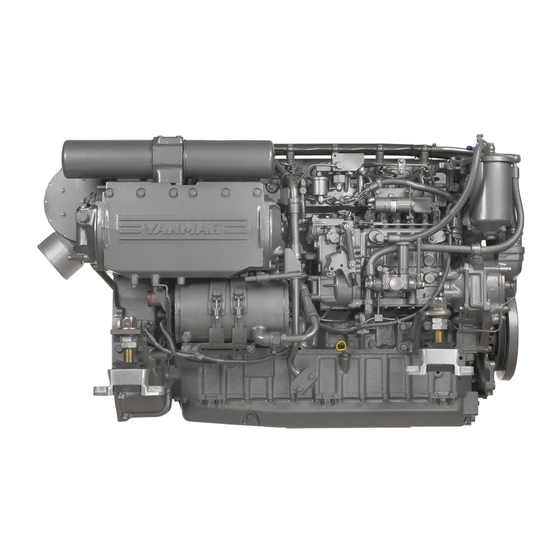
Page 1
HINSHI-H8001 SERVICE MANUAL MARINE DIESEL ENGINE 6LYA-UTE,STE...
This manual is also suitable for:
6lya-ste
Table of Contents
Print
Rename the bookmark
Delete bookmark?
Delete from my manuals?
Login
Sign In
OR
Sign in with Facebook
Sign in with Google
Upload manual
Upload from disk
Upload from URL