Table of Contents
Advertisement
Quick Links
Advertisement
Table of Contents

Related Manuals for Brady Bradyprinter THT 300X-Plus II


Summary of Contents for Brady Bradyprinter THT 300X-Plus II
- Page 1 Br adyprinter ™ 300X-Plus II 360X-Plus II 600X-Plus II...
- Page 2 © 2004 Brady Worldwide Inc. This copyrighted guide and the label printers described herein are licensed to Brady Corporation. All rights are reserved. Unauthorized reproduction of the guide or the software in the label printer may result in imprisonment of up to one year and fines of up to $10,000 (17 U.S.C.506).
-
Page 3: Table Of Contents
Table of Contents Proprietary Statement........v Product Improvements . - Page 4 Table of Contents 1 • Chapter 1 • Introduction1 Exterior View ........... . 2 Front Panel .
- Page 5 Table of Contents Media and Ribbon Sensor Calibration ......34 Transmissive (Media) Sensors........36 Adjust the Printhead .
- Page 6 Table of Contents Printhead and Platen Roller ........103 Sensors .
-
Page 7: Proprietary Statement
Proprietary Statement This manual contains proprietary information of Brady Corporation. It is intended solely for the information and use of parties operating and maintaining the equipment described herein. Such proprietary information may not be used, reproduced, or disclosed to any other parties for any other purpose without the expressed written permission of Brady Corporation. -
Page 8: Canadian Doc Compliance Statement
Brady Corporation has been advised of the possibility of such damages. Some jurisdictions do not allow the exclusion or limitation of incidental or consequential damages, so the above limitation or exclusion may not apply to you. -
Page 9: Declaration Of Conformity
73/23/EEC LVD Directive, EN60950:2000, CB Scheme FCC Part 15, Subpart B, Class B, FCC Part 15.247, IC RSS-210 NOM 019-SCFI-1998 C-TICK Manufactured for: Brady Corporation 6555 W. Good Hope Road Milwaukee, WI 53223, USA Effective Date: 1 January 2002 Bradyprinter THT X-Plus II Series User Guide... - Page 10 viii Bradyprinter THT X-Plus II Series User Guide...
-
Page 11: Warranty Information
In the event equipment is not so packaged, or if shipping damage is evident, it will not be accepted for service under warranty. Surface transportation charges for return to customers in the continental United States is paid by Brady Corporation. Otherwise, Brady Corporation pays CPT (carriage paid to) nearest airport;... - Page 12 Brady Corporation’s labor and material charges required to repair the defect. The warranty becomes void if the printhead is physically worn or damaged;...
-
Page 13: Supplies Products
(12) months for media and twelve (12) months for ribbon from the date of shipment by Brady Corporation. This is provided the user has complied with storage guidelines, handling, and usage of the supplies in Brady Corporation printers. - Page 14 Corporation is authorized to make any guaranty, warranty, or representation that contradicts the foregoing. Any waiver, alteration, addition, or modification to the foregoing warranties must be in writing and signed by an executive officer of Brady Corporation to be valid.
-
Page 15: Printer Software And Firmware License Agreement
AND PLEASE PROMPTLY RETURN THE PRINTER, ENCLOSURES AND ALL PACKAGING FOR A FULL REFUND. Brady Corporation (“Brady”) grants you a non-exclusive, non-transferable license to use the Software and Firmware embedded in the printer and the accompanying documentation according to the following terms: 2. - Page 16 Software and/or Firmware). In the event that Brady offers a replacement or modified version of or any upgrade to the Software and/or Firmware, (a) your continued use of the Software and/or...
- Page 17 5. PROPRIETARY RIGHTS. All title and copyrights in and to the Software, Firmware, the accompanying printed materials, and any copies of the Software and Firmware, are owned by Brady or its suppliers. All title and intellectual property rights in and to the content which may be accessed...
- Page 18 ARE OFFERED “AS IS” AND WITH ALL FAULTS AND ALL THE FOREGOING DISCLAIMERS AND LIMITATIONS CONTAINED IN THIS PARAGRAPH APPLY TO SUCH EMULATION LIBRARIES. 9. EXCLUSION OF ALL DAMAGES. TO THE MAXIMUM EXTENT PERMITTED BY APPLICABLE LAW, IN NO EVENT SHALL BRADY OR SUPPLIERS LICENSORS LIABLE...
- Page 19 Brady shall therefore be entitled to obtain an injunction against such breach from any court of competent jurisdiction immediately upon request without posting bond. Brady’s right to obtain injunctive relief shall not limit its right to seek further remedies.
- Page 20 15. CONFIDENTIAL INFORMATION. You acknowledge that the Software and Firmware embody confidential information owned by Brady and/or its licensors. To the extent you have access to any such information, you agree to use such information only for the authorized use of the Software and Firmware. You further...
-
Page 21: Preface
Preface This section provides you with contact information, document structure and organization, and additional reference documents. Contents Contacts ......... . xx Support . -
Page 22: Contacts
Preface Contacts Contacts You can contact Brady Corporation at any of the following: Visit us at: www.bradyid.com Our Mailing Address: Brady Worldwide Identification Solutions 6555 West Good Hope Road P.O. Box 2131 Milwaukee, WI 53201-2131 Telephone: +1.800.537.8791 Fax: +1 800.292.2289... -
Page 23: About This Document
The X-Plus II Series User Guide contains the following chapters and appendices: Chapter Title Content Number Warranty Information Warranty information on Brady printers, related hardware, and supplies. Introduction Printer overview, printer components, types of labels, and system considerations. Getting Started Instructions for setting up your printer. -
Page 24: Document Conventions
Ztools Files and Directories All file names and directories appear in Courier New font. For example, the Brady<version number>.tar file and the /root directory. Cautions, Important, Note, and Example Caution • Warns you of a potential electric shock situation. - Page 25 Preface Document Conventions Important • Advises you of information that is essential to complete a task. Note • Indicates neutral or positive information that emphasizes or supplements important points of the main text. Example • Provides an example, often a scenario, to better clarify a section of text. Tools •...
- Page 26 Preface Document Conventions SETUP/EXIT button xxiv Bradyprinter THT X-Plus II Series User Guide...
-
Page 27: Related Documents
Preface Related Documents Related Documents In addition to the X-Plus II Series User Guide, the following documents might be helpful references: ® • ZPL II Programming Guide Volume I (part number 45541L) and Volume II (part number 45542L). • PrintServer II™ Installation and User Guide (part number 45537L). •... - Page 28 Preface Related Documents xxvi Bradyprinter THT X-Plus II Series User Guide...
- Page 29 HAPTER Introduction This chapter provides a high-level overview of the printer and its components. Contents Exterior View ........2 Front Panel .
-
Page 30: Exterior View
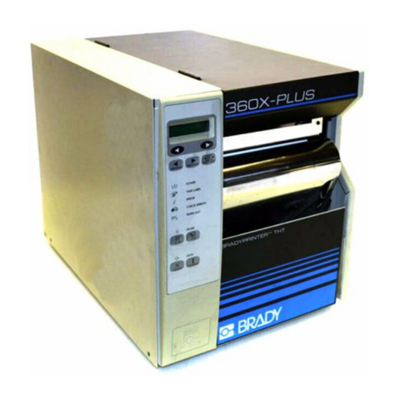
Introduction Exterior View Exterior View The following illustrations show the exterior of the printer. Front panel Media door Electronics cover Power switch AC power cord connection Bradyprinter THT X-Plus II Series User Guide... -
Page 31: Front Panel
Introduction Front Panel Front Panel This illustration shows the buttons and lights on the front panel. For details, see Front Panel Buttons on page 4 and Front Panel Lights on page Bradyprinter THT X-Plus II Series User Guide... -
Page 32: Front Panel Buttons
Introduction Front Panel Front Panel Buttons This table describes the function of the buttons shown in the illustration on page Button Details LEFT OVAL Changes parameter values. Common uses are to increase/decrease a value, answer yes or no, indicate on or off, scroll through several choices, input the password, or set up the printer for a firmware download. -
Page 33: Front Panel Lights
Introduction Front Panel Front Panel Lights This table details the lights shown in the illustration on page Light Details POWER Indicates printer power status. • Off — printer is off. • On — printer is on. • Off — Normal operation. TAKE LABEL •... -
Page 34: Printer Components
Introduction Printer Components Printer Components This illustration shows a side view of the printer’s internal components. Note • Depending on the printer options that you selected, your printer could look slightly different. For more about printer options, go to www.bradyid.com. Bradyprinter THT X-Plus II Series User Guide... - Page 35 Introduction Printer Components Printhead lever Ribbon take-up spindle Ribbon supply spindle Ribbon dancer assembly (only on select models) Media guide Media dancer roller assembly Media supply guide Media supply hanger Rewind spindle (optional) Spindle hook Lower roller Snap plate Platen roller Tear-off bar Bradyprinter THT X-Plus II Series User Guide...
- Page 36 Introduction Printer Components Bradyprinter THT X-Plus II Series User Guide...
- Page 37 HAPTER Getting Started This chapter provides the tasks that you must complete and the issues that you must consider before you load and configure your printer. Contents Before You Begin ........10 Unpack and Inspect the Printer .
-
Page 38: Before You Begin
Getting Started Before You Begin Before You Begin Review this checklist, and resolve any issues before you begin setting up your printer. When you are ready, continue with Printer Operation on page Unpack and Inspect Have you unpacked the printer and inspected it for damage? If you have not, see Unpack and Inspect the Printer on page Select a Site Have you selected an appropriate location for the printer? If you... -
Page 39: Unpack And Inspect The Printer
If you discover shipping damage upon inspection: • Immediately notify the shipping company of the damage, and file a damage report with them. Brady is not responsible for any damage incurred during shipment of the equipment and does not repair this damage under warranty. -
Page 40: Select A Site For The Printer
Getting Started Select a Site for the Printer Select a Site for the Printer Consider the following when selecting an appropriate location for your printer. Select a Surface Select a solid, level surface of sufficient size and strength to accommodate the printer and other equipment (such as a computer), if necessary. -
Page 41: Connect The Printer To A Power Source
Getting Started Connect the Printer to a Power Source Connect the Printer to a Power Source Caution • For personnel and equipment safety, always use an approved three-conductor power cord specific to the region or country intended for installation. This cord must use an IEC 320 female connector and the appropriate region-specific three-conductor grounded plug configuration. - Page 42 Getting Started Connect the Printer to a Power Source • The AC power plug and the IEC 320 connector must bear the certification mark of at least one of the known international safety organizations shown in this illustration. Bradyprinter THT X-Plus II Series User Guide...
-
Page 43: Communication Interfaces
Getting Started Communication Interfaces Communication Interfaces The way that you connect your printer to a data source depends on the communication options installed in the printer. The standard communication interfaces are an RS-232 serial data port, a bi-directional parallel port, and a USB 2.0 port. Note •... -
Page 44: Data Cable Requirements
• Do not tie the data cables to power wire conduits. Note • Brady printers comply with FCC Rules and Regulations, Part 15 for Class B Equipment using fully shielded, 6.5 ft (2 m) data cables. Use of unshielded cables may increase radiation above the Class B limits. -
Page 45: Types Of Media
The printer can use media that is on rolls or in fan-folded stacks. The difference between media types is in whether the media is continuous or non-continuous. We strongly recommend the use of Brady-brand supplies for continuous high-quality printing. A wide range of paper, polypropylene, polyester, and vinyl stock has been specifically engineered to enhance the printing capabilities of the printer and to ensure against premature printhead wear. -
Page 46: Non-Continuous Web Media
Getting Started Types of Media Non-Continuous Web Media Non-continuous web media refers to individual labels that are separated by a gap, notch, or hole. When you look at the media, you can tell where one label ends and the next one begins. Important •... -
Page 47: Ribbon
Getting Started Ribbon Ribbon The media determines whether you need to use ribbon and determines the minimum width of the ribbon. Consider the following: • Thermal transfer — ribbon needed. The ribbon must be as wide as or wider than the media being used. If the ribbon is narrower than the media, areas of the printhead are unprotected and subject to premature wear. - Page 48 Getting Started Ribbon Bradyprinter THT X-Plus II Series User Guide...
- Page 49 HAPTER Printer Operation If you have completed the tasks and resolved the issues in the checklist in Before You Begin on page 10, follow the instruction in this chapter to load and calibrate your printer and to print a configuration label. Contents Load the Printer.
-
Page 50: Load The Printer
Printer Operation Load the Printer Load the Printer This section gives you a series of instructions to load labels and ribbon (if used). The instructions that follow are for a standard printer in Tear-Off Mode. To choose different printing modes, see Print Modes on page Caution •... - Page 51 Printer Operation Load the Printer To load roll media, complete these steps: 1. Open the printhead. 2. Slide the media guide away from the printer frame. You might need to loosen the media guide screw. 3. Put the roll of media on the media hanger. 4.
-
Page 52: Load Fanfold Media
Printer Operation Load the Printer Load Fanfold Media Fanfold media feeds through either the bottom or rear access slot from outside the printer. The media hanger and media supply spindle are not used with fanfold media. To load fanfold labels, complete these steps: 1. - Page 53 Printer Operation Load the Printer • From the rear slot in the printer body. This illustration shows the printer with fanfold labels loaded through the rear slot. Printhead lever (shown in the Open position) Media guide Fanfold labels 4. Do you have the Cutter option? •...
-
Page 54: Load Ribbon
Printer Operation Load the Printer Load Ribbon Before you load ribbon, make sure that the labels that you are using need ribbon. Only thermal transfer labels require ribbon. Do not load ribbon if the printer is to be used with direct thermal labels. Caution •... - Page 55 Printer Operation Load the Printer To load the ribbon, complete these steps: 1. Align the segments of the ribbon supply spindle as shown in the following illustration. 2. Place the roll of ribbon on the ribbon supply spindle, and push the core as far back as it can go.
- Page 56 Printer Operation Load the Printer 5. Pull the ribbon leader over the printhead and above the top roller as shown in the following illustration. Ribbon leader Printhead 6. Bring the ribbon leader and ribbon under the ribbon take-up spindle, and wrap them around the spindle.
- Page 57 Printer Operation Load the Printer 8. Close the printhead. The following illustration shows how your printer should look with the media and ribbon loaded. 9. To remove the ribbon, refer to Remove Used Ribbon on page Bradyprinter THT X-Plus II Series User Guide...
-
Page 58: Remove Used Ribbon
Printer Operation Load the Printer Remove Used Ribbon When the ribbon has run out or must be changed, remove the used ribbon from the take-up spindle. This illustration shows the ribbon take-up spindle. Used ribbon Ribbon take-up spindle Ribbon release bars Notch in ribbon take-up spindle Arrow on ribbon take-up spindle Ribbon release knob... -
Page 59: Print A Configuration Label
Printer Operation Print a Configuration Label Print a Configuration Label When you have loaded the media and ribbon (if necessary), print a configuration label to use as a record of your printer settings. Keep the configuration label for baseline information on your printer when troubleshooting printing problems. Caution •... - Page 60 Printer Operation Print a Configuration Label 7. Did the label print? • Yes, a configuration label printed. Connect the printer to your data source. Communication can be handled in many different ways. More information about the standard interfaces is available in Standard Ports on page •...
-
Page 61: Calibrate The Printer
To upgrade your firmware or to check if you have the latest version, go to http://www.bradyid.com/brady/isdwebv2.nsf/webpages/downloads. • Sensor Profile Calibration, which you select through the front panel, auto-calibrates the printer and prints a media sensor profile. See Sensor Profile on page 83 for instructions. -
Page 62: Adjust Sensors
Printer Operation Adjust Sensors Adjust Sensors This section describes how to adjust and calibrate sensors. Media and Ribbon Sensor Calibration Media and ribbon sensor calibration is one of the most common adjustments to the printer settings. This procedure is performed through the front panel. Indications that the sensitivity may need to be reset are: •... - Page 63 Printer Operation Adjust Sensors 8. Press the right oval to continue. The message CALIBRATING PLEASE WAIT displays. The printer adjusts the scale (gain) of the signals that it receives from the media and ribbon sensors. On the sensor profile, this essentially corresponds to moving the peak of the graph up or down to optimize the readings for your application (for more information, see Sensor Profile on page...
-
Page 64: Transmissive (Media) Sensors
Printer Operation Adjust Sensors Transmissive (Media) Sensors The transmissive sensor consists of two sections: a light source (the lower media sensor) and a light sensor (the upper media sensor). The media passes between the two. The upper media sensor can be positioned along the inside half of the media (the side closest to the back of the printer) or the outside half of the media (the side farthest from the back of the printer). - Page 65 Printer Operation Adjust Sensors To adjust the upper media sensor for the outside half of the media: 1. Remove the ribbon (if ribbon is used). 2. Locate the upper media sensor. The upper media sensor eye is directly below the adjustment screw head.
- Page 66 Printer Operation Adjust Sensors To adjust the lower media sensor, complete these steps: 1. Locate the lower media sensor assembly under the rear roller. (The sensor is a spring clip holding a circuit board.) Lower media sensor 2. Slide the sensor until the two brass-colored infrared emitters are under the upper media sensor.
-
Page 67: Adjust The Printhead
Printer Operation Adjust the Printhead Adjust the Printhead Important • Print quality depends on the labels and ribbon used as well as the toggle pressure. Make sure your labels and ribbon are right for your application. • Direct thermal labels do not need ribbon. •... - Page 68 Printer Operation Adjust the Printhead Locking nuts Adjusting nuts 4. Some media types require higher pressure to print well. For these media types, increase or decrease pressure using the adjusting nuts until the left and right edges of the printed area are equally dark. 5.
- Page 69 HAPTER Print Modes This chapter describes the available print modes. Contents Select a Print Mode ........42 Tear-Off Mode .
-
Page 70: Select A Print Mode
Print Modes Select a Print Mode Select a Print Mode The options on your printer may let you set up additional print modes. Use the front panel controls to set up the printer to the print mode that you wish to use. The following are the available print mode selections: •... -
Page 71: Peel-Off Mode
Print Modes Select a Print Mode Peel-Off Mode Peel-Off Mode advances one label at a time. The printer does not print another label until the first label is removed. The TAKE LABEL light flashes until the label is removed. The backing is wound on the rewind spindle, but the rewind plate is not used. - Page 72 Print Modes Select a Print Mode To set up the printer in Peel-Off Mode, complete these steps: 1. Remove the rewind plate (if installed) from the front of the printer. Store it on the two mounting screws on the inside of the front panel. 2.
-
Page 73: Cutter Mode
Print Modes Select a Print Mode Cutter Mode A cutter is a rotating knife with a self-sharpening blade that is attached to the front of the printer. The cutter is used to cut individual labels as they are printed. See www.bradyid.com for more information about the cutter option. - Page 74 Print Modes Select a Print Mode Caution • The cutter blade is sharp. Do not rub or touch the blade with your fingers. 9. Feed the labels through the cutter mechanism. 10. Flip up the media supply guide. 11. Slide in the media guide and media supply guide so they just touch, but do not restrict, the edge of the roll.
-
Page 75: Rewind Mode
Print Modes Select a Print Mode Rewind Mode Rewind Mode allows the media to be wound on a core after printing. The following illustration shows the printer loaded with labels in Rewind Mode. Printhead lever Media guide Media supply guide Labels Guide plate Spindle hook... - Page 76 Print Modes Select a Print Mode To install the rewind plate, complete these steps: 1. Remove the rewind plate from its storage location inside the printer. 2. Position the rewind plate so that the lip on the attached hook plate points down. 3.
- Page 77 Print Modes Select a Print Mode To set up the printer in Rewind Mode, complete these steps: 1. If you have not already done so, install the rewind plate. 2. From the front panel, select Rewind Mode. 3. Open the printhead. 4.
-
Page 78: Rewind Mode With Cutter Option
Print Modes Select a Print Mode Rewind Mode with Cutter Option Printers with the cutter option can use the Rewind Mode to print and save a roll of labels. See www.bradyid.com for more information about the cutter option. Note • Rewind Mode cannot be used with the cutter option on the BP THT 300X-Plus II and 600X-Plus II. - Page 79 Print Modes Select a Print Mode To set up the Rewind Mode for printers with the cutter option, complete these steps: 1. Turn the printer On (I). The printer feeds out and cuts one label. 2. From the front panel, select Rewind Mode. 3.
- Page 80 Print Modes Select a Print Mode 21. Slide in the media guide and media supply guide so they just touch, but do not restrict, the edge of the roll. 22. Before closing the printhead, make sure that: • The labels are positioned against the inside guides. •...
-
Page 81: Remove Backing From Rewind Spindle
Print Modes Remove Backing from Rewind Spindle Remove Backing from Rewind Spindle Rewind Mode and Peel-Off Mode use the rewind spindle. The label backing must be removed every time you change labels for the printer to work correctly. Important • It is not necessary to turn off the power to remove backing from the rewind spindle. - Page 82 Print Modes Remove Backing from Rewind Spindle Bradyprinter THT X-Plus II Series User Guide...
- Page 83 HAPTER Data Ports This chapter describes the standard communication ports on the printer. Contents Standard Ports........56 Parallel Port.
-
Page 84: Standard Ports
Data Ports Standard Ports Standard Ports The different ports available to connect the printer to your computer or network include: • Parallel • Serial RS-232 • USB Parallel Port When communicating via the parallel port, the values selected must be the same as those used by the host equipment connected to the printer. - Page 85 Data Ports Standard Ports The following table shows the pin configuration and function of a standard computer- to-printer parallel cable. 36-Pin Description Connectors nStrobe/HostClk 2–9 Data Bits 1–8 nACK/PtrClk Busy/PtrBusy PError/ACKDataReq Select/Xflag nAutoFd/HostBusy Not used 16, 17 Ground +5 V at 750 mA The maximum current draw may be limited by option configuration.
-
Page 86: Serial Port
Data Ports Standard Ports Serial Port To communicate using the serial data port of the printer, you must choose the number of data and stop bits, parity, and handshaking. Parity applies only to data transmitted by the printer because the parity of received data is ignored. The values selected must be the same as those used by the host equipment connected to the printer. -
Page 87: Serial Pin Configuration
Data Ports Standard Ports Serial Pin Configuration The table below shows the pin configuration and function of the rear panel serial data connector on the printer. Pin No. Name Description — Not connected Receive data—data input to printer Transmit data—data output from printer Data terminal ready—output from printer Signal ground Data set ready—input to printer... - Page 88 Data Ports Standard Ports RS-232 Interface Connections Direct Connection to a Computer The printer is configured as Data Terminal Equipment (DTE). Note • The cable used to connect the printer to a computer must be a null modem (crossover) cable. To connect the printer to any other DTE devices, use a null modem cable.
- Page 89 Data Ports Standard Ports DB-9 to DB-25 Connections An interface adapter is required to connect the printer’s DB-9 interface to a DB-25 connector. A generic DB-25 adapter CAN be used, although the +5 VDC signal source would not be passed through the adapter. This illustration shows the connections required for the DB-9 to DB-25 interface.
-
Page 90: Modem Connection
Data Ports Standard Ports Modem Connection When the printer is connected via its RS-232 interface to Data Communication Equipment (DCE) such as a modem, use a standard RS-232 (straight-through) interface cable. This illustration shows the connections required for this cable. (Printer) (Modem, etc.) RXD (receive data) - Page 91 Data Ports Standard Ports RS-422/RS-485 Interconnections Caution • A qualified service technician must install a jumper on the printer’s main logic board at JP1, pins 2 and 3, for the RS-422/RS-485 interface adapter to function properly. An interface adapter is required to connect the printer’s RS-232 DB-9 interface to a host computer through an RS-422 or RS-485 interface.
-
Page 92: Usb 2.0 Port
Data Ports Standard Ports USB 2.0 Port A USB 2.0 port (which is USB 1.1 and 1.0 compatible) is available to connect your printer to the host equipment. The industry-standard USB cable has an A-male connector on one end and a B-male connector on the other end as shown in the following illustration. -
Page 93: Memory Cards
HAPTER Memory Cards This chapter describes the optional cards that can be used with the printer and gives instructions for installation. Contents PCMCIA Card ........66 CompactFlash Card . -
Page 94: Pcmcia Card
Memory Cards PCMCIA Card PCMCIA Card A Type 1- or Type II-compliant PCMCIA card holds extra memory or font options for the printer. The card is hot-swappable (it can be installed while the printer is on). Caution • Observe proper electrostatic safety precautions when handling any static-sensitive components such as circuit boards and printheads. - Page 95 Memory Cards PCMCIA Card To install the PCMCIA card, complete these steps: 1. Remove the PCMCIA card shield from the rear of the printer as shown. 2. Insert the PCMCIA card, with the notch up, into the card slot as shown. Insert it far enough to make the eject button pop out.
-
Page 96: Compactflash Card
Memory Cards CompactFlash Card CompactFlash Card A CompactFlash card is a nonvolatile memory card that stores data even when the power to the printer is turned off. A Type I-compliant CompactFlash card holds extra memory or optional fonts for your printer. This illustration shows the parts of the printer used in this procedure. - Page 97 Memory Cards CompactFlash Card Caution • This procedure should only be performed by qualified service technicians. Caution • Observe proper electrostatic safety precautions when handling any static-sensitive components such as circuit boards and printheads. To install a CompactFlash card, complete these steps: 1.
- Page 98 Memory Cards CompactFlash Card 6. Reinstall the electronics cover by lowering the cover so the lip of the cover goes into the channel on the top of the printer. 7. Secure the cover by reinstalling the two screws near the bottom of the cover. 8.
- Page 99 HAPTER Front Panel Controls This appendix describes the function of the front panel. Contents Overview ......... . 72 Enter Setup Mode .
-
Page 100: Overview
Front Panel Controls Overview Overview After you have installed the labels and ribbon and printed a configuration label, you can change the printer’s settings using the front panel controls. For an overview of the front panel, including descriptions of the buttons and lights, see Front Panel on page 3. -
Page 101: Leave Setup Mode
Front Panel Controls Overview Leave Setup Mode To leave Setup Mode, complete these steps: 1. Press SETUP/EXIT . The LCD displays SAVE CHANGES. 2. Press the left or right oval to display the save choices. The choices are described in the following table. -
Page 102: Password-Protected Parameters
Front Panel Controls Password-Protected Parameters Password-Protected Parameters Certain parameters are password-protected by factory default, including the communication parameters. Note • If the parameters are set incorrectly, the printer may function unpredictably. The first attempt to change a password-protected parameter (pressing one of the ovals) requires you to enter a four-digit password at the ENTER PASSWORD display. -
Page 103: Default Password Value
Front Panel Controls Password-Protected Parameters Default Password Value The default password value is 1234. The password can be changed using the ^KP (Define Password) ZPL II instruction. Disable the Password Protection Feature You can disable the password protection feature so that it no longer prompts you for a password by setting the password to 0000 via the ^KPØ... -
Page 104: Front Panel Lcd
Front Panel Controls Front Panel LCD Front Panel LCD Use the LCD display on the front panel to adjust printer settings. In the following table, parameters are shown in the order in which they are displayed when you press NEXT/SAVE after entering setup mode. Throughout this process, press NEXT/SAVE to continue to the next parameter, or press PREVIOUS to return to the previous parameter in the cycle. - Page 105 Front Panel Controls Front Panel LCD Description Adjusting Print Speed PRINT SPEED Slower print speeds typically yield better print quality. Print speed changes take effect upon exiting the menu mode. • Press the right oval to increase print speed. • Press the left oval to decrease print speed. Default: 2 ips Range: 2 ips to +12 ips (depends on specific printer) Adjusting the Tear-Off Position...
- Page 106 Front Panel Controls Front Panel LCD Description Setting Media Type MEDIA TYPE This parameter tells the printer the type of media that you are using. Selecting continuous media requires that you include a label length instruction in your label format (^LLxxxx if you are using ZPL or ZPL II). When non-continuous media is selected, the printer feeds media to calculate label length (the distance between two recognized registration points of the inter-label gap, webbing, or alignment notch or hole).
- Page 107 Front Panel Controls Front Panel LCD Description Setting Print Width PRINT WIDTH Print width determines the printable area across the width of the label. To change value shown: 1. Press the left oval to move the cursor. 2. Press the right oval to increase the value of the digit. Note •...
- Page 108 Front Panel Controls Front Panel LCD Description EARLY WARNING Setting Early Warning When this parameter is enabled, the printer provides warnings when labels or ribbons are running low or when the printhead needs to be cleaned. Note • Labels per roll and ribbon length need to be updated when beginning use of the Early Warning System.
- Page 109 Front Panel Controls Front Panel LCD Description Setting Labels Per Roll LABELS PER ROLL This parameter needs to be updated when setting the Early Warning System so the printer can provide early warnings when labels are running low. • Press the right or left oval to display other choices. Default: 900 labels Range: 100 labels to 9999 labels RIBBON LENGTH Setting Ribbon Length...
- Page 110 Front Panel Controls Front Panel LCD Description List All LIST ALL • Press the right oval to print a label that lists the available fonts, bar codes, images, formats, and the current printer configuration. Initialize Memory Card INITIALIZE CARD Caution • Perform this operation only when it is necessary to erase all previously stored information from the memory card.
- Page 111 Front Panel Controls Front Panel LCD Description INIT FLASH MEM Initialize Flash Memory Caution • Perform this operation only when it is necessary to erase all previously stored information from Flash memory. 1. When the LCD displays INITIALIZE CARD , press the right oval to select YES . (If you are prompted for a password, enter your password using the instructions on page 74 in Password-Protected Parameters...
- Page 112 Front Panel Controls Front Panel LCD Description Calibrate Media and Ribbon Sensors MEDIA AND RIBBON Use this procedure to adjust sensitivity of media and ribbon sensors. CALIBRATE Important • This procedure must be followed exactly as presented. All of the steps must be performed even if only one of the sensors requires adjustment.
- Page 113 Front Panel Controls Front Panel LCD Description Setting Parallel Communications PARALLEL COMM Select the communications port that matches the one being used by the host computer. • Press the right or left oval to display other choices. Default: Bidirectional Selections: Bidirectional, unidirectional, or Twinax/coax Setting Serial Communications SERIAL COMM Select the communications port that matches the one being used by the host...
- Page 114 Front Panel Controls Front Panel LCD Description Setting Parity PARITY The parity of the printer must match the parity of the host computer for accurate communications to take place. Select the parity that matches the one being used by the host computer. •...
- Page 115 Front Panel Controls Front Panel LCD Description Setting Network ID NETWORK ID Network ID is used to assign a unique number to a printer used in an RS-422/RS-485 network. This gives the host computer the means to address a specific printer. If the printer is used in an RS-422/RS-485 network, you must select a network ID number.
- Page 116 Front Panel Controls Front Panel LCD Description Control Prefix Character CONTROL PREFIX The printer looks for this two-digit hex character to indicate the start of a ZPL/ZPL II control instruction. Note • Do not use the same hex value for the control, format, and delimiter character.
- Page 117 Front Panel Controls Front Panel LCD Description Selecting ZPL Mode ZPL MODE The printer remains in the selected mode until it is changed by this front panel instruction or by using a ZPL/ZPL II command. The printer accepts label formats written in either ZPL or ZPL II. This eliminates the need to rewrite any ZPL formats you already have.
- Page 118 Front Panel Controls Front Panel LCD Description Backfeed Sequence BACKFEED This parameter establishes when and how much label backfeed occurs after a label is removed or cut in Peel-Off, Cutter, and Applicator Modes. It has no effect in Rewind or Tear-Off Modes. This parameter setting can be superseded by the ~JS instruction when received as part of a label format (see the ZPL II Programming Guide).
- Page 119 Front Panel Controls Front Panel LCD Description Adjusting Left Position LEFT POSITION This parameter establishes how far from the left edge of a label the format begins to print by adjusting horizontal positioning on the label. Positive numbers adjust the printing to the left by the number of dots selected, negative numbers shift printing to the right.
- Page 120 Front Panel Controls Front Panel LCD Description Setting the Head Test Count HEAD TEST COUNT The printer periodically performs a test of the printhead functionality, called a printhead test or head test. This parameter establishes how many labels are printed between these internal tests. 1.
- Page 121 Front Panel Controls Front Panel LCD Description HEAD RESISTOR Setting the Head Resistor Value Caution • This parameter should be changed only by qualified service personnel. Do not set the value higher than that shown on the printhead. Setting a higher value may damage the printhead. This value has been preset at the factory to match the resistance value of the printhead.
- Page 122 Front Panel Controls Front Panel LCD Description Setting the Applicator Port APPLICATOR PORT Determines the action of the verifier port. Note • Set this value as suggested by the applicator manufacturer. • Off: The applicator port is off. • Mode 1: Asserts the ~END_PRINT signal low while the printer is moving the label forward.
- Page 123 Front Panel Controls Front Panel LCD Description RESYNCH MODE Resynch Mode This parameter determines how the printer reacts if the label synchronization is lost and the label top is not where expected. • Feed Mode—If the label top is not where expected, the printer feeds a blank label to find the label top position.
- Page 124 Front Panel Controls Front Panel LCD Description LCD Adjustment LCD ADJUST This parameter allows you to adjust the contrast of your LCD if it is difficult to read. 1. Press the left oval to move the cursor. 2. Press the right oval to toggle +/- or to increase the value of the digit. Range: 00 to 19 Format Convert FORMAT...
- Page 125 Front Panel Controls Front Panel LCD Description RTC (Real-time clock) Time RTC TIME This parameter allows you to set the time following the convention selected in IDLE DISPLAY. 1. Press the left oval to move to the next digit position. 2.
-
Page 126: Zebranet ® Printserver Ii Option Display
Front Panel Controls Front Panel LCD ® ZebraNet PrintServer II Option Display ® These menu options display only if you have a ZebraNet PrintServer II installed. Explanation IP Resolution IP RESOLUTION Depending on the selection, allows either the user (permanent) or the server (dynamic) to select the IP address. - Page 127 Front Panel Controls Front Panel LCD Explanation Subnet Mask SUBNET MASK This parameter selects the part of the IP address that is considered to be part of the local network. It can be reached without going through the default gateway. •...
- Page 128 Front Panel Controls Front Panel LCD Bradyprinter THT X-Plus II Series User Guide...
- Page 129 HAPTER Routine Maintenance Cleaning your printer regularly maintains print quality and may extend the life of the printer. This appendix provides routine cleaning and maintenance procedures. Contents Cleaning Schedule ....... . . 102 Clean Exterior .
-
Page 130: Cleaning Schedule
The recommended cleaning schedule is shown in the table below. See the following pages for specific procedures. Caution • Use only the cleaning agents indicated. Brady is not responsible for damage caused by any other fluids being used on this printer. -
Page 131: Clean Exterior
Routine Maintenance Clean Exterior Clean Exterior Clean the outside surfaces of the printer with a lint-free cloth. Use a mild detergent solution or desktop cleaner sparingly, as needed. Caution • Do not use harsh or abrasive cleaning agents or solvents. Clean Interior After every four rolls of labels, inspect the inside of the printer. - Page 132 Routine Maintenance Clean Interior Caution • The printhead is hot and can cause severe burns. Allow the printhead to cool. Caution • Observe proper electrostatic safety precautions when handling any static- sensitive components such as circuit boards and printheads. To clean the printhead and platen roller, complete these steps: 1.
-
Page 133: Sensors
Note • If print quality does not improve when you perform this procedure, clean the printhead with Save-a-Printhead cleaning film. This specially coated material removes contamination buildup without damaging the printhead. Call an authorized Brady distributor for more information. Sensors Brush or vacuum any accumulated paper lint and dust off the sensors whenever the sensors are blocked. - Page 134 Routine Maintenance Clean Interior Transmissive (Media) Sensor Locations Upper and lower transmissive (media) sensors are shown in the following illustrations. Upper media sensor Lower media sensor Bradyprinter THT X-Plus II Series User Guide...
-
Page 135: Snap Plate
Routine Maintenance Clean Interior Snap Plate Clean the snap plate when label adhesive or a label is stuck to the underside of the snap plate. This illustration shows snap plate and the loops on either side. Left loop Snap plate Right loop To clean the snap plate, complete these steps: 1. -
Page 136: Cutter
Routine Maintenance Clean Interior 7. To reinstall the snap plate, insert the two tabs on the bottom of the snap plate into the two slots of the media path. 8. Slide the snap plate toward you. 9. Press down on the loops to lock the snap plate into place. Cutter If the cutter is not cutting the labels cleanly or if it jams with labels, clean the cutter. -
Page 137: Replace Fuse
Routine Maintenance Replace Fuse Replace Fuse The instructions that follow are for the BP THT 360X-Plus II series printers only. The BP THT 300X-Plus II and BP THT 600X-Plus II fuses must be replaced only by an authorized service technician. Caution •... - Page 138 2. Remove the faulty fuse and install a new fuse in the in-circuit position as shown. Important • If you use the spare fuse, be sure to order a replacement fuse from an authorized Brady distributor. The spare fuse should be the exact type and rating as the original in-circuit fuse.
- Page 139 HAPTER Troubleshooting This chapter provides you with information about LCD, print quality, communications, and other errors that you might need to troubleshoot. Contents Troubleshooting........112 LCD Error Messages.
-
Page 140: Troubleshooting
Troubleshooting Troubleshooting Troubleshooting If an error condition exists with the printer, review this checklist: Is there an error message on the LCD? If yes, see LCD Error Messages on page 113 for more information. Is the CHECK RIBBON light on when ribbon is loaded properly or are non-continuous labels are being treated as continuous labels? If yes, see Media and Ribbon Sensor Calibration on page... -
Page 141: Lcd Error Messages
Troubleshooting LCD Error Messages LCD Error Messages The LCD displays messages when there is an error. This table identifies LCD errors, the possible causes, and the recommended solutions. Possible Cause Recommended Solution Thermal Transfer Mode— Load the ribbon correctly, following Ribbon Out Ribbon is not loaded or is directions in Load Ribbon... - Page 142 Troubleshooting LCD Error Messages Possible Cause Recommended Solution The printhead is not fully Close the printhead. HEAD OPEN closed. • If the failed elements affect your HEAD ELEMENT BAD One or more of the printhead elements failed the printhead printing application, replace the element test.
- Page 143 Troubleshooting LCD Error Messages Possible Cause Recommended Solution • To operate in Direct Thermal mode, Ribbon is loaded, but the RIBBON IN printer is set for Direct remove the ribbon. Thermal mode. • To operate in Thermal Transfer mode, leave the ribbon loaded and change the print method to Thermal Transfer.
- Page 144 Troubleshooting LCD Error Messages Possible Cause Recommended Solution The printhead requires Clean the printhead according to the CLEAN HEAD NOW cleaning. instructions in Printhead and Platen Roller on page 103. Caution • The printhead is hot and can cause severe burns. Allow the printhead to cool.
- Page 145 Troubleshooting LCD Error Messages Possible Cause Recommended Solution Cutter blade is in the media Turn off the printer power and unplug the CUTTER JAMMED path. printer. Inspect the cutter module for debris and clean as needed following the cleaning instructions in Cutter on page 108.
-
Page 146: Print Quality Problems
This table identifies problems with print quality, the possible causes, and the recommended solutions. Problem Possible Cause Recommended Solution General print quality You are using an Consult an authorized Brady distributor issues incorrect combination of for information and advice. labels and ribbon for your application. The printer is set at the For optimal print quality, set the print incorrect print speed. - Page 147 Troubleshooting Print Quality Problems Problem Possible Cause Recommended Solution There is light printing The toggle pressure Follow the instructions in Adjust the (or no printing) on the needs to be adjusted. Printhead on page left or right side of the label or the printed Caution •...
- Page 148 Troubleshooting Print Quality Problems Problem Possible Cause Recommended Solution Intermittent creases on There is too much toggle Reduce the toggle pressure. See Adjust the left and right edges pressure on the the Printhead on page of the labels printhead. Caution • Observe proper electrostatic safety precautions when handling any static- sensitive components such as...
-
Page 149: Communications Problems
Troubleshooting Communications Problems Communications Problems This table identifies problems with communications, the possible causes, and the recommended solutions. Problem Possible Cause Recommended Solution A label format was sent The communication Check the printer driver or software to the printer but was parameters are incorrect. - Page 150 Troubleshooting Communications Problems Problem Possible Cause Recommended Solution A label format was sent The prefix and delimiter Verify the prefix and delimiter characters. to the printer but was characters set in the See Format Prefix Character on page 88 not recognized. The printer do not match the and Delimiter Character on page 88...
-
Page 151: Printer Diagnostics
During either test sequence, the front panel LEDs light up and the LCD monitors the progress of the POST. If the printer fails any of these tests, FAILED shows on the LCD. If this occurs, notify an authorized Brady distributor. Additional Printer Self Tests These self tests produce sample printouts and provide specific information that help determine the operating conditions for the printer. -
Page 152: Cancel Self Test
Troubleshooting Printer Diagnostics CANCEL Self Test The CANCEL self test prints a configuration label, which tells you the current settings for the printer. To perform the CANCEL Self Test, complete these steps: 1. Turn Off (O) the printer. 2. Press and hold CANCEL while turning the power On (I). Hold CANCEL until the DATA light turns off. -
Page 153: Pause Self Test
Troubleshooting Printer Diagnostics PAUSE Self Test This self test can be used to provide the test labels required when making adjustments to the printer’s mechanical assemblies. See the sample printout below. To perform a PAUSE self test, complete these steps: 1. -
Page 154: Feed Self Test
Troubleshooting Printer Diagnostics FEED Self Test This test helps you choose the best darkness setting for your printer. To perform a FEED self test, complete these steps: 1. Turn Off (O) the printer. 2. Press and hold FEED while turning the power On (I). Hold FEED until the DATA light turns off. -
Page 155: Communications Diagnostics Test
Troubleshooting Printer Diagnostics FEED and PAUSE Self Test Performing this self test temporarily resets the printer configuration to the factory default values. These values are active only until power is turned off unless you save them permanently in memory. To perform a FEED and PAUSE self test, complete these steps: 1. - Page 156 Troubleshooting Printer Diagnostics Bradyprinter THT X-Plus II Series User Guide...
- Page 157 PPENDIX Specifications This appendix provides the features of and specifications for the BP THT X-Plus II printers. Contents Features ......... 130 Standard Features.
-
Page 158: Features
Specifications Features Features This section lists the standard and optional features for the printer. Standard Features Note • Printer specifications are subject to change without notice. • Thermal transfer and direct thermal printing • DRAM 16 MB • USB 2.0 Port •... -
Page 159: Bar Codes
Specifications Features • Mirror image printing • Four-position field rotation (0°, 90°, 180°, 270°) • Slew command • Controlled via mainframe, mini-computer, PC, portable data terminal • Programmable quantity with print, pause, and cut control • Communicates in printable ASCII characters •... -
Page 160: Agency Approvals For All Printers
Specifications Features • MSI • PDF-417 (2-dimensional bar code) • PLANET code • Plessey • POSTNET • QR-Code • RSS code • Standard 2 of 5 • TLC 39 • UPC-A, UPC-E, UPC extensions Agency Approvals for All Printers Approvals include: •... -
Page 161: General Specifications
Specifications General Specifications General Specifications The following table gives the general specifications for the printer by model number. Dimensions BP THT 300/600X-Plus II BP THT 360X-Plus II Height 15.5 in (393.7 mm) 15.5 in. (393.7 mm) Width 10.37 in. (263.5 mm) 13.15 in. -
Page 162: Environmental Conditions For Operation And Storage
Specifications General Specifications Environmental Conditions for Operation and Storage Environment Mode Temperature Relative Humidity Operation Thermal Transfer 41° to 104°F 20 to 85% non-condensing (5° to 40° C) Direct Thermal 32° to 104°F (0° to 40° C) Storage Thermal Transfer or –40°... -
Page 163: Print Specifications By Model
Specifications Print Specifications by Model Print Specifications by Model Refer to the key and the table that follows for printer specifications. Model Specifications Key This table contains the key for print specifications for the tables that follow. Non-Continuous printing (gap, notch, or hole between labels). Continuous printing (no gap, notch or hole). -
Page 164: Ribbon Specifications By Model
Specifications Ribbon Specifications by Model Ribbon Specifications by Model Refer to the table that follows for ribbon specifications for your type of printer. Note • Match the ribbon to the label width and printhead width that you are using. • Ribbon must be wound with the coated side out. •... -
Page 165: Label Specifications
Important • Media registration and minimum label length are affected by label type and width, ribbon type, print speed, and printer mode of operation. Performance improves as these factors are optimized. Brady recommends qualifying any application with thorough testing. Label Specification Key... - Page 166 Specifications Label Specifications Specifications BP THT 300X-Plus II BP THT 600X-Plus II Total thickness (includes 0.003 in. (0.076 mm) 0.003 in. (0.076 mm) backing, 0.012 in. (0.305 mm) 0.012 in. (0.305 mm) if any) Cutter maximum full-width 0.009 in. (0.23 mm) Does not apply media thickness Roll media core inside...
- Page 167 Specifications Label Specifications Black Mark Sensing Only Specifications BP THT 300X-Plus II BP THT 600X-Plus II Mark length (measuring 0.12 in. (3 mm) 0.12 in. (3 mm) parallel to label/tag edge) 0.43 in. (11 mm) 0.43 in. (11 mm) Mark width (measuring to 0.43 in.
-
Page 168: Bp Tht 360X-Plus Ii Printers
Important • Media registration and minimum label length are affected by label type and width, ribbon type, print speed, and printer mode of operation. Performance improves as these factors are optimized. Brady recommends qualifying any application with thorough testing. Label Specification Key... - Page 169 Specifications Label Specifications Specifications BP THT 360X-Plus II Preferred inter-label gap Maximum inter-label gap = 2 × (label length for which you have calibrated the printer) + 1 in. (25.4 mm) Maximum internal fanfold media pack size 8.0×7.1×4.5 in. (label + backing) L×W×H (203×114×114 mm) Ticket/tag sensing notch L×W 0.12×0.25 in.
- Page 170 Specifications Label Specifications Black Mark Sensing Only Specifications BP THT 360X-Plus II Mark length (measuring parallel to label or 0.12 in. (3 mm) tag edge) 0.43 in. (11 mm) Mark width (measuring to perpendicular label 0.43 in. (11 mm) or tag edge) Full media width Mark location Marks must be located within 0.040 in.
-
Page 171: Index
..... . 132 Brady support ......xx alert setting . - Page 172 Index checklist cutter before you begin ..... . 10 cleaning ......108 CUTTER JAMMED troubleshooting .
- Page 173 Index enter setup mode ......72 idle display setting ..... . 96 environmental specifications .
- Page 174 Index load the printer load fanfold media ..... 24 operating conditions ..... 12 load roll media .
-
Page 175: Print Quality
Index print modes printer settings Cutter Mode ......45 applicator port ......94 features . - Page 176 Index printer setup ribbon CHECK RIBBON before you begin ..... . 10 light on ....34 load the printer .
- Page 177 Index sensors adjusting ......34 take label setting ......95 cleaning .
- Page 178 Index web media ZPL Programming Language definition ......18 features ......130 setting sensor type .
- Page 180 Brady Worldwide Identification Solutions 6555 West Good Hope Road P.O. Box 2131 Milwaukee, WI 53201-2131 Telephone: +1 800.537.8791 Facsimile: +1 800.292.2289 Customer Order # 13383-12 Manufacturer Part # 13383LB-12 Rev. 1 © 2004 Brady Worldwide Inc.