Table of Contents
Advertisement
Advertisement
Chapters
Table of Contents

Related Manuals for Omron CP1E - INTRODUCTION


Summary of Contents for Omron CP1E - INTRODUCTION
- Page 1 W461-E2-02A...
- Page 3 CP1L-L10D - CP1L-L14D - CP1L-L20D - CP1L-M30D - CP1L-M40D - CP1L-M60D - CP1E-E D -A CP1E-N CP1L/CP1E CPU Unit Introduction Manual...
- Page 4 Other brand and product names are trademarks or registered trademarks of their respective owners. OMRON, 2009 All rights reserved. No part of this publication may be reproduced, stored in a retrieval system, or transmitted, in any form, or by any means, mechanical, electronic, photocopying, recording, or otherwise, without the prior written permission of OMRON.
-
Page 5: Table Of Contents
SECTION 2 Designing Systems ............21 Organization of this Manual ..................22 About the Shutter Control System ................24 I/O Allocation for the Shutter Control System ............26 Example Ladder Program..................28 SECTION 3 Mounting and Wiring............29 Installation Notes ...................... 30 Mounting onto DIN Tracks .................. - Page 6 Section 2 explains how to construct a CP1L system based on the shutter control system as an exam- ple. Section 3 explains the how to install CP1L onto a DIN track, how to wire power supply and I/O lines, and how to test operation as an example.
- Page 7 Related Manuals The following manuals are used for the CP-series CPU Units. Refer to these manuals as required. Cat. No. Manual name Description W462 SYSMAC CP Series CP1L Explains the system configuration, installation, wir- CPU Unit User’s Manual ing, I/O allocation, pulse/counter functions, and expansion unit connections in details.
- Page 8 Read and Understand this Manual Please read and understand this manual before using the product. Please consult your OMRON representative if you have any questions or comments. Warranty and Limitations of Liability WARRANTY OMRON's exclusive warranty is that the products are free from defects in materials and workmanship for a period of one year (or other period if specified) from date of sale by OMRON.
- Page 9 The following are some examples of applications for which particular attention must be given. This is not intended to be an exhaustive list of all possible uses of the products, nor is it intended to imply that the uses listed may be suitable for the products: •...
- Page 10 PERFORMANCE DATA Performance data given in this manual is provided as a guide for the user in determining suitability and does not constitute a warranty. It may represent the result of OMRON's test conditions, and the users must correlate it to actual application requirements.
-
Page 11: Precautions
General Precautions ........ -
Page 12: Intended Audience
This manual provides information for programming and operating the Unit. Be sure to read this manual before attempting to use the Unit and keep this manual close at hand for reference during operation. -
Page 13: Application Precautions
Caution With an CP1E E-type CPU unit or with an N-type CPU unit without a Battery, the contents of the DM Area (D) *, Holding Area (H), the Counter Present Values (C), the status of Counter Completion Flags (C), and the status of bits in the Auxiliary Area (A) related to clock functions may be unstable when the power supply is turned ON. - Page 14 Application Precautions...
-
Page 15: Cp1L/Cp1E Overview
SECTION 1 CP1L/CP1E Overview This section introduces the types of CP1L and CP1E, as well the part names used during operation. 1-1 CP1L/CP1E Models .............. 14 1-1-1 CP1L Models ..............14 1-1-2 CP1E Models..............15 1-2 Part Names and Functions ........... 17... -
Page 16: Cp1L/Cp1E Models
CP1L/CP1E Overview 1-1 CP1L/CP1E Models CP1L programmable controller is a PLC package type, available with 10, 14, 20, 30, 40 or 60 I/O points. The CP1E includes E-type CPU Units (basic models) for standard control operations using basic, movement, arithmetic, and comparison instructions, and N-type CPU Units (application models) that supports connections to Programmable Terminals, Inverters, and Servo Drives. -
Page 17: Cp1E Models
40-point I/O Units (CP1L-M40D - ) • CPU unit has 24 input points and 16 output points. • CP-series expansion I/O units can be used to add I/O points, up to a total of 160 I/O points. 1-1-2 CP1E Models 20-point I/O Units (CP1E- 20D - ) •... - Page 18 40-point I/O Units (CP1E- 40D - ) • CPU unit has 24 input points and 16 output points. • CP-series expansion I/O units can be used to add I/O points, up to a total of 160 I/O points. E-type CPU Unit...
-
Page 19: Part Names And Functions
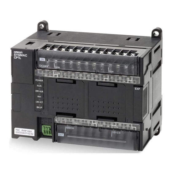
1-2 Part Names and Functions 1-2 Part Names and Functions This section describes the part names and functions, using the CP1L 14-point I/O unit and CP1E 40- point I/O unit as examples. CP1L14-point I/O Unit MEMORY COMM COMM CP1E 40-point I/O Unit... - Page 20 (4) External analog settings input connector (only CP1L) Takes an external input between 0 and 10V, and changes the value for auxiliary area A643CH to a value between 0 and 256. This input is not isolated. (5) DIP switches (only CP1L) Used for settings such as write-permission on user memory, automatic transfers from memory cassettes, and tool bus use.
- Page 21 • External power supply terminal: Units that use AC power supply have a 24VDC external power supply terminal with a maximum capacity of 300mA.This can be used as a service power supply for input devices. CP1E 20-point I/O units have no external power supply terminal.
- Page 22 • CP1E CPU units The user program, parameters, or specified DM Area words are being written to the backup memory (built-in EEPROM). Note: Do not turn the PLC power supply OFF while this indicator is lit. Not lit Any other state.
-
Page 23: Designing Systems
SECTION 2 Designing Systems This section explains how to construct a CP1L (14-point I/O unit with AC power supply) system based on the shutter control system as an example. All subsequent sections are written based on the sample program used in this section. -
Page 24: Organization Of This Manual
Designing Systems 2-1 Organization of this Manual Sections 2 through 5 of this manual explain the construction process of a CP1L system, from design to operation, using a shutter control system as an example. Section contents are as follows: Section 2: Workflow from design to operation, shutter control system specifications, components, and I/O allocation. - Page 25 2-1 Organization of this Manual Workflow from Design to Operation The workflow for constructing a CP1L shutter control system is shown below. For details, refer to the respective sections of the manual. Refer to 2-3 I/O Allocation for the Shutter Control I/O allocation System.
-
Page 26: About The Shutter Control System
• The shutter can also be opened, closed, and stopped with buttons. • When a sensor detects full car entrance into the garage, the shutter closes. • When pulling the car out of the garage, use the buttons to operate the shutter. SYSMAC CP1L/CP1E Introduction Manual... -
Page 27: System Components
• Car detection sensor : SEN1 (E3G-series, etc) • Headlight detection sensor : SEN2 • Limit switch, turned ON when shutter is fully open : LS1 (WL-series, etc) • Limit switch, turned ON when shutter is fully closed : LS2 (WL-series, etc) Outputs •... -
Page 28: I/O Allocation For The Shutter Control System
2-3 I/O Allocation for the Shutter Control System 2-3 I/O Allocation for the Shutter Control System I/O relays on CP1L are allocated to contacts as defined by following. Inputs Device Contact Address OPEN button 0.00 STOP button 0.01 CLOSE button 0.02... - Page 29 Output area : 6 outputs Allocate On 14-point I/O units, 8 input relays, from 0.00 to 0.07 (bits 00 to 07 on 0CH), are allocated to the input terminal block. Also, 6 output relays, from 100.00 to 100.05 (bits 00 to 05 on 100CH), are allocated to the output terminal block.
-
Page 30: Example Ladder Program
2-4 Example Ladder Program 2-4 Example Ladder Program An example ladder program for the shutter control system is shown below. Program creation is explained in SECTION 4. 0.04 T0000 W0.00 Light detection Timer Work area sensor W0.00 Work area W0.00... -
Page 31: Mounting And Wiring
Mounting and Wiring This section explains how to install CP1L (14-point I/O unit with AC power supply) onto a DIN track, how to wire power supply and I/O lines, and how to test operation as an example. 3-1 Installation Notes ..............30 3-2 Mounting onto DIN Tracks ............ -
Page 32: Installation Notes
• Provide adequate space for air flow. • Do not install above equipment, which generates significant heat (i.e. heaters, transformers, high-capacity resistors). • If the ambient temperature is to exceed 55 °C , install a cooling fan or air conditioner. SYSMAC CP1L/CP1E Introduction Manual... - Page 33 • For safety during operation and maintenance, separate the unit as far as possible from high-voltage equipment and power machinery. • For ease of operation, mount the unit onto the control panel at a height of 1,000 to 1,600mm. When power is ON or has just been turned OFF, do not touch the power supply, Caution I/O terminals, or the surrounding areas.
- Page 34 DIN Track Secure the DIN track onto the control panel, using at least 3 screws. • Use M4 screws at intervals of 210mm (6 holes) or less. Screw torque is 1.2N · m. For details on installing CP1L, refer to SECTION 3 Installation and Wiring of CP Series CP1L CPU Unit User’s Manual (W462) or SECTION 5 Installation and...
-
Page 35: Mounting Onto Din Tracks
This section explains how to mount CP1L onto a DIN track. Pull out the DIN track mounting pin (1) . Hook the rear panel of CP1L onto the DIN track (1) , as shown. CP1L Push in the DIN track mounting pin (1) to secure CP1L. -
Page 36: Wiring Devices
Protective Label Wire scraps may be scattered during wiring. To prevent them from entering the unit, leave the protective label (adhered on the top surface of the unit) on until wiring is done. When wiring is complete, remove the label to ensure proper heat dissipation. -
Page 37: Connecting I/O Lines
When wiring the AC power supply, use ring-type crimp terminals to prevent unintended disconnection. Secure the AC power supply line to the terminal block with 0.5N · m of torque. WARNING Loosening the screw may result in a fire or malfunction. - Page 38 (100.00) (100.01) For details on wiring, refer to 3-5-4 I/O Wiring for CPU Units with 14 I/O Points of CP Series CP1L CPU Unit User’s Manual (W462) or 5-3-3 I/O Wiring of CP Series CP1E CPU Unit Hardware User's Manual (W479).
-
Page 39: Power Testing Cp1L
Turn the power OFF for all components (escalation motor, de-escalation motor, etc.). Turn the power ON for CP1L. Wait 2 seconds for the CP1L to initialize. Check the indicators on CP1L. If [POWER] and [RUN] are lit, CP1L is operating normally. POWER ERR/ALM... - Page 40 User's Manual (W479). • Battery-free operation If there is no need to reference the PLC clock and RAM data, CP1L can be used without a battery (battery-free operation). For details, refer to 6-5 Battery-free Operation of CP Series CP1L CPU Unit User’s Manual (W462).
-
Page 41: Creating Programs
Creating Programs In this section, the steps for creating ladder programs essential to CP1L (14-point I/O unit with AC power supply ) operation will be shown as an example, using CX-Programmer. In creating the ladder program for the shutter control system, the basic functions of CX-Programmer will be explained. -
Page 42: Preparing For Programming
Creating Programs 4-1 Preparing for Programming This section explains the necessary preparations, such as connecting CP1L to a computer and installing the USB driver, in order to begin creating ladder programs. 4-1-1 What is CX-Programmer? CX-Programmer is a programming tool (software) for creating the ladder programs that are to be executed by CP1L. -
Page 43: Connecting To A Computer And Installing The Usb Driver
Due to limitations of the USB specifications, the following restrictions apply when connecting CP1L to a computer. • Only 1 CP1L can be connected to a computer at any given time. You cannot connect multiple CP1Ls simultaneously. • Do not disconnect the USB cable while the system is online. Before disconnecting the USB cable, switch the application to offline status. - Page 44 Driver of CP Series CP1E CPU Unit Hardware User's Manual (W479). Turn the power ON for CP1L and the computer. Using a USB cable (2) , connect the peripheral USB port (3) on CP1L to a USB port on the computer (1) .
- Page 45 4-1 Preparing for Programming The following dialog box will be displayed. Select [Install the software automatically (Recommended)] and click [Next]. Ignore the following dialog box if it is displayed and click [Continue Anyway]. Click [Finish]. USB driver installation is now complete.
- Page 46 For details on reinstalling the USB driver, refer to 1-3-1 Connecting with a Commercially Available USB Cable of CP Series CP1L CPU Unit User’s Manual (W462) or 4-2-2 Installing the USB Driver of CP Series CP1E CPU Unit Hardware User's Manual (W479).
-
Page 47: Creating Ladder Programs
4-2 Creating Ladder Programs 4-2 Creating Ladder Programs A ladder program can now be created for the example introduced in SECTION 2 System Design. First, however, the functions of the ladder program will be described. 4-2-1 Operation The ladder program to be created will open and close a garage shutter. - Page 48 (2) Push-buttons (A16-series, etc): • When pulling the car out of the garage, use the buttons to operate the shutter. • When pulling the car out of the garage, a differentiated up contact should be used as the car detection sensor, so that the shutter does not close immediately upon fully opening.
-
Page 49: Ladder Program
CLOSE button limit LS motor motor 100.01 De-escalation motor 0.03 Car detection sensor * 8 * 8 Refer to 4-5-7 Inputting Differentiated Up Contacts. Creating the program in CX-Programmer will be explained in the next section. SYSMAC CP1L/CP1E Introduction Manual... -
Page 50: Using Cx-Programmer
4-3 Using CX-Programmer This section explains CX-Programmer start-up and operation screens. 4-3-1 Starting CX-Programmer On the desktop, select [Start] - [All Programs] - [OMRON] - [CX-One] - [CX- Programmer] - [CX-Programmer]. CX-Programmer will start. The title screen will be displayed, followed by the main window. -
Page 51: Operation Screens
(4) Project tree / (6) Project workspace Used to manage programs and settings. Drag & drop items to copy the data. Select [View] - [Windows] - [Workspace] from the main menu to show/hide the workspace. - Page 52 Diagram Workspace (1) Rung number (2) Program address (3) Rung header If a rung is incomplete, a red line will be displayed to the right of its rung header. (4) Bus bar Information Window Displays basic shortcut keys used in CX-Programmer.
-
Page 53: Using The Help
4-4 Using the Help 4-4 Using the Help CX-Programmer Help provides information on the CX-Programmer screens, and explains all operations including basic functions, program creation, and monitoring. Instructions, as well as formats and operand functions, are also explained. Referencing CX-Programmer Help While using CX-Programmer, press the [F1] key. - Page 54 CP-Series PLC Instruction Sets will be displayed. While Creating Ladder Programs While creating an instruction in a ladder program in Smart Input Mode, press the [F1] Key to display the Instruction Reference page for the instruction being edited. SYSMAC CP1L/CP1E Introduction Manual...
-
Page 55: Inputting Programs
4-5-1 Creating New Projects When using CX-Programmer for the first time, you will need to create a new project. When creating a new project, you must set the target device type and CPU type for the program and data being created. - Page 56 4-5 Inputting Programs Click [Settings]. The Device Type Settings dialog box will be displayed. Select the CPU from the CPU Type drop-down list. Click [OK]. The Device Type Settings dialog box will be closed. SYSMAC CP1L/CP1E Introduction Manual...
- Page 57 4-5 Inputting Programs Confirm that [USB] is displayed for Network Type. Click [OK]. The Change PLC dialog box will be closed. Main window for the new project will be displayed. If [USB] is not displayed for Network Type, refer to 4-1-2 Connecting to a Computer and Installing the USB Driver and confirm that the USB driver has been installed properly.
-
Page 58: Inputting Contacts
"4" is entered. The Comment dialog box will be displayed. Input "Light detection sensor" as the I/O comment. Press the [Enter] key. A contact representing input from the light detection sensor will be displayed on the ladder program. Next, input an OR circuit. - Page 59 "OR 0.05" will be displayed. Press the [Enter] key. "Bit (1/1)" will be displayed and "0.05" will be displayed in reverse video. Input address " W0 " . Press the [Enter] key. "W0" is entered. The Comment dialog box will be displayed.
- Page 60 4-5 Inputting Programs Input " Work Area " as the I/O comment. Press the [Enter] key. An OR circuit representing the work area contact will be displayed. Next, input a closed contact. Inputting Closed Contacts Press the up arrow key.
- Page 61 4-5 Inputting Programs "T0" is entered. The Comment dialog box will be displayed. Input " Timer " as the I/O comment. Press the [Enter] key. An AND circuit representing the timer closed contact will be displayed. Next, input a work area output.
-
Page 62: Inputting Output Coils
"Bit (1/1)" will be displayed and "100.00" will be displayed in reverse video. Input address " W0 " . Press the [Enter] key. "W0" is entered. The output coil input for the work area is complete with the I/O comment already entered. - Page 63 Note Duplicated Coils Do not duplicate coils. If the same address is specified for multiple outputs, only the rung closer to the END instruction will be valid. This is because programs are executed sequentially from top to bottom. Invalid rungs caused by duplicated coils will be detected by CX-Programmer as an error.
-
Page 64: Inputting Timers
For details on inputting a contact, refer to 4-5-2 Inputting Contacts. Press the [T] Key. A list of instructions beginning with T will be displayed. Press the [Enter] key. "Timer number (1/2)" will be displayed, and "0.0" will be displayed in reverse video. SYSMAC CP1L/CP1E Introduction Manual... - Page 65 Input "#50" and then press the [Enter] key. The Comment dialog box will be displayed. "TIM 0 #50" indicates a 5.0 second delay timer, with a timer completion flag of T0000. Input "Timer" as the I/O comment. Press the [Enter] key.
- Page 66 4-5 Inputting Programs The timer instruction input is complete. Next, input a counter instruction. SYSMAC CP1L/CP1E Introduction Manual...
-
Page 67: Inputting Counters
4-5 Inputting Programs 4-5-5 Inputting Counters Press the [C] key. Input contact " 004 " . For details on inputting a contact, refer to 4-5-2 Inputting Contacts. Press the [C] Key. A list of instructions beginning with C will be displayed. - Page 68 4-5 Inputting Programs Press the [Enter] key. "Counter number (1/2)" will be displayed, and "0.0" will be displayed in reverse video. Input the counter number. "0" is already displayed, so press the [Enter] key. SYSMAC CP1L/CP1E Introduction Manual...
- Page 69 Input the counter set value. Input "#3" and then press the [Enter] key. The Comment dialog box will be displayed. "CNT 0 #3" indicates a decrementing counter starting at count 3, with a counter completion flag of C0000. SYSMAC CP1L/CP1E Introduction Manual...
- Page 70 4-5 Inputting Programs Input " Counter " as the I/O comment. Press the [Enter] key. The counter instruction input is complete. Next, input a reset input for the counter instruction. The timer contact (TIM 0000) will be used as the reset input.
- Page 71 Place the cursor below the contact created in step 1. Input contact " T0000 " . Press the [Ctrl] and the down arrow key 5 times simultaneously . When the cursor is positioned on the next rung, counter instruction input is complete. Next, input an auxiliary area.
-
Page 72: Inputting Auxiliary Areas
Auxiliary area is a relay with a specific purpose. The first cycle flag will be ON for only 1 cycle after the PLC has been powered ON. Here, it will be used to reset the counter when CP1L is powered ON. -
Page 73: Inputting Differentiated Up Contacts
4-5 Inputting Programs A first cycle flag will be displayed on the ladder program. 4-5-7 Inputting Differentiated Up Contacts While referring to 4-2-2 Ladder Programs, enter a ladder program, extending to de-escalation motor contact, " 10001 " . Press the [Enter] key. - Page 74 4-5 Inputting Programs Input " Car detection sensor " as the I/O comment. Press the [Enter] key. A contact representing input from the car detection sensor will be displayed as an OR circuit. Double-click contact " 003 " . The Edit Contact dialog box will be displayed.
-
Page 75: End Instruction
The symbols indicating these instruction variations will be added to the beginning of the instruction whenever they are input regardless of whether the cursor is before (example: |LD), in the middle (example:L|D), or at the end (example: LD|) of the instruction. -
Page 76: Saving/Loading Programs
4-6 Saving/Loading Programs 4-6 Saving/Loading Programs Created ladder programs must be saved. This section explains how to check, save, and load ladder programs. 4-6-1 Compiling Programs By compiling, you can check for errors in the program. Select [Program] - [Compile All PLC Programs] from the main menu. -
Page 77: Saving Programs
4-6 Saving/Loading Programs 4-6-2 Saving Programs Save the created ladder program. Programs are saved in groups for each project. Select [File] - [Save As] from the main menu. The Save CX-Programmer File dialog box will be displayed. Specify the save location, and input a file name. Click [Save]. -
Page 78: Loading Programs
Select [File] - [Open] from the main menu. The Open CX-Programmer Project dialog box will be displayed. Specify the save location and file. Click [Open]. The CX-Programmer project file will be opened, and the saved programs will be displayed. SYSMAC CP1L/CP1E Introduction Manual... -
Page 79: Editing Programs
4-7 Editing Programs 4-7 Editing Programs Created ladder programs can be edited in CX-Programmer. I/O comments and rung comments can also be added or edited. 4-7-1 Editing I/O Comments I/O comments can be added and edited via a list of addresses. -
Page 80: Inputting Rung Comments
The I/O comment field will become editable. Input or edit the I/O comment. Note In Smart Input Mode, an I/O comment can be input after an operand has been input using the comment dialog box. The Comment dialog box shown above is displayed only when [Show with comment dialog] is selected on the Options - Diagrams dialog box. - Page 81 4-7 Editing Programs On the General tab, input the comment into the comment field. Close the Rung Properties dialog box. The entered rung comment will be displayed on the ladder program. SYSMAC CP1L/CP1E Introduction Manual...
-
Page 82: Editing Rungs
4-7-3 Editing Rungs Created ladder programs can be edited. Deleting Contacts/Instructions Place the cursor on a contact or on an instruction. Press the [Delete] key. The selected contact or instruction will be deleted. Rungs Click a rung header. The whole rung will be selected. - Page 83 Hold down the [Ctrl] key and press the [C] key. The selected contact or instruction will be copied to the clipboard. Move the cursor to where you wish to paste. Hold down the [Ctrl] key and press the [V] key.
- Page 84 4-7 Editing Programs SYSMAC CP1L/CP1E Introduction Manual...
-
Page 85: Transferring And Debugging Programs
This section describes how to transfer and debug programs using CP1L (14-point I/O unit with AC power supply) as an example. To transfer data from a computer to CP1L, the computer and CP1L must first be online. Monitoring and debugging programs executed on CP1L are also performed with the computer and CP1L online. -
Page 86: Going Online
Transferring and Debugging Programs 5-1 Going Online To configure CP1L settings, transfer programs, or execute programs, the computer and CP1L must first be online. In CX-Programmer, open the program to be transferred. Select [PLC] - [Work Online] from the main menu. -
Page 87: Setting The Cp1L Clock
5-1-1 Setting the CP1L Clock The CP1L clock should be set to match your time zone. Use CX-Programmer to set the time. If the time on CP1L is not set properly, the error log will not be displayed correctly. Note CP1E E-type CPU units have no clock function. -
Page 88: Changing The Operating Mode
5-1-2 Changing the Operating Mode Change to PROGRAM mode. The procedure for changing to the PROGRAM operation mode is as follows. Select [PLC] - [Operating Mode] - [Program] from the main menu. A dialog box will be displayed to confirm the operating mode change. - Page 89 5-1 Going Online Click [Yes]. The operating mode will be changed. The operating mode will be displayed on the title bar and on the project tree. CP1L Operating Mode CP1L has 3 operating modes: PROGRAM, MONITOR, and RUN. Change the operating mode to reflect the operation to be performed.
-
Page 90: Transferring Programs
5-1 Going Online The following table lists the status and available operations for each mode. Operating Mode PROGRAM MONITOR Program status Stopped Running Running I/O refreshing Execute Execute Execute External I/O status Depends on Depends on program program I/O memory... - Page 91 Click [OK]. A dialog box will be displayed to confirm the transfer. Note For details on the transfer options, refer to SECTION 9 Transferring/Monitoring/ Debugging Programs of CX-Programmer Operation Manual (W446). Click [Yes]. If the following dialog box is displayed, click [Yes].
-
Page 92: Executing Operations
To perform a trial run for adjustments and debugging, change to MONITOR mode. Caution Confirm that the facility will not be affected by changing to MONITOR or RUN mode. Select [PLC] - [Operating Mode] - [Run] from the main menu. -
Page 93: Adjusting/Debugging Online
This section explains functions used for debugging and for adjustments during test runs. 5-2-1 Monitoring Displaying Conduction Status The conduction status of the program rungs will be displayed. This will allow you to confirm program execution. Change CP1L to the MONITOR operating mode to display the conduction status. - Page 94 5-2 Adjusting/Debugging Online (1) Window divider Drag the window divider to split the diagram workspace. The workspace can be split in up to 4 sections. Monitoring Specific Addresses I/O values can be monitored by specifying their address. Select [PLC] - [Monitor] - [Monitoring] from the main menu.
- Page 95 5-2 Adjusting/Debugging Online Note • Input the address as the channel followed by a period and the bit. For example, "0 CH 04 bit" should be input as "0.04". • You can input addresses by dragging & dropping items from the diagram workspace to the watch window.
-
Page 96: Force-Setting/Force-Resetting
• To undo the force-set/force-reset, select [Cancel]. • The following areas can be force-set/force-reset: CIO area (I/O area, data link area, CPU bus unit area, special I/O area, and work area), work area (WR), timer completion flag, holding area (HR), counter... -
Page 97: Changing Timer Settings (Only Cp1L)
Address Reference Tool The address reference tool displays which instructions are using the address being pointed to with the cursor. It also allows jumping to another instruction with the same address. The address reference tool will display the following items: •... - Page 98 5-2 Adjusting/Debugging Online Select [View] - [Windows] - [Address Reference Tool] from the main menu. The address reference tool will be displayed. Input the address to search for. Click [Find]. SYSMAC CP1L/CP1E Introduction Manual...
- Page 99 5-2 Adjusting/Debugging Online A list of used addresses will be displayed. Click an address to display the program being used. Ladder Backtracking This function is used to backtrack the ladder, to determine why a contact does not turn ON, for example.
-
Page 100: Online Editing
5-2 Adjusting/Debugging Online 5-2-5 Online Editing The CP1L program can be edited online. Caution Before starting online editing, confirm that the extension of cycle time will have no adverse effects. Otherwise, input signals may not be read. Note • Note that if CP1L is running in MONITOR mode, changing the program via editing online may cause the cycle time to become longer and/or failure to read input signals. -
Page 101: Confirming Cycle Time
5-2 Adjusting/Debugging Online Select [PLC] - [Online Edit] - [Send Changes] from the main menu. The edited rungs will be transferred to CP1L. 5-2-6 Confirming Cycle Time Change CP1L to the MONITOR or RUN operating mode. Click the diagram workspace. - Page 102 5-2 Adjusting/Debugging Online SYSMAC CP1L/CP1E Introduction Manual...
-
Page 103: Appendix
CP1L and CP1E. This section also provides examples of applications utilizing CP1L (14-point I/O unit with AC power supply) functions such as pulse functions, communication functions, and special instructions. In case of CP1E, the settings are included in the parentheses. -
Page 104: Channel/Relay Numbers
*2 For 10/14/20-point I/O units: D0 to D9999, D32000 to D32767. Note The work words in CIO Area may be assigned to new functions in future versions of the CPU Units. Be sure to use the work words in W000 to W511CH first. - Page 105 Channel data is represented by 4 hexadecimal digits, derived from 16 binary digits, representing the ON/OFF state of the 16 bits. In other words, for each 4 bits, the sum of ON bits are calculated and expressed as a single digit.
- Page 106 Condition Flags Condition flags are used to reflect the processing results during or after the execution of instructions. Whether a flag is used or not will depend on the instruction. These flags are used in ladder programs as contacts. Name...
- Page 107 P_1s 1.0s 0.5s 0.5s 1min clock pulse 1min P_1min 1min Note To enter a clock pulse or condition flag into CX-Programmer, first enter a contact, then press the [P] key to select from the drop-down list. SYSMAC CP1L/CP1E Introduction Manual...
- Page 108 Output area 100.00 to 199.15 (100 CHs) With CP1L or CP1E, the first 1 or 2 channel(s) of the input and output areas, starting at 0CH and 100CH, respectively, are reserved by the CPU unit. As expansion I/O units and expansion units are connected to the CPU unit, input and output areas are assigned 1 channel at a time, in the order of connection.
-
Page 109: Instructions
CP-series has a rich instruction set. There are approximately 500 types of instructions that can be used by CP1L and 200 types of instructions that can be used by CP1E. This section explains how to use the instructions, and gives some basic instructions. -
Page 110: A-2-2 Basic I/O Processing Instructions
Instruction Name Instruction Function Contact LOAD Used for contacts connected to the bus bar or to the beginning of a rung block. LOAD NOT LD NOT Used for closed contacts connected to the bus bar or to the beginning of a rung block. - Page 111 000004 000001 000005 Note There is no limit on the number of contacts that can be connected by OR/OR NOT instructions. Writing Relay Coils OUT / OUT NOT Instructions OUT instructions turn a relay coil ON when the execution condition is ON. OUT NOT instructions turn a relay coil OFF when the execution condition is ON.
- Page 112 000102 000000 000001 000102 In the above example, relay coil 000102 is turned ON by the SET condition and OFF by the RSET condition. Note Holding areas and auxiliary areas turned ON by SET instructions will retain the ON status even when power is interrupted or when operation is stopped.
-
Page 113: Inner Workings Of Cp1L/Cp1E
A-3 Inner Workings of CP1L/CP1E A-3 Inner Workings of CP1L/CP1E This section briefly explains the inner structure, functions, and internal operation flow of CP1L and CP1E CPU units. A-3-1 Inner Structure of CPU Units The inner structure of a CP1L or CP1E CPU unit is shown below. - Page 114 RAM. • By using CX-Programmer, data in the DM area of the I/O memory can also be saved to the built-in flash memory. This saved data can be set as defaults for the DM area, and can be automatically written back into the DM area when the unit is powered ON next.
- Page 115 A-3 Inner Workings of CP1L/CP1E Caution With an CP1E E-type CPU unit or with an N-type CPU unit without a Battery, the contents of the DM Area (D) *, Holding Area (H), the Counter Present Values (C), the status of Counter Completion Flags (C), and the status of bits in the Auxiliary Area (A) related to clock functions may be unstable when the power supply is turned ON.
-
Page 116: A-3-2 Cpu Unit Behavior
A-3 Inner Workings of CP1L/CP1E A-3-2 CPU Unit Behavior This section briefly explains operations that take place within a CP1L or CP1E CPU unit. CPU Unit Operation Flow Program executions (execution of instructions) are first processed, followed by I/O refresh and execution of the peripheral servicing. These processes are repeated in cyclic fashion. - Page 117 A-3 Inner Workings of CP1L/CP1E I/O Refreshing I/O refreshing refers to cyclic data transfers between a preset area of the memory and an external source. It involves the following refreshing processes. Target Unit Type Max. Data Exchange Data Exchange Area CPU unit’s built-in I/O...
- Page 118 IORF instructions take a relatively long time to execute. The execution time will increase as the number of channels being refreshed increases. Hence, the total cycle time may be extended. It should be noted that the total cycle time may be increased significantly.
- Page 119 If services take several cycles for execution, and are delayed, allocate a fixed amount of time (as opposed to percentage) to each service. To do this, use [Set time to all events] under PLC Settings. CP1E has no setting, and cycle time is fixed to 8%.
- Page 120 (from the expansion units to the CPU unit). For details on I/O refresh time, refer to 2-7 Computing the Cycle Time of CP Series CP1L CPU Unit User’s Manual (W462) or SECTION 4 Monitoring and Computing the Cycle Time of CP Series CP1E CPU Unit Instructions Reference Manual (W483).
- Page 121 Use of peripheral USB ports and serial ports "Fixed peripheral servicing time" specified in the PLC settings The cycle time is not affected by the number of tasks in the user program. The cycle time is only affected by cyclic tasks that are READY within the cycle.
- Page 122 A-3 Inner Workings of CP1L/CP1E Example Calculation of Cycle Time An example for 4-2-2 Ladder Programs is shown. Process Name Formula Processing Time Overseeing processes 0.4ms Program execution Sequential input instructions LD 0.55µs x 6 instructions OR 0.68µs x 6 instructions AND NOT 0.65µs x 7 instructions...
-
Page 123: Cp1L Programming Examples
AC power supply). In case of CP1E, the settings are included in the parentheses. For details on wiring and settings, refer to CP Series CP1L CPU Unit User's Manual (W462) or CP Series CP1E CPU Unit Hardware User's Manual (W479). For details on instructions, refer to CP Series CP1H/ CP1L CPU Unit Programming Manual (W451) or CP Series CP1E CPU Unit Instructions Reference Manual (W483). - Page 124 (A): To set a minimal value of 2sec, first convert the external analog input value A643 to a BCD value of D0, increment it by 20BCD/2sec, and then store it as (B): TIM will act as a decrementing ON timer with 0.1sec intervals.
- Page 125 The maximum input voltage is 11VDC. Do not apply voltages any greater. Using the Analog Adjuster on CP1L Settings can be changed by using the analog adjuster on CP1L instead of using an external analog settings input. The analog adjuster can set the auxiliary area (A642CH*) to any value in the 0 to 255 range (0 to FF Hex).
-
Page 126: A-4-2 Capturing Short Signals
Quick-Response Input By setting the built-in input to use quick-response inputs, inputs having a signal width as small as 30 µ s (CP1E: 50 µ s) can be captured, regardless of the cycle time. CP1L 10-point I/O units can use up to 2 quick-response inputs. 14-point I/O units can use up to 4. - Page 127 Contact 100.00 • Quick-response inputs can read short signals that are shorter than the cycle time. However, as with any other input, the full cycle time will be used for ladder processing. For accelerated processing unaffected by the scan time, use interrupt inputs.
- Page 128 A-4 CP1L Programming Examples PLC Setup On the PLC Settings dialog box, set the sensor input (0.04) to [Quick]. Open the CX-Programmer main window. Double-click [Settings] in the project tree. The PLC Settings dialog box will be displayed. Click the Built-in Input tab.
- Page 129 A-4 CP1L Programming Examples On the IN0 (CP1E: IN4) drop-down list for Interrupt Input, select [Quick]. While the sensor input contact is 0.04, setup is performed for [IN0 (CP1E: IN4)] since the interrupt input / quick-response input setting is set to 0(CP1E: 4).
-
Page 130: A-4-3 Using Interrupt Inputs To Accelerate Processes
Interrupt inputs (direct mode) execute interrupt tasks when the built-in input of a CPU unit switches from OFF to ON, or from ON to OFF. Interrupt tasks 140 to 145 (CP1E: 2 to 7) are allocated to the input contacts. The allocation is fixed. Use interrupt inputs to achieve faster processing that is unaffected by the scan time. - Page 131 A-4 CP1L Programming Examples System Configuration Wiring Example On CP1L units with 14-point I/O, interrupt inputs can be allocated to contacts 0.04 to 0.07. Input interrupt 0 (CP1E: 4) will be allocated to contact 0.04. The interrupt task executed by input interrupt 0 (CP1E: 4) is task No.140 (CP1E: No.4).
- Page 132 A-4 CP1L Programming Examples Programming Example Ladder Program MSKS (interrupt mask set) instructions will be used to assign the "up" specification to the interrupt input, and to set the interrupt permission for enabling the interrupt inputs. P_First_Cycle Interrupt input 0...
- Page 133 A-4 CP1L Programming Examples When interrupt input 0 (CP1E: 4) (contact 0.04) turns ON, the following "interrupt task 140 (CP1E: 4)" will be executed once. Assignment of interrupt tasks to interrupt inputs is fixed. Interrupt input 0 (CP1E: 4) will always execute interrupt task 140 (CP1E: 4).
- Page 134 Creating Interrupt Task Programs Right-click [NewPLC1[CP1L]Offline] in the project tree. Select [Insert Program]-[Ladder] from the pop-up menu. [NewProgram2(Unassigned)] will be added to the bottom of the project tree. Right-click [NewProgram2(Unassigned)]. Select [Properties] from the pop-up menu. The Program Properties dialog box will be displayed.
- Page 135 A-4 CP1L Programming Examples Click the General tab. Select [Interrupt Task 140 (CP1E: 4)] from the Task type drop-down list. Close the Program Properties dialog box. Select [Section1] under [NewProgram2 (Int 140 (CP1E: 4))]. Input the ladder program for the interrupt.
-
Page 136: A-4-4 Using Calendar Timers
Functions Used Clock CP1L and CP1E CPU units have a built-in clock. The clock cannot be used if a battery is not installed or the battery voltage is low. Note CP1E E-type CPU units have no clock function. Operation Overview In this example, a fountain will be controlled. - Page 137 A351 A351 =(300) A354 (A): Turned ON for Monday thru Friday (i.e. when A354 [day] is less than or equal to [Friday]), from 17:30 (when A351 [hh:mm:ss] becomes equal to the value set in D0 [17:30:00]) until 20:30 (when A351 [hh:mm:ss] becomes equal to the value set in D10 [20:30:00]).
- Page 138 E.g. If 0.00 is ON and the time is 13:00:00, turn 100.00 ON. The hour, minute, and second of the current time in the CPU unit's built-in clock (A351 to A352) and set time (D100 to D102) will be compared.
- Page 139 A-4 CP1L Programming Examples DM Area Setup The following values are set into the DM area as BCD. Channel Value Content 3000 30min 00sec 0017 17hr 0000 3000 30min 00sec 0020 20hr 0000 0000 00min 00sec 0010 10hr 0000 1500...
- Page 140 2)Select [Online] - [Transfer to PLC] from the menu. The Transfer to PLC dialog box will be displayed. 3)Select the area and its region for the transfer. Click [Transfer to PLC]. The data will be transferred. SYSMAC CP1L/CP1E Introduction Manual...
-
Page 141: A-4-5 Using Rotary Encoders To Measure Positions
Interrupt tasks can be triggered when the counter value reaches a specific value or value range. Operation Overview A sheet feeder will be regulated to feed constant lengths in a given direction, i.e. for vacuum packing of food products. Motor Speed Motor: Start Contact 0.02... - Page 142 Error stop position Motor slow 100.01 100.03 Indicator (M16-series) Inverter, etc. (V1000-series) Normal stop position Indicator (M16-series) 100.02 Note Use the external power supply for input devices only. (It cannot be used to power output devices.) SYSMAC CP1L/CP1E Introduction Manual...
- Page 143 Select [Software reset(comparing)] from the Reset drop-down list. Select [Differential phase input] from the Input Setting drop-down list. Close the PLC Settings dialog box. To apply changes made to the PLC settings, turn the PLC power ON. SYSMAC CP1L/CP1E Introduction Manual...
- Page 144 A-4 CP1L Programming Examples Programming Example 1 Use comparison instructions to compare counter values. The program can be created easily by using comparison instructions to compare counter values. Ladder Program Counter values are used to start/slow/stop the motor. 0.02 W0.00...
- Page 145 >=(325) high-speed counter (A270) is greater than 3550 (0DDE Hex). A270 Error stop position #0DDE When the PV of the high-speed counter matches target value 1 (3000), interrupt task 04 will be executed. P_On Interrupt task Set "motor slow" 100.01...
-
Page 146: A-4-6 Using Servo Drivers For Positioning
A-4-6 Using Servo Drivers for Positioning Functions Used Pulse Output by Built-in Output Pulse signal outputs from the built-in output of a CPU unit can be used for positioning and speed control of a servo motor driver with up to 2 axes. Note CP1E E-type CPU units have no pulse output functions. - Page 147 (2) After positioning to point A, the equipment will be positioned to point B (100000) by absolute pulse specification (absolute coordinate system). (3) Positioning of points A and B are repeated. Because absolute pulse specification is used, the positioning SV for (3) will be the same as for (1). SYSMAC CP1L/CP1E Introduction Manual...
- Page 148 Unit User's Manual (W462) or CP Series CP1E CPU Unit Hardware User's Manual (W479) for the details on allocation. *3 For CP1E units, the pulse will be set to 100.00 and the direction will be set to 100.01. Set the servo drive to pulse plus direction.
- Page 149 Search Proximity Speed 1000pps Search Compensation Value Search Acceleration Ratio 2000 Search Deceleration Ratio 2000 Positioning Monitor Time Close the PLC Settings dialog box. To apply changes made to the PLC settings, turn the PLC power ON. SYSMAC CP1L/CP1E Introduction Manual...
- Page 150 0.05 @PLS2(887) Positioning PLS2 instruction Pulse output 0 Positioning to point B Absolute pulse specification(CP1E: #101) Position data setup table Initial frequency setting Output flags for origin search and positioning completion. 0.03 0.04 0.05 W0.00 Positioning Positioning Start origin search...
- Page 151 Acceleration ratio: 2000 (Hz/4ms) positioning D0001 07D0 Deceleration ratio: 2000 (Hz/4ms) D0002 C350 Target frequency: 50000 (Hz) D0003 0000 D0004 FC18 Pulse output volume: -1000 (Hz) D0005 FFFF Initial D0006 0000 Initial frequency: 0 (Hz) frequency D0007 0000 Point B D0010...
-
Page 152: A-4-7 Using Inverters For Speed Control (1)
(RS232C or RS422A/485). 14/20-point I/O units can have 1 optional serial communication board installed. 30/40/60-point I/O units can have up to 2 boards installed. CP1L 10-point I/O units cannot install option board. For CP1E, only N-type 30/40-point I/O unit has 1 optional serial communication board. - Page 153 Modbus-RTU easy master execution bits and DM Fixed Allocation words depend on unit type, CP1L10/14/20-point I/O units or 30/40/60-point I/O units, built-in RS-232C port of CP1E N-type 20/30/40-point I/O unit or serial option port of CP1E N-type 30/40-point I/O unit. For details, refer to CP Series CP1L CPU Unit User's Manual (W462) or CP Series CP1E CPU Unit Software User's Manual (W480).
- Page 154 A-4 CP1L Programming Examples Operation Overview A bobbin winder on a spinning machine will be used for in the following example. The rotation speed of the bobbin winder must be made variable as the thread is wound, so that the speed at which the thread is pulled stays constant.
- Page 155 RS control for RD Enabled SD control for RD Enabled V1000 Setup Set the DIP switches as follows. • SW2-1: ON (terminating resistance present) Terminating resistance for RS422/ 485 communication Next, set the parameters as follows: Name Value Comments B1 02...
- Page 156 A-4 CP1L Programming Examples PLC Setup Configure serial port 1. Open the PLC Settings dialog box. Click the Serial Port 1 tab (CP1E: Built-in RS232C Port tab). Set the following settings. Item Setting Communication Settings Custom Baud 9600bps Format 8, 1, E...
- Page 157 Contact Z D32306 (CP1E: D1206) Operation command (0: Stop) Frequency command 00.00Hz MOV(021) #0000 D32307 (CP1E: D1207) Start Modbus communication 1 second after executing ladder program. Continue Modbus communication. P_On #0010 A640.00 TIM0 Modbus-RTU easy master function execution bit A640.01...
- Page 158 Execution normal flag A640.02 Execution error flag (A): Turn the A640.00 execution flag ON to send command data D32300 (CP1E: D1200) and later. For details, refer to DM Area Setup on the next page. Channel Bits Setting Serial Port 1...
- Page 159 DM Area Setup • DM Fixed Allocation Words for Modbus-RTU Easy Master DM settings from D32300 to D32305 (CP1E: D1201 to D1205) are set before the execution of the ladder program. D32306 and D32307 (CP1E: D1206 and D1207) do not need to be set explicitly.
-
Page 160: A-4-8 Using Inverters For Speed Control (2)
*FB used in this example. Note Documentation (PDF file) on Smart FB Library functions can be found in the [FBL] - [omronlib] - [Inverter] - [INVRT] - [Serial] folder. For details on the Smart FB Library, refer to this file. SYSMAC CP1L/CP1E Introduction Manual... - Page 161 (functions) into a single block. The user can define a function block in advance, and then use it by simply inserting it into a program and setting its I/O. Create and save standard program sections as function blocks. The function blocks can then be placed in a program, and be easily reused by simply setting the I/O parameters.
- Page 162 In this FB library example, capacity of the user memory may exceed 5K steps. For this reason, since a memory capacity error may occur on a 10/14/20-point CP1L (with a user memory of 5K steps), use a 30/40/60-point CP1L (with a user memory of 10K steps) for this example For details on wiring, and on the settings for CP1W-CIF11/12, V1000, and CP1L, refer to System Configuration of A-4-7 Using Inverters for Speed Control (1).
- Page 163 Required for communication with the Specifies start signal, rotation direction, Decelerates an operating axis to a stop. inverter. and frequency in Hz. 1 FB is used for each PLC serial port. " " Status refresh FB will be used for a serial port, even if the serial port has multiple inverters connected.
- Page 164 A-4 CP1L Programming Examples Ladder Program W0.00 MOV(021) #1770 Contact A D100 Frequency command 60.00Hz(1770 Hex) Rotation direction Normal (0) MOV(021) W0.01 MOV(021) #157C Contact B D100 Frequency command 55.00Hz(157C Hex) Rotation direction Normal (0) MOV(021) W0.02 MOV(021) #1388 Contact C...
- Page 165 Start W0.01 Contact B W0.02 Contact C W1.01 W0.15 Contact Z Stopped Reset data interface work area between FBs when operation is started. P_First_Cycle Block settings BSET(071) First cycle flag Data to transfer/convert Lower CH No. D9000 D9100 Upper CH No.
- Page 166 W7.00 #CCCC BUSY UnitSelect Communicating PLC used: select CP1L &1 (INT) (INT) Select serial port PortNo NodeAddr Inverter slave unit communicating or done communicating #00000002 (BOOL) (DWORD) Inverter slave unit used Error Scanlist (DWORD) (WORD) #00000000 ModelTypeM ErrorID Inverter V1000 INV error code &10...
- Page 167 The Select CX-Programmer Function Block Library File dialog box will be displayed. Select the [FBL] - [omronlib] - [Inverter] - [INVRT] - [Serial] folder. A list of FB library files for serial communication with inverters will be displayed. SYSMAC CP1L/CP1E Introduction Manual...
- Page 168 Select [_INV002_Refresh20.cxf]. Click [Open]. _INV002_Refresh is added under [Function Blocks] in the project tree. Place the cursor at the position where the _INV002_Refresh FB is to be inserted. Press the [F1] key to call up the [Function Block Invocation] .
- Page 169 Connect an input contact to the FB. Set the I/O parameters for the FB. 1) Place the cursor next to an FB parameter. Press the [Enter] key. The New Parameter dialog box will be displayed. 2) Input the parameter. Press the [Enter] key.
-
Page 170: A-4-9 Exchanging Data Between Cp1Ls
A-4-9 Exchanging Data between CP1Ls Functions Used Simple PLC Link By using RS-422A/485 option boards, up to 10CH of data per CPU unit can be shared by as many as 9 CP1L/CP1H/CJ1M units, without the aid of a program. Operation Overview Current temperature information is exchanged by boilers. - Page 171 RS control for RD Disabled SD control for RD Enabled PLC Setup Configure serial port 1. Open the PLC Settings dialog box. Click the Serial Port 1 tab (CP1E: Built-in RS232C Port tab). Set the following settings. SYSMAC CP1L/CP1E Introduction Manual...
- Page 172 Close the PLC Settings dialog box. Programming Example Serial PLC links are used for program-free linking of data in the serial PLC link areas. The ladder program transfers the data to be linked to the data link area. Boiler A...
- Page 173 1CH, 2CH to to transfer 1CH, 2CH to to transfer 1CH, 2CH to 3110CH, 3111CH 3120CH, 3121CH 3100CH, 3101CH (200CH, 201CH) (210CH, 211CH) (220CH, 221CH) Note The values of CP1E are included in the paretheses. SYSMAC CP1L/CP1E Introduction Manual...
-
Page 174: Comparison Between Cp1L And Cp1E
A-5 Comparison between CP1L and CP1E A-5 Comparison between CP1L and CP1E The following table shows the differences between the CP1L CPU Units and CP1E CPU Units A-5-1 Differences between CP1L and CP1E Functional Specifications Item CP1L CPU Units CP1E E-type CPU Units... - Page 175 Supported. Not supported. DIP switch on front panel Supported. Not supported. The following functions are not supported without a DIP switch. • Program write protection • External inputs by DIP switch (AR395.12 allocation) • Automatic transfer from Memory Cassette (without memory cassette function) •...
- Page 176 Backup function of DM Area to All the data (unchangeable) Any specified data (from D0) of the DM Area can be backed nonvolatile memory of the DM Area can be up to the backup memory by using the Auxiliary Area...
- Page 177 Scheduled interrupts 1 interrupt 1 interrupt Time unit: 10ms, 1ms, Time unit: Only 0.1ms 0.1ms Interrupt intervals are fixed when MSKS instruction is executed. Only reset/start can be executed by MSKS instruction. I/O Memory Item CP1L CPU Units CP1E E-type CPU Units...
- Page 178 CX-Programmer for CP1E file extension is “CXE”. of CP1L CX-Programmer for CP1E cannot open a CXP file. But CXP files of CP1L can be copied and then pasted into the CX- Programmer for CP1E. CXE files can be processed with CX-Programmer.
- Page 179 • Startup Hold: Deleted Force Status Hold IOM Hold • Scheduled Interrupt Interval: Deleted (Only 0.1ms) • Changing functions in the PLC Setup from CP1L • Detect Low Battery Default: Do not detect (CP1L: Detect) • Watch Cycle Time Maximum 1000ms (CP1L: 32000ms) •...
-
Page 180: A-5-2 Cp1L Instructions Not Supported By The Cp1E
A-5 Comparison between CP1L and CP1E A-5-2 CP1L Instructions not Supported by the CP1E Network Instructions Double-precision • SEND • FIXD Classification Mnemonic Floating-point • RECV • FIXLD Sequence Input and • LD TST Instructions • CMND • DBL Output Instructions •... - Page 181 Index Numerics END instruction ........73 10-point I/O unit (CP1L) ......14 error............20 expansion unit ........18 20-point I/O unit (CP1E) ......15 20-point I/O unit (CP1L) ......14 external analog settings input..18, 121 40-point I/O unit (CP1E) ......16 external dimension .........
- Page 182 Index section ............ 49 peripheral service ......... 117 serial communication ......150 setting the clock ........85 PLC link ..........168 PLC setup ........112, 126 Smart FB Library........158 power supply voltage ......34 special instruction ......... 107 precautions ..........9 starting CX-Programmer......