
Related Manuals for Nortel BayStack 450-24T


Summary of Contents for Nortel BayStack 450-24T
- Page 1 Using the BayStack 450 10/100/1000 Series Switch Software Release V4.0.0 Part No. 309978-D Rev 01 January 2006 4655 Great America Parkway Santa Clara, CA 95054...
-
Page 2: Statement Of Conditions
In the interest of improving internal design, operational function, and/or reliability, Nortel Networks Inc. reserves the right to make changes to the products described in this document without notice. Nortel Networks Inc. does not assume any liability that may occur due to the use or application of the product(s) or circuit layout(s) described herein. - Page 3 Canadian Department of Communications Radio Interference Regulations This digital apparatus (BayStack 450 switch) does not exceed the Class A limits for radio-noise emissions from digital apparatus as set out in the Radio Interference Regulations of the Canadian Department of Communications.
- Page 4 Software is provided will be free from defects in materials and workmanship under normal use for a period of 90 days from the date Software is first shipped to Licensee. Nortel Networks will replace defective media at no charge if it is returned to Nortel Networks during the warranty period along with proof of the date of shipment.
- Page 5 Licensee will immediately destroy or return to Nortel Networks the Software, user manuals, and all copies. Nortel Networks is not liable to Licensee for damages in any form solely by reason of the termination of this license. 8. Export and Re-export. Licensee agrees not to export, directly or indirectly, the Software or related technical data or information without first obtaining any required export licenses or other governmental approvals.
-
Page 7: Table Of Contents
Preface Audience ... xxv Organization ... xxvi Text Conventions ... xxvii Acronyms ... xxviii Related Publications ... xxx How to Get Help ... xxxi Chapter 1 BayStack 450 10/100/1000 Series Switches Physical Description ...1-2 Front Panel ...1-2 Comm Port ...1-4 Uplink/Expansion Module Slot ...1-4 10BASE-T/100BASE-TX Ports ...1-4 100BASE-FX MT-RJ Ports ...1-5... - Page 8 RADIUS-Based Security ...1-28 SNMP-Based Security ...1-29 Flash Memory Storage ...1-29 Switch Software Image ...1-29 Configuration Parameters ...1-30 Configuration and Switch Management ...1-30 BootP Automatic IP Configuration/MAC Address ...1-31 Autosensing and Autonegotiation ...1-31 Network Configurations ...1-32 Desktop Switch Application ...1-33 Segment Switch Application ...1-34 High-Density Switched Workgroup Application ...1-35...
- Page 9 Installing the BayStack 450 Switch Installation Requirements ...2-1 Installation Procedure ...2-3 Installing the BayStack 450 Switch on a Flat Surface ...2-3 Installing the BayStack 450 Switch in a Rack ...2-4 Attaching Devices to the BayStack 450 Switch ...2-7 Connecting the 10BASE-T/100BASE-TX Ports ...2-8 Connecting Fiber Optic Ports ...2-9...
- Page 10 Verifying the Installation ...2-14 Verifying the Installation Using the LEDs ...2-14 Verifying the Installation Using the Self-Test Screen ...2-15 Initial Setup ...2-17 Standalone Switch Setup ...2-17 Stack Setup ...2-20 Chapter 3 Using the Console Interface Accessing the CI Menus and Screens ...3-2 Using the CI Menus and Screens ...3-2...
- Page 11 Identify Unit Numbers ...3-107 Renumber Stack Units ...3-107 Display Hardware Units ...3-109 Spanning Tree Configuration ...3-110 Spanning Tree Port Configuration ...3-112 Display Spanning Tree Switch Settings ...3-115 TELNET/SNMP Manager List Configuration ...3-118 Software Download ...3-121 Configuration File ...3-125 Display Event Log ...3-128 Excessive Bad Entries ...3-129...
- Page 12 Save Current Settings ...3-131 Reset ...3-131 Reset to Default Settings ...3-133 Logout ...3-136 Chapter 4 Troubleshooting Interpreting the LEDs ...4-1 Diagnosing and Correcting the Problem ...4-5 Normal Power-Up Sequence ...4-6 Port Connection Problems ...4-8 Autonegotiation Modes ...4-8 Port Interface ...4-9 Software Download Error Codes ...4-9 Appendix A Technical Specifications...
- Page 13 Operating Range ... B-4 Transmit Characteristics ... B-5 Receive Characteristics ... B-5 Worst-Case Power Budget and Penalties ... B-6 Appendix C Media Dependent Adapters 10BASE-T/100BASE-TX MDA ... C-2 100BASE-FX MDAs ... C-3 1000BASE-SX MDAs ... C-6 1000BASE-LX MDAs ... C-9 Asynchronous Transfer Mode (ATM) MDAs ...
- Page 14 LECS Address Methods ... D-8 PHY ... D-8 Virtual Ports ... D-9 LEC Failover ... D-10 Spanning Tree on LEC VPorts ... D-11 Configuration Rules ... D-13 Mixed Stack Configurations ... D-13 Initial Configuration ... D-13 Enabling a LEC ... D-13 LECs and VLAN Membership ...
- Page 15 Figure 1-1. BayStack 450 Switch Versions ...2-2 Figure 1-2. BayStack 450 Switch Front Panels ...2-3 Figure 1-3. BayStack 450-24T/12T LED Display Panel ...2-6 Figure 1-4. BayStack 450-12F LED Display Panel ...2-7 Figure 1-5. BayStack 450 Switch Back Panel ...2-10 Figure 1-6.
- Page 16 Figure 1-39. VLAN Configuration Spanning Multiple Switches ...2-67 Figure 1-40. IP Multicast Propagation With IGMP Routing ...2-70 Figure 1-41. BayStack 450 Switch Filtering IP Multicast Streams (1 of 2) ...2-71 Figure 1-42. BayStack 450 Switch Filtering IP Multicast Streams (2 of 2) ...2-72 Figure 1-43.
- Page 17 Figure 2-10. Observing LEDs to Verify Proper Operation ...2-14 Figure 2-11. BayStack 450 Switch Self-Test Screen ...2-15 Figure 2-12. Nortel Networks Logo Screen ...2-16 Figure 2-13. Main Menu for Standalone Switch ...2-18 Figure 2-14. IP Configuration/Setup Screen (Standalone Switch) ...2-19 Figure 2-15.
- Page 18 Figure 3-52. Sample Event Log Entry Exceeding the Write Threshold ...3-130 Figure 3-53. Sample Event Log Entry Showing Flash Update Status ...3-130 Figure 3-54. Self-Test Screen After Resetting the Switch ...3-131 Figure 3-55. Nortel Networks Logo Screen ...3-132 xviii 309978-D Rev 01...
- Page 19 Figure 3-56. Self-Test Screen After Resetting to Default Settings ...3-134 Figure 3-57. Nortel Networks Logo Screen After Resetting to Default Settings ...3-135 Figure 3-58. Password Prompt Screen ...3-136 Figure 4-1. BayStack 450-24T/12T LED Display Panels ...4-2 Figure 4-2. BayStack 450-12F LED Display Panel ...4-3 Figure C-1.
- Page 20 Figure E-15. Configuring the BayStack 450-2M3/2S3 MDA (2 of 3) ... E-16 Figure E-16. Configuring the BayStack 450-2M3/2S3 MDA (3 of 3) ... E-17 Figure E-17. Configuring MultiLink Trunks ... E-18 Figure E-18. Configuring Port Mirroring (1 of 2) ... E-19 Figure E-19.
- Page 21 Table 1-1. BayStack 450 Switch LED Descriptions ...2-7 Table 1-2. International Power Cord Specifications ...2-11 Table 1-3. Supported SNMP Traps ...2-17 Table 2-1. Power-Up Sequence ...2-14 Table 3-1. Console Interface Main Menu options ...3-6 Table 3-2. IP Configuration/Setup Screen Fields ...3-10 Table 3-3.
- Page 22 Table 3-38. Spanning Tree Configuration Menu Options ...3-111 Table 3-39. Spanning Tree Port Configuration Screen Fields ...3-113 Table 3-40. Spanning Tree Switch Settings Parameters ...3-116 Table 3-41. TELNET/SNMP Manager List Configuration Screen Fields ...3-119 Table 3-42. Software Download Screen Fields ...3-122 Table 3-43.
- Page 23 Table C-7. Available GBIC Models ... C-19 Table F-1. RJ-45 Port Connector Pin Assignments ...F-2 Table F-2. DB-9 Console/Comm Port Connector Pin Assignments ...F-5 Table G-1. Factory Default Settings for the BayStack 450 Switch ... G-1 309978-D Rev 01 xxiii...
-
Page 25: Preface
(MDAs) that support a range of media types, including gigabit Ethernet and asynchronous transfer mode (ATM). Installation instructions are included with each MDA (see your Nortel Networks sales representative for ordering information). For more information about the MDAs, see Appendix C, “Media Dependent Adapters.”... -
Page 26: Organization
If you want to: Learn about your BayStack 450 switch and its key features Install your BayStack 450 switch on a flat surface or in a 19-inch equipment rack, and verify its operation Connect to your BayStack 450 switch Console/Comm Port and... -
Page 27: Text Conventions
Text Conventions This guide uses the following text conventions: bold text italic text screen text [Enter] [Ctrl]-C 309978-D Rev 01 Indicates command names and options and text that you need to enter. Example: Enter show ip {alerts Example: Use the command. -
Page 28: Acronyms
Acronyms This guide uses the following acronyms: BootP BPDU CSMA/CD EAPOL ELAN HRPSU IGMP ILMI ISVN LANE LECS xxviii asynchronous transfer mode Bootstrap Protocol Bridge Protocol Data Unit broadcast and unknown server console interface cyclic redundancy check carrier sense multiple access/collision detection clear to send data communications equipment data set ready... - Page 29 MDI-X PVID RADIUS RARP RMON RPSU SNMP TELNET TFTP VLAN 309978-D Rev 01 light-emitting diode LAN emulation server media access control media dependent adapter medium dependent interface medium dependent interface-crossover Management Information Base MultiLink Trunk network interface controller network management station port access entity Protocol Identifier port VLAN identifier...
-
Page 30: Related Publications
• Gigabit Interface Converter (GBIC) Installation Guide (Part number 208723-A) Provides a list of GBICS that are available from Nortel Networks, and includes procedures for installing/removing GBICs from supported devices, general specifications, cabling standards, and product descriptions for each model. -
Page 31: How To Get Help
Internet at the www1.fatbrain.com/documentation/nortel/ Web address. How to Get Help If you purchased a service contract for your Nortel Networks product from a distributor or authorized reseller, contact the technical support staff for that distributor or reseller for assistance. -
Page 33: Baystack 450 10/100/1000 Series Switches
BayStack 450 10/100/1000 Series Switches This chapter introduces the BayStack 450 switch and covers the following topics: • “Physical Description” (page 1-2) • “Features” (page 1-13) • “SNMP Support” (page 1-16) • “Security” (page 1-17) • “Flash Memory Storage” (page 1-29) •... -
Page 34: Physical Description
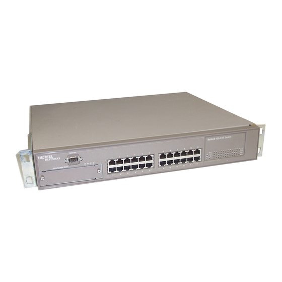
Physical Description There are three versions of the BayStack 450 switch: the BayStack 450-24T switch, the BayStack 450-12T switch, and the BayStack 450-12F switch (Figure 1-1). BayStack 450-24T BayStack 450-12T BayStack 450-12F Figure 1-1. Front Panel Figure 1-2 shows the front-panel configurations for the three BayStack 450 switch models. - Page 35 14 15 = Comm Port = Uplink/Expansion Module slot = Port connectors = LED display panel Figure 1-2. BayStack 450 Switch Front Panels 309978-D Rev 01 BayStack 450-24T BayStack 450-12T BayStack 450-12F 10/100 Activity Status Dwn 10/100 RPSU Base Activity...
-
Page 36: Comm Port
Dependent Adapters” for more information about MDA types available from Nortel Networks). 10BASE-T/100BASE-TX Ports Your BayStack 450-24T and BayStack 450-12T switches use 10BASE-T/100BASE-TX RJ-45 (8-pin modular) port connectors. Note: The RJ-45 port connectors on BayStack 450 switches manufactured prior to December 1998 are numbered 1 to 12 and 13 to 24, in succession from left to right. -
Page 37: 100Base-Fx Mt-Rj Ports
(see “MDI and MDI-X Devices” on page F-2). Your BayStack 450-24T and BayStack 450-12T switches use autosensing ports that are designed to operate at 10 Mb/s or at 100 Mb/s, depending on the connecting device. -
Page 38: Led Display Panel
LED Display Panel Figures 1-3 and 1-4 show the BayStack 450-24T, BayStack 450-12T, and the BayStack 450-12F LED display panels. See Table 1-1 for a description of the LEDs. BayStack Status Dwn RPSU Base BayStack Status Dwn RPSU Base Figure 1-3. - Page 39 The switch failed the self-test. The switch is connected to the HRPSU and can receive power if needed. The switch is not connected to the HRPSU or HRPSU is not supplying power. The switch is in standalone mode. The switch is connected to the upstream unit’s Cascade A In connector.
-
Page 40: Table 1-1. Baystack 450 Switch Led Descriptions
ID (Renumber Stack Unit table full). The unit is on the ring but cannot participate in the stack configuration. The switch is configured as the stack base unit. The switch is not configured as the stack base unit (or is in standalone mode). Blinking Stack configuration error: Indicates that multiple base units or no base units are configured in the stack. - Page 41 Duplex status Green Activity Port activity Green 309978-D Rev 01 BayStack 450 Switch LED Descriptions State Meaning The corresponding port is set to operate at 100 Mb/s and the link is good. Blinking The corresponding port has been disabled by software.
-
Page 42: Back Panel
Back Panel The BayStack 450 switch back-panel components (Figure 1-5) are the same for all switch versions. Descriptions of the back-panel components follow the figure. = Cooling fans (not shown) = AC power receptacle = Cascade Module Slot = RPSU connector Figure 1-5. - Page 43 Table 1-2. Country/Plug description Continental Europe: • CEE7 standard VII male plug • Harmonized cord (HAR marking on the outside of the cord jacket to comply with the CENELEC Harmonized Document HD-21) U.S./Canada/Japan: • NEMA5-15P male plug • UL recognized (UL stamped on cord jacket) •...
-
Page 44: Redundant Power Supply Unit (Rpsu) Connector
BayStack 450 switches in the event that any of the switch power supplies fail. Nortel Networks provides the HRPSU power rack (Order No. AA0002001) with four slots for power supply modules (Order No. AA0005003). Each HRPSU can support up to four BayStack 450 switches. -
Page 45: Cooling Fans
The variable-speed cooling fans (not shown) are located on one side of the BayStack 450 switch to provide cooling for the internal components. When you install the switch, be sure to allow enough space on both sides of the switch for adequate air flow. - Page 46 IEEE 802.3u-compliant autonegotiation ports, with four modes: -- 10BASE-T half-duplex -- 10BASE-T full-duplex -- 100BASE-TX half-duplex -- 100BASE-TX full-duplex • MultiLink Trunking, supporting: -- Switch-to-switch trunks -- Switch-to-server trunks • Port mirroring (conversation steering) -- Port-based -- MAC address-based •...
- Page 47 • Security: -- MAC address-based security: Allows you to limit access to the switch based on MAC addresses. -- EAPOL-based security: EAP over LANs (EAPOL) security allows you to limit access to the switch based on the Extensible Authentication Protocol (EAP).
-
Page 48: Snmp Support
The following two sections describe the SNMP support for the BayStack 450 switch. MIBs The BayStack 450 switch supports an SNMP agent with industry-standard MIBs, as well as private MIB extensions, which ensures compatibility with existing network management tools. The BayStack 450 switch supports the MIB-II (RFC 1213), the Bridge MIB (RFC 1493), and the RMON MIB (RFC 1757), which provide access to detailed management statistics. -
Page 49: Snmp Traps
System wide Security Your BayStack 450 switch security feature can provide four levels of security for your local area network (LAN): • “MAC Address-Based Security” (page 1-20) -- Limits access to the switch based on allowed source MAC addresses. - Page 50 Figure 1-6. BayStack 450 Switch Security Feature Example In this configuration example, the following security measures are implemented: • The switch The switch is located in a locked closet, accessible only by authorized Technical Services personnel. 1-18 To Network Center Teachers’...
- Page 51 PC into the wall jack. The printer is assigned as a single station and is allowed full bandwidth on that switch port. It is assumed that all PCs are password protected and that the classrooms and offices are physically secured.
-
Page 52: Mac Address-Based Security
The MAC address-based security feature is based on Nortel Networks BaySecure ™ Ethernet networks from unauthorized surveillance and intrusion. To learn more about Nortel Networks BaySecure LAN Access for Ethernet, refer to the Bay Networks Guide to Implementing BaySecure LAN Access for Ethernet (Part number 345-1106A). 1-20... -
Page 53: Eapol-Based Security
(EAP), as described in the IEEE Draft P802.1X, to allow you to set up network access control on internal LANs. EAP allows the exchange of authentication information between any end station or server connected to the switch and an authentication server (such as a RADIUS server). This feature operates in conjunction with a RADIUS-based server to extend the benefits of remote authentication to internal LAN clients (see “RADIUS-Based Security”... - Page 54 The switch relays the EAPOL packet to the RADIUS server (4). If the RADIUS server validates the password (5), the new client is allowed access to the switch and the network (6). New client PC Figure 1-7. New client PC Figure 1-8.
-
Page 55: Overview And Terms
Some components of EAPOL-based security are: • Supplicant -- the entity that the Authenticator is authorizing. The supplicant can be any end station or server that is connected to the switch. In the preceding example, the supplicant is the new client PC. •... -
Page 56: Dynamic Vlan Assignment
Port Priority When the EAPOL-based security is disabled on a port that was previously authorized, the port’s VLAN configuration values are restored directly from the switch’s nonvolatile random access memory (NVRAM). The following exceptions apply to dynamic VLAN assignments: •... -
Page 57: Setting Up The Authentication Server
VLAN) • Port Priority (Vendor-Specific) Attributes -- Vendor Id: value 562, Nortel Networks vendor ID -- Attribute Number: value 1, Port Priority -- Attribute Value: value 0 (zero) to 7 (this value is used to indicate the port... -
Page 58: Authentication Process
The flowcharts shown in Figures 1-9 and 1-10 describe the authentication process. Login screen Authentication successful? Authentication server sent VLAN ID? Port-based Switch sets VLAN ID and PVID values to preconfigured values stored in the Authentication server. Figure 1-9. 1-26 See System Administrator. Switch restores VLAN ID and PVID Does... -
Page 59: System Requirements
• Microsoft Windows XP Client (or any generic client that supports EAPOL) You must configure your BayStack 350/410-24T/450 switches and Business Policy Switch 2000 switches for port-based VLANs and EAPOL security (see the appropriate switch User’s Guide). 309978-D Rev 01 Switch restores Port Priority value from NVRAM. -
Page 60: Configuration Rules
EAP) as the primary RADIUS server for these devices. You can manage network access to your switch or stack using the CI menus and screens as described in Chapter 3, “Using the Console Interface,” or you can use the Optivity SecureLAN application (refer to Managing Network Access with Optivity SecureLAN [Part number 312688-A]). -
Page 61: Snmp-Based Security
To provide each user with appropriate levels of access to the switch, set the following username attributes on your RADIUS server: • Read-write access -- Set the Service-Type field value to Administrative. • Read-only access -- Set the Service-Type field value to NAS-Prompt. -
Page 62: Configuration Parameters
IP address to the switch or stack, depending on the mode of operation (see “Initial Setup” on page 2-17). You can also set up a BootP server to recognize the BayStack 450 switch BootP requests (see “BootP Automatic IP Configuration/MAC Address” following this section). -
Page 63: Bootp Automatic Ip Configuration/Mac Address
IP address, subnet mask, IP address of the default router (default gateway), and software image file name. When the switch is participating in a stack configuration, a Stack MAC address is assigned automatically during the stack initialization. The base unit’s MAC address, with an offset, is used for the Stack MAC address. -
Page 64: Network Configurations
(PCs), and servers to each other by connecting these devices directly to the switch, through a shared media hub that is connected to the switch, or by creating a virtual LAN (VLAN) through the switch. This section provides five network configuration examples using BayStack 450 switches: •... -
Page 65: Desktop Switch Application
Desktop Switch Application Figure 1-11 shows a BayStack 450-24T switch used as a desktop switch, where desktop workstations are connected directly to switch ports. This configuration provides dedicated 100 Mb/s connections to the network center, to the server, and up to 26 users. This configuration uses the optional 400-4TX MDA (10BASE-T/100BASE-TX MDA). -
Page 66: Segment Switch Application
Segment Switch Application Figure 1-12 shows a BayStack 450-24T switch used as a segment switch to alleviate user contention for bandwidth and eliminate server and network bottlenecks. Before segmentation, 88 users had a total bandwidth of only 10 Mb/s available. After segmentation, 92 users have 40 Mb/s, four times the previous bandwidth, while adding 22 dedicated 100 Mb/s connections. -
Page 67: High-Density Switched Workgroup Application
Mb/s connections to the BayStack 450 switch, a 100BASE-TX hub, and a 100 Mb/s server and 10 Mb/s connections to DTE (data terminal equipment). See the Nortel Networks library Web page: www25.nortelnetworks.com/library/ for online documentation about the Nortel Networks Accelar 1100 switch and the BayStack 303 and 304 switches. BayStack 450-24T... -
Page 68: Atm Application
MDA. In this example, the BayStack 450-2M3/2S3 MDAs provide asynchronous transfer mode (ATM) connections to a Nortel Networks Centillion Clients (PCs) that are connected to S1 can communicate with clients connected to S2, provided that the VLANs (with their respective client members) are mapped onto the same ELANs, as shown. -
Page 69: Setting Up An Atm Configuration
Appendix E, “Quick Steps to Features,” provides flowcharts that you can use as quick configuration guides for the BayStack 450 switch features. See the Nortel Networks library Web page: www25.nortelnetworks.com/library/ for online documentation about the Nortel Networks Centillion 100 switch. 309978-D Rev 01 1-37... -
Page 70: Fail-Safe Stack Application
If any unit in the stack fails, the stack remains operational. As shown in Figure 1-15, the Accelar 1100 switch is used as a backbone switch, connecting to the BayStack 450 switch with two optional gigabit (1000BASE-SX) MDAs that are MultiLink Trunked (T1) for maximum bandwidth. -
Page 71: Stack Operation
BayStack 410-24T BayStack 410-24T BayStack 410-24T BayStack 410-24T Figure 1-16. The terms “Nortel Networks Business Policy Switch 2000” and “Business Policy Switch” are used synonymously in this guide. 309978-D Rev 01 A Business Policy Switch must A Business Policy Switch must... - Page 72 Note: If the ISVNs are different, only the units that have the same ISVN as the base unit will form a stack. You can verify your switch software version and ISVN in the sysDescr field of the System Characteristics screen (see “System Characteristics” on page 3-16).
-
Page 73: Baystack 400-St1 Cascade Module
Figure 1-18). Unit Select Switch The Unit Select switch (up = Base) determines the base unit for the stack configuration (see “Base Unit” on page 1-43). The Unit Select switch status is displayed on the BayStack 450 LED display panel. When the Unit Select switch is in the Base (up) position, all other Unit Select switches in the stack configuration must be set to Off (down). -
Page 74: Cascade A In Connector
Cascade A In Connector Provides an attachment point for accepting a cascade cable connection from an adjacent unit in the stack. A return cable from this unit’s Cascade A Out connector to the adjacent unit’s Cascade A In connector completes the stack connection (see the example shown in Figure 1-18). -
Page 75: Base Unit
Business Policy Switch 2000 units, a Business Policy Switch 2000 must be configured as the base unit. Note: If you do not designate a Business Policy Switch 2000 as the base unit of a mixed stack configuration, the stack configuration will not operate. - Page 76 (assign another Business Policy Switch 2000, if available) until the failed unit is repaired or replaced. Set the Unit Select switch on the temporary base unit to Base (up = Base) to reassign it as the new base unit.
-
Page 77: Stack Configurations
As shown in Figure 1-19, the cascade connectors and cables on the 400-ST1 front panel provide the ability to stack up to eight supported switches. With BayStack 400-4TX MDAs installed in each switch, the stack can accommodate a maximum of 224 switch ports. -
Page 78: Stack Up Configurations
Stack Up Configurations In Figure 1-19, data flows from the base unit (unit 1) to the next switch, which is assigned as unit 2, and continues until the last switch in the stack is assigned as unit 8. The physical order of the switches is from bottom to top (unit 1 to unit 8). -
Page 79: Figure 1-20. Stack Down Configuration Example
Certain network management station (NMS) applications assume a stack down configuration for the graphical user interface (GUI) that represents the stack (see Figure 1-20). For this reason, Nortel Networks recommends that you always configure the top unit in the stack as the base unit. -
Page 80: Redundant Cascade Stacking Feature
• You can downline upgrade the entire stack from any switch in the stack. • You can access and manage the stack using a TELNET connection or any generic SNMP management tool through any switch port that is part of the stack configuration. -
Page 81: Virtual Local Area Networks (Vlans)
Unit 1 Unit 2 Unit 3 Unit 4 Unit 5 1 = Base unit 2 = Last unit 3 = Cascade cable (PN 303978-A) 4 = Cascade max-return cable (PN 303979-A) Figure 1-21. Virtual Local Area Networks (VLANs) In a traditional shared-media network, traffic generated by a station is propagated to all other stations on the local segment. -
Page 82: Supported Vlan Types
(Figure 1-22). With network segmentation, each switch port connects to a segment that is a single broadcast domain. When a switch port is configured to be a member of a VLAN, it is added to a group of ports (workgroup) that belong to one broadcast domain. -
Page 83: Figure 1-22. Port-Based Vlan Example
BayStack 450 10/100/1000 Series Switches The BayStack 450 switch allows you to assign ports to VLANs using the console, TELNET, or any generic SNMP-based network management software. You can assign different ports (and therefore the devices attached to these ports) to different broadcast domains. -
Page 84: Ieee 802.1Q Tagging
Tagged frame -- the 32-bit field (VLAN tag) in the frame header that identifies the frame as belonging to a specific VLAN. Untagged frames are marked (tagged) with this classification as they leave the switch through a port that is configured as a tagged port. - Page 85 • Filtering database identifier (FID) -- the specific filtering/forwarding database within the BayStack 450 switch that is assigned to each VLAN. The current version of software assigns all VLANs to the same FID. This is referred to as Shared VLAN Learning in the IEEE 802.1Q specification.
- Page 86 When configuring VLANs, you configure the switch ports as tagged or untagged members of specific VLANs (see Figures 1-24 to 1-29). In Figure 1-24, untagged incoming packets are assigned directly to VLAN 2 (PVID = 2). Port 5 is configured as a tagged member of VLAN 2, and port 7 is configured as an untagged member of VLAN 2.
-
Page 87: Figure 1-25. 802.1Q Tagging (After Port-Based Vlan Assignment)
As shown in Figure 1-25, the untagged packet is marked (tagged) as it leaves the switch through port 5, which is configured as a tagged member of VLAN 2. The untagged packet remains unchanged as it leaves the switch through port 7, which is configured as an untagged member of VLAN 2. -
Page 88: Figure 1-27. 802.1Q Tagging (After Protocol-Based Vlan Assignment)
As shown in Figure 1-27, the untagged packet is marked (tagged) as it leaves the switch through port 5, which is configured as a tagged member of VLAN 3. The untagged packet remains unchanged as it leaves the switch through port 7, which is configured as an untagged member of VLAN 3. -
Page 89: Figure 1-28. 802.1Q Tag Assignment
As shown in Figure 1-29, the tagged packet remains unchanged as it leaves the switch through port 5, which is configured as a tagged member of VLAN 2. However, the tagged packet is stripped (untagged) as it leaves the switch through port 7, which is configured as an untagged member of VLAN 2. -
Page 90: Vlans Spanning Multiple Switches
VLANs Spanning Multiple Switches You can use VLANs to segment a network within a switch. When connecting multiple switches, it is possible to connect users of one VLAN with users of that same VLAN in another switch. However, the configuration guidelines depend on whether both switches support 802.1Q tagging. -
Page 91: Vlans Spanning Multiple Untagged Switches
VLANs Spanning Multiple Untagged Switches Figure 1-31 shows VLANs spanning multiple untagged switches. In this configuration switch S2 does not support 802.1Q tagging and you must use a single switch port on each switch for each VLAN. For this configuration to work properly, you must set spanning tree participation to Disabled (the STP is not supported across multiple LANs). - Page 92 Because the other link connecting VLAN 2 is in the Blocking state, stations on VLAN 2 in switch S1 cannot communicate with stations in VLAN 2 on switch S2. With multiple links, only one link will be in the Forwarding state.
-
Page 93: Shared Servers
VLAN 2 (PVID=2) VLAN 3 (PVID=3) Figure 1-33. In the above configuration, all of the switch ports are set to participate as VLAN port members. This allows the switch to establish the appropriate broadcast domains within the switch (see Figure 1-34). - Page 94 VLAN 3 broadcast domain shown in Figure 1-34. 1-62 VLAN 3 VLAN 2 Port 4 Port 10 Port 8 PVID = 3 VLAN Broadcast Domains Within the Switch VLAN 1 Port 6 Port 11 PVID = 1 BS45019A 309978-D Rev 01...
-
Page 95: Figure 1-35. Default Vlan Configuration Screen Example
Default VLAN Configuration Screen Example The VLAN Configuration screen settings shown in Figure 1-35 are default settings with all switch ports classified as untagged members of VLAN 1. Figure 1-36 shows the VLAN Configuration screen after it is configured to support the VLAN 3 broadcast domain shown in Figure 1-34 (VLAN Name is optional). -
Page 96: Figure 1-36. Vlan Configuration Screen Example
Ports 2, 4, 6, 8, 10, and 11 are now untagged members of VLAN 3 as shown in Figure 1-34 on page 1-62. Create VLAN: Delete VLAN: VLAN Name: [ Glenn’s VLAN ] Management VLAN: [ Yes ] Port Membership 7-12 ------ ------... -
Page 97: Figure 1-37. Default Vlan Port Configuration Screen Example
Unit: Port: Filter Tagged Frames: Filter Untagged Frames: Filter Unregistered Frames: Port Name: PVID: Port Priority: Tagging: AutoPVID (all ports): Use space bar to display choices, press <Return> or <Enter> to select choice. Press Ctrl-R to return to previous menu. Figure 1-37. -
Page 98: Figure 1-38. Vlan Port Configuration Screen Example
Unit: Port: Filter Tagged Frames: Filter Untagged Frames: Filter Unregistered Frames: Port Name: PVID: Port Priority: Tagging: AutoPVID (all ports): Use space bar to display choices, press <Return> or <Enter> to select choice. Press Ctrl-R to return to previous menu. Figure 1-38. -
Page 99: Vlan Workgroup Summary
VLAN Workgroup Summary This section summarizes the VLAN workgroup examples discussed in the previous sections of this chapter. As shown in Figure 1-39, switch S1 (a BayStack 450 switch) is configured with multiple VLANs: Non-802.1Q tagging switch Untagged ports (STP disabled) -
Page 100: Vlan Configuration Rules
Because S4 does not support 802.1Q tagging, a single switch port on each switch must be used for each VLAN (see “VLANs Spanning Multiple Untagged Switches” on page 1-59). The connection to S2 requires only one link between the switches because S1 and S2 are both BayStack 450 switches that support 802.1Q tagging (see “VLANs... -
Page 101: Igmp Snooping
IP multicast router. After the pathway is established, the BayStack 450 switch blocks the IP multicast stream from exiting any other port that does not connect to another host member, thus conserving bandwidth. - Page 102 Figure 1-40. IP Multicast Propagation With IGMP Routing The BayStack 450 switch can automatically set up IP multicast filters so the IP multicast traffic is directed only to the participating end nodes (see Figure 1-41). In Figure 1-41, switches S1 to S4 represent a LAN connected to an IP multicast router.
- Page 103 Figure 1-41. BayStack 450 Switch Filtering IP Multicast Streams (1 of 2) Switch S1 treats the consolidated proxy reports from S2 and S4 as if they were reports from any client connected to its ports, and generates a consolidated proxy report to the designated router.
- Page 104 Figure 1-42. BayStack 450 Switch Filtering IP Multicast Streams (2 of 2) The consolidated proxy report generated by the switch remains transparent to layer 3 of the International Organization for Standardization, Open Systems Interconnection (ISO/OSI) model. (The switch IP address and MAC address are not part of proxy report generation.) The last reporting IGMP group member in...
-
Page 105: Igmp Snooping Configuration Rules
IGMP Snooping Configuration Rules The IGMP snooping feature operates according to specific configuration rules. When configuring your switch for IGMP snooping, consider the following rules that determine how the configuration reacts in any network topology: • A port that is currently configured for EAPOL-based security cannot be configured as a static router port. -
Page 106: Ieee 802.1P Prioritizing
Figure 1-43. Prioritizing Packets The newly tagged frame is read within the switch and sent to the port’s high or low transmit queue for disposition (see Figure 1-44). The port transmit queue example shown in Figure 1-44 applies to all ports on the BayStack 450 switch. - Page 107 User priority Figure 1-44. As shown in Figure 1-44, the switch provides two transmission queues, High and Low, for any given port. Frames are assigned to one of these queues on the basis of the user_priority value, using a traffic class table. This table is managed by using the Traffic Class Configuration screen (Figure 1-45).
-
Page 108: Figure 1-45. Default Traffic Class Configuration Screen Example
To configure the port priority level, follow these steps: Determine the priority level you want to assign to the switch port. User priority levels are assigned default settings in all BayStack 450 switches. The range is from 0 to 7. The traffic class table can be modified; therefore, view the settings shown in the Traffic Class Configuration screen before setting the port priority in the VLAN Port Configuration screen. -
Page 109: Figure 1-46. Setting Port Priority Example
Select a priority level from the range shown in the Traffic Class Configuration screen (or modify the Traffic Class parameters to suit your needs). Assign the priority level to ports using the VLAN Port Configuration screen: Press [Ctrl]-R to return to the VLAN Configuration Menu. From the VLAN Configuration Menu, select VLAN Port Configuration (or press c). -
Page 110: Multilink Trunks
MultiLink Trunks A MultiLink Trunk (MLT) link to another switch or server. This can increase the aggregate throughput of the interconnection between devices as much as 800 Mb/s in full-duplex mode (up to 8000 Mb/s with optional gigabit MDA ports). You can configure up to six MultiLink Trunks. -
Page 111: Client/Server Configuration Using Multilink Trunks
You can configure each of the trunks shown in Figure 1-47 with up to four switch ports to provide up to 800 Mb/s aggregate bandwidth through each trunk, in full-duplex mode. As shown in this example, when traffic between switch-to-switch connections approaches single port bandwidth limitations, creating a MultiLink Trunk can supply the additional bandwidth required to improve the performance. -
Page 112: Figure 1-49. Client/Server Configuration Example
Clients accessing data from the servers (FS1 and FS2) are provided with maximized bandwidth through trunks T1, T2, T3, T4, and T5. Trunk members (the ports making up each trunk) do not have to be consecutive switch ports; you can select ports randomly, as shown by T5. -
Page 113: Trunk Configuration Screen Examples
1-93, and “MultiLink Trunk Configuration” on page 3-64 for more information. Trunk Configuration Screen for Switch S1 Switch S1 is set up with five trunk configurations: T1, T2, T3, T4, and T5. Setting Up the Trunk Configuration for S1: To set up the trunk configuration, choose MultiLink Trunk Configuration (or press t) from the MultiLink Trunk Configuration Menu screen (Figure 1-50). -
Page 114: Figure 1-51. Multilink Trunk Configuration Screen For Switch S
MultiLink Trunk Configuration Screen for Switch S1 Switch S1 is configured as follows: • Trunk (read only) indicates the trunks (1 to 6) that correspond to the switch ports specified in the Trunk Members fields. • Trunk Members (Unit/Port) indicates the ports that can be configured, in... - Page 115 Trunk Name indicates optional fields for assigning names to the corresponding configured trunks. The names chosen for this example provide meaningful information to the user of this switch (for example, S1:T1 to FS2 indicates that trunk 1, in switch S1, connects to file server 2). 309978-D Rev 01...
-
Page 116: Trunk Configuration Screen For Switch S2
Trunk Configuration Screen for Switch S2 As shown in Figure 1-49 on page 1-80, switch S2 is set up with two trunk configurations (T2 and T3). Both trunks connect directly to switch S1. As in the previous screen examples, to set up a trunk configuration, choose MultiLink Trunk Configuration from the MultiLink Trunk Configuration Menu. - Page 117 Trunk Name indicates optional fields for assigning names to the corresponding configured trunks. The names chosen for this example provide meaningful information to the user of this switch (for example, S2:T2 to S1 indicates that trunk 1, in switch S2, connects to switch 1). 309978-D Rev 01...
-
Page 118: Trunk Configuration Screen For Switch S3
Trunk Configuration Screen for Switch S3 As shown in Figure 1-49 on page 1-80, switch S3 is set up with one trunk configuration (T4). This trunk connects directly to switch S1. As in the previous screen examples, to set up an interswitch trunk configuration, choose MultiLink Trunk Configuration from the MultiLink Trunk Configuration Menu. - Page 119 Trunk Name indicates optional fields for assigning names to the corresponding configured trunks. The names chosen for this example provide meaningful information to the user of this switch (for example, S3:T4 to S1 indicates that trunk 1, in switch S3, connects to switch 1). 309978-D Rev 01...
-
Page 120: Trunk Configuration Screen For Switch S4
Trunk Configuration Screen for Switch S4 As shown in Figure 1-49, switch S4 is set up with one trunk configuration (T5). This trunk connects directly to switch S1. As in the previous screen examples, to set up a trunk configuration, choose MultiLink Trunk Configuration from the MultiLink Trunk Configuration Menu. - Page 121 Trunk Name indicates optional fields for assigning names to the corresponding configured trunks. The names chosen for this example provide meaningful information to the user (for example, S4:T5 to S1 indicates that trunk 1, in switch S4, connects to switch 1). 309978-D Rev 01...
-
Page 122: Before Configuring Trunks
Before Configuring Trunks When you create and enable a trunk, the trunk members (switch ports) take on certain settings necessary for correct operation of the MultiLink Trunking feature. Before configuring your MultiLink Trunk, you must consider these settings, along with specific configuration rules, as follows: Read the configuration rules provided in the next section, “MultiLink... - Page 123 • All trunk members must have the same VLAN configuration before the Trunk Configuration screen’s Trunk Status field can be set to Enabled (see “VLAN Configuration Menu” on page 3-44). • When an active port is configured in a trunk, the port becomes a trunk member when you set the Trunk Status field to Enabled.
-
Page 124: How The Multilink Trunk Reacts To Losing Distributed Trunk Members
Spanning Tree Configuration • Port Mirroring Configuration • Port Configuration • IGMP Configuration • Rate Limiting Configuration 1-92 BayStack 450-24T Switches 450-1SR MDA 450-1SR MDA 450-1SR MDA 450-1SR MDA CPU PS1 PS2 FAN Unit 1 Unit 2 Unit 3 Unit 4... -
Page 125: Spanning Tree Considerations For Multilink Trunks
Spanning Tree Considerations for MultiLink Trunks The spanning tree Path Cost parameter is recalculated based on the aggregate bandwidth of the trunk. For example, Figure 1-56 shows a four-port trunk (T1) with two port members operating at 100 Mb/s and two at 10 Mb/s. Trunk T1 provides an aggregate bandwidth of 220 Mb/s. -
Page 126: Figure 1-57. Example 1: Correctly Configured Trunk
The switch can also detect trunk member ports that are physically misconfigured. For example, in Figure 1-57, trunk member ports 2, 4, and 6 of switch S1 are configured correctly to trunk member ports 7, 9, and 11 of switch S2. The Spanning Tree Port Configuration screen for each switch shows the port state field for each port in the Forwarding state. -
Page 127: Figure 1-58. Example 2: Detecting A Misconfigured Port
BayStack 450 10/100/1000 Series Switches If switch S2’s trunk member port 11 is physically disconnected and then reconnected to port 13, the Spanning Tree Port Configuration screen for switch S1 changes to show port 6 in the Blocking state (Figure 1-58). -
Page 128: Additional Tips About The Multilink Trunking Feature
Additional Tips About the MultiLink Trunking Feature When you create a MultiLink Trunk, the individual trunk members (the specific ports that make up the trunk) logically connect and react as a single entity. For example, if you change spanning tree parameters for any trunk member, the spanning tree parameters for all trunk members change. -
Page 129: Port Mirroring (Conversation Steering)
Port Mirroring (Conversation Steering) The port mirroring feature (sometimes referred to as conversation steering) allows you to designate a single switch port as a traffic monitor for up to two specified ports or two media access control (MAC) addresses. You can designate one of your switch ports to monitor traffic on any two specified switch ports (port-based) or to monitor traffic to or from any two specified addresses that the switch has learned (address-based). -
Page 130: Port-Based Mirroring Configuration
Figure 1-59 shows an example of a port-based mirroring configuration where port 23 is designated as the monitor port for ports 24 and 25 of switch S1. Although this example shows ports 24 and 25 monitored by the monitor port (port 23), any of the trunk members of T1 and T2 can also be monitored. - Page 131 As shown in the Port Mirroring Configuration screen example (Figure 1-60), port 23 is designated as the Monitor Port for ports 24 and 25 in switch S1. Note: The Unit value (in the Unit/Port field) cannot be configured when the switch is operating standalone.
-
Page 132: Address-Based Mirroring Configuration
Port Mirroring Port-Based Screen Example Address-Based Mirroring Configuration Figure 1-61 shows an example of an address-based mirroring configuration where port 23, the designated monitor port for switch S1, is monitoring traffic occurring between address A and address B. 1-100 Port Mirroring Configuration ->... - Page 133 Figure 1-61. In this configuration, the designated monitor port (port 23) can be set to monitor traffic in any of the following modes: • Monitor all traffic address A transmits to any address. • Monitor all traffic address A receives from any address. •...
-
Page 134: Figure 1-62. Port Mirroring Address-Based Screen Example
In this example, port 23 becomes the designated Monitor Port for switch S1 when you press [Enter] in response to the [Yes] screen prompt. Note: The screen data displayed at the bottom of the screen changes to show the new currently active port mirroring configuration after you press [Enter]. -
Page 135: Port Mirroring Configuration Rules
When you configure a port as a monitor port, the port is automatically disabled from participating in the spanning tree. When you reconfigure the port as a standard switch port (no longer a monitor port), the port is enabled for spanning tree participation. -
Page 137: Installing The Baystack 450 Switch
Note: Be sure that the supplied AC power cord matches the requirements for your region; see “AC Power Receptacle” on page 1-10. Install the BayStack 450 switch in a ventilated area that is dust free and away from heat vents, warm air exhaust from other equipment, and direct sunlight. Avoid proximity to large electric motors or other electromagnetic equipment. -
Page 138: Figure 2-1. Package Contents
If any items are missing or damaged, contact the sales agent or the customer service representative from whom you purchased the BayStack 450 switch. BayStack 450 switch... -
Page 139: Installation Procedure
This section provides the requirements and instructions for installing the BayStack 450 switch on a flat surface or in a standard 19-inch utility rack. If you install the switch in a rack, ground the rack to the same grounding electrode used by the power service in the area. -
Page 140: Installing The Baystack 450 Switch In A Rack
The BayStack 450 switch can be mounted onto any appropriate flat, level surface that can safely support the weight of the switch and its attached cables, as long as there is adequate space around the unit for ventilation and access to cable connectors. -
Page 141: Figure 2-2. Positioning The Chassis In The Rack
1 ohm of resistance from the rack to the grounding electrode. To install the BayStack 450 switch in a rack, follow these steps: Determine how far you want the switch to protrude in front of the rack. 1 = Flush with rack 2 = Extended from rack Figure 2-2. - Page 142 You can install the switch flush to the rack or extended from the rack, depending on the orientation of the mounting brackets. Using a Phillips screwdriver, attach a mounting bracket to each side of the switch using the supplied screws (Figure 2-3).
-
Page 143: Attaching Devices To The Baystack 450 Switch
(MDAs). The MDAs support a range of media types (see Appendix C, “Media Dependent Adapters,” for more information about MDA types available from Nortel Networks). Refer to the documentation that came with your specific MDA for information about its cabling and LED indications. -
Page 144: Connecting The 10Base-T/100Base-Tx Ports
MDI-X ports. As in conventional Ethernet repeater hubs, these ports connect via straight-through cables to the network interface card (NIC) in a node or server. When connecting to an Ethernet hub or to another switch, you must use a crossover cable. See Appendix F, “Connectors and Pin Assignments,” for more information. -
Page 145: Connecting Fiber Optic Ports
Connecting Fiber Optic Ports Connect devices to the fiber optic ports as shown in Figure 2-6. The BayStack 450-12F switch and the 400-4FX MDA are 100BASE-FX devices. Both products use MT-RJ port connectors with 62.5/125-micron multimode fiber optic cable. The 400-2FX MDA is also a 100BASE-FX device but uses standard SC port connectors with 62.5/125 micron multimode fiber optic cable. -
Page 146: Console/Comm Port
You can also connect this port to an external modem to enable remote dial-in management of the switch. The port is a male DB-9 connector, implemented as a data communication equipment (DCE) connection. -
Page 147: Connecting A Terminal To The Console/Comm Port
RS-232 cable. Connect the female connector of the RS-232 cable directly to the Console/Comm Port on the switch, and then tighten the captive retaining screws (see Figure 2-7). Connect the other end of the cable to a terminal or the serial connector of a personal computer running communications software. -
Page 148: Connecting Power
Connecting Power The BayStack 450 switch does not have a power on/off switch. When you connect the AC power cord to a suitable AC power outlet, the switch powers up immediately. Warning: Removal of the power cord is the only way to turn off power to this device. - Page 149 Plug the other end of the AC power cord into the grounded AC power outlet (Figure 2-9). Figure 2-9. See the next section, “Verifying the Installation.” 309978-D Rev 01 Cascade Module BS45039A BayStack 450 Switch AC Power Receptacle 612FA Grounded AC Power Outlet 2-13...
-
Page 150: Verifying The Installation
Verifying the Installation When power is applied to the switch, power-on self-tests run. You can verify proper operation of the BayStack 450 switch by observing the front-panel LEDs or by viewing the self-test results as displayed in the BayStack 450 switch Self-Test screen. -
Page 151: Verifying The Installation Using The Self-Test Screen
Self-Test screen). The results of the self-test are displayed briefly (5 or 10 seconds) on the Self-Test screen, which is followed by the Nortel Networks Logo screen (Figure 2-12). Note: The Self-Test screen remains displayed only if the self-test detects a fatal error. -
Page 152: Figure 2-12. Nortel Networks Logo Screen
Enter Ctrl-Y to begin. Figure 2-12. Nortel Networks Logo Screen Note: The Nortel Networks logo screen for your switch will display the correct model number and the current hardware, firmware, software, and ISVN versions. Upon successful completion of the power-up self-tests, the switch is ready for normal operation. -
Page 153: Initial Setup
Standalone Switch Setup For the initial setup of a standalone switch, you need to enter the IP address of the switch, the subnet mask, and the gateway address (see Chapter 3, “Using the Console Interface,”... -
Page 154: Figure 2-13. Main Menu For Standalone Switch
This selection displays the IP Configuration/Setup screen (Figure 2-14). Note: The default management VLAN (IP interface) for the BayStack 450 switch is VLAN 1. However, you can specify which VLAN you want to be the management VLAN (see “VLAN Configuration” on page 3-46). -
Page 155: Figure 2-14. Ip Configuration/Setup Screen (Standalone Switch)
Press Ctrl-R to return to previous menu. Figure 2-14. IP Configuration/Setup Screen (Standalone Switch) Enter the IP address of the switch in the In-Band IP Address field, and then press [Enter]. Note: When you enter the IP address in the In-Band Stack/Switch IP... -
Page 156: Stack Setup
(see Chapter 3, “Using the Console Interface,” for more information about configuring your BayStack 450 switch). To set the stack IP address, subnet mask, and gateway address for the switch, follow these steps: Note: Unless otherwise specified, the terms “switch” and “unit” are used interchangeably in this guide. -
Page 157: Figure 2-15. Main Menu (Standalone Switch Example)
Main Menu (Standalone Switch Example) Use arrow keys to highlight option, press <Return> or <Enter> to select option. Figure 2-16. Main Menu (Stack Configuration Example) 309978-D Rev 01 BayStack 450-24T Main Menu IP Configuration/Setup... SNMP Configuration... System Characteristics... Switch Configuration... -
Page 158: Figure 2-17. Ip Configuration/Setup Screen (Stack Configuration)
This selection displays the IP Configuration/Setup screen (Figure 2-17). Note: The default management VLAN (IP interface) for the BayStack 450 switch is VLAN 1. However, you can specify which VLAN you want to be the management VLAN (see “VLAN Configuration” on page 3-46). - Page 159 Enter the IP subnet mask address in the In-Band Subnet Mask field, and then press [Enter]. Enter the default gateway address in the Default Gateway field, and then press [Enter]. See Chapter 3, “Using the Console Interface,” for detailed descriptions of the menus and screens you can use to customize your configuration.
-
Page 161: Using The Console Interface
This chapter describes how to configure and manage the BayStack 450 switch using the menu-driven console interface (CI). This chapter covers the following topics: • “Accessing the CI Menus and Screens” (page 3-2) • “Main Menu” (page 3-5) • “IP Configuration/Setup” (page 3-9) •... -
Page 162: Accessing The Ci Menus And Screens
2000 switches, you must use the Business Policy Switch 2000 switch console interface to configure or monitor your stack. You can also manage the BayStack 450 switch using Nortel Networks Optivity network management software or any generic SNMP-based management software; however, for the switch management function to become fully operational, you must supply certain parameters such as the switch IP address or stack IP address, if configured (see “Initial Setup”... -
Page 163: Navigating The Ci Menus And Screens
The option takes effect immediately after you press [Enter]. Alternatively, you can press the key corresponding to the underlined letter in the option name. For example, to select the Switch Configuration option in the main menu, press the w key. Note that the text characters are not case-sensitive. -
Page 164: Map Of Ci Menus And Screens
Figure 3-1. Map of Console Interface Screens The CI screens for your specific switch model will show the correct model name in the main menu title and the correct number of ports and port types in the Port Configuration screen. -
Page 165: Main Menu
Note: Some menu options shown in this main menu example and in other screen examples in this chapter may not appear on your screen, depending on the switch options installed. However, the full menu options are shown in the screen examples and described in the following sections. -
Page 166: Table 3-1. Console Interface Main Menu Options
ISVN version, and the MAC address. This screen also contains three user-configurable fields: sysContact, sysName, and sysLocation. When the switch is part of a stack configuration, this screen also displays the base unit identification, the number of units configured in the stack, and the local unit stack number. - Page 167 10 user-assigned host IP addresses that are allowed TELNET and SNMP access to the switch. You can set your switch to enable a user at a remote console terminal to communicate with the BayStack 450 switch as if the console terminal were directly connected to it.
- Page 168 Enter Yes to reset the switch to the factory default configuration settings; enter No to abort the option. If the switch is participating in a stack configuration, additional prompts allow you to reset a specific unit in the stack or the entire stack.
-
Page 169: Ip Configuration/Setup
IP Configuration/Setup The IP Configuration/Setup screen (Figure 3-3) allows you to set or modify the BayStack 450 switch IP configuration parameters and to verify a station’s IP address using the ping feature. Data that you enter in the user-configurable fields takes effect as soon as you press [Enter]. -
Page 170: Table 3-2. Ip Configuration/Setup Screen Fields
Address Default Range In-Band Switch The in-band IP address of the BayStack 450 switch. This field is not required for the IP Address operation of the stack. This field cannot use the same IP address used for the stack. Default... -
Page 171: Bootp Request Mode
• BootP Always Note: Whenever the switch is broadcasting BootP requests, the BootP process will time out if a reply is not received within (approximately) 7 minutes. When the process times out, the BootP request mode automatically changes to BootP Disabled mode. -
Page 172: Bootp Disabled
The switch can be managed only by using the in-band IP address set from the console terminal. These actions take effect after the switch is reset or power cycled, even if an IP address is not currently in use. BootP or Last Address Allows the switch to be managed even if a BootP server is not reachable. -
Page 173: Bootp When Needed
BootP When Needed Allows the switch to request an IP address if one has not already been set from the console terminal. When selected, this mode operates as follows: • When the IP data is entered from the console terminal, the data becomes the in-band address of the switch and BootP requests are not broadcast. -
Page 174: Snmp Configuration
SNMP Configuration The SNMP Configuration screen (Figure 3-4) allows you to set or modify the SNMP configuration parameters. Choose SNMP Configuration (or press m) from the main menu to open the SNMP Configuration screen. Read-Only Community String: Read-Write Community String: Trap #1 IP Address: Community String: Trap #2 IP Address:... - Page 175 AutoTopology The Trap IP Address and Community String fields can be set using a MIB table (in a Nortel Networks proprietary MIB). The status of the row in the MIB table can be set to Valid or Ignore. If the row status is set to Ignore, the fields appear to be set when viewed from the console terminal;...
-
Page 176: System Characteristics
00-00-00-00-00-00 Reset Count: Last Reset Type: Power Cycle Power Status: Primary Power Local MDA Type: 1 port 1000Base-LX with LinkSafe, 450-1LR MDA sysDescr: BayStack 450-24T HW:Rev x sysObjectID: 1.3.6.1.4.1.45.3.35.1 sysUpTime: 00:06:26 sysServices: sysContact: [ Mario Lento ] sysName: [ Publications ]... -
Page 177: Table 3-4. System Characteristics Screen Fields
When the unit is part of a stack configuration, the (read-only) field indicates the unit is operational in a stack, and lists the current unit number of this switch. In this example (see Figure 3-5 on page 3-16), the current unit number is Unit 2. - Page 178 System Characteristics Screen Fields Field Description sysObjectID A read-only field that provides a unique identification of the switch, which contains the vendor’s private enterprise number. sysUpTime A read-only field that shows the length of time since the last reset. Note that this field is updated when the screen is redisplayed.
-
Page 179: Switch Configuration
Note: The High Speed Flow Control Configuration option appears only when an optional gigabit MDA is installed. Choose Switch Configuration (or press w) from the main menu to open the Switch Configuration Menu. MAC Address Table MAC Address-Based Security... -
Page 180: Table 3-5. Switch Configuration Menu Options
Displays the Port Mirroring Configuration screen (see “Port Mirroring Configuration” on page 3-71). This screen allows you to designate a single switch port as a traffic monitor for up to two specified ports or addresses. (continued) - Page 181 Yes, to clear all port statistics for all switch ports • No, to abort the option • If the switch is participating in a stack configuration, choose one of the following: • Clear all port statistics for a specific unit in the stack •...
-
Page 182: Mac Address Table
Note: This screen does not refresh dynamically to show new entries. To refresh the screen, press [Ctrl]-R to return to the previous menu. Choose MAC Address Table (or press m) from the Switch Configuration Menu to open the MAC Address Table screen. -
Page 183: Table 3-6. Mac Address Table Screen Fields
MAC Address Table Screen Fields Field Description Aging Time Specifies how long a learned MAC address remains in the switch’s forwarding database. If an entry is inactive for a period of time that exceeds the specified aging time, the address is removed. Default... -
Page 184: Mac Address-Based Security
You can specify a list of up to 448 MAC addresses (within a single standalone switch or within one or more units in a single stacked configuration) that are authorized to access the switch or stack. You can also specify the ports that each MAC address is allowed to access. -
Page 185: Figure 3-8. Mac Address Security Configuration Menu
MAC Address Security Port Configuration... MAC Address Security Port Lists... MAC Address Security Table... Return to Switch Configuration Menu Use arrow keys to highlight option, press <Return> or <Enter> to select option. Press Ctrl-R to return to previous menu. Figure 3-8. -
Page 186: Mac Address Security Configuration
Security Port Configuration” on page 3-30). This screen allows you to specify the MAC addresses that are allowed to access the switch. Return to Switch Exits the MAC Address Security Configuration Menu and displays the Switch Configuration Menu... Configuration Menu. -
Page 187: Figure 3-9. Mac Address Security Configuration Screen
MAC Address Security Configuration MAC Address Security: MAC Address Security SNMP-Locked: Partition Port on Intrusion: DA Filtering on Intrusion: Generate SNMP Trap on Intrusion: MAC Security Table Clear by Ports: [ Learn by Ports: [ Current Learning Mode: Use space bar to display choices, press <Return> or <Enter> to select choice. Press Ctrl-R to return to previous menu. -
Page 188: Table 3-8. Mac Address Security Configuration Screen Fields
Default Range Partition Port on Intrusion This field value determines how the switch reacts to an intrusion event. When an intrusion event is detected (see MAC Address Security field description) the specified port is set to Disabled (partitioned from other switch ports). - Page 189 Range Current Learning Mode Indicates the current learning mode for the switch ports. When this field is set to Enabled, all source MAC addresses of any packets received on the specified port (or ports) are added to the MAC Security Table (maximum of 448 MAC address entries allowed).
-
Page 190: Mac Address Security Port Configuration
MAC Address Security Port Configuration The MAC Address Security Port Configuration screen (Figures 3-10 and 3-11) allows you to enable or disable the MAC address security for each port. Note: You cannot enable MAC address security on a port that is currently configured for EAPOL-based security. -
Page 191: Figure 3-11. Mac Address Security Port Configuration (Screen 2 Of 2)
[ Disabled ] [ Disabled ] [ Disabled ] [ Disabled ] [ Disabled ] Switch [ Enable Stack [ Enable Press Ctrl-P to display choices for ports 1-14. Use space bar to display choices, press <Return> or <Enter> to select choice. -
Page 192: Table 3-9. Mac Address Security Port Configuration Screen Fields
The values that you set in the Switch row will affect all switch ports and, when the switch is part of a stack, the values that you set in the Stack row will affect all ports in the entire stack. -
Page 193: Mac Address Security Port Lists
MAC Address Security Port Lists The MAC Address Security Port Lists screens allow you to create port lists that can be used as allowed source port lists for a specified MAC address in the MAC Address Security Table screen. You can create as many as 32 port lists, using up to five MAC Address Security Port Lists screens (see Figure 3-12). -
Page 194: Figure 3-13. Mac Address Security Port Lists Screen
MAC Address Security Port Lists Entry Port List ----- --------- [ 1/1-7,2/1-7,2/9,3/1-4,4/12 ] [ 2/1-7,2/9,4/3-5 ] [ 1/3,2/7,3/1-4 ] [ 4/12 ] [ 1/NONE,2/NONE,3/NONE,4/NONE ] [ 1/ALL,2/ALL,3/ALL,4/ALL ] [ 3/ALL ] Press Ctrl-N to display next screen. Enter unit/port,"1/NONE","1/ALL","2/3,4/7-9",press <Return> or <Enter> when done Press Ctrl-R to return to previous menu. - Page 195 NONE, or ALL. In a stack configuration, ALL indicates all of the stack ports; in a standalone switch, ALL indicates all of the switch ports. Note: NONE and ALL must be entered in uppercase characters as shown in the screen prompt.
- Page 196 Adding a New Port to an Existing Port Number List: In the example shown in Figure 3-13 on page 3-34, S3 shows the Port List field values as: 1/3,2/7,3/1-4 If you want to add another port (for example, port 2/9) to the existing port number list, you could highlight the field and then type another port list, including the new port number: 1/3,2/7,2/9, 3/1-4 [Enter].
-
Page 197: Mac Address Security Table
MAC Address Security Table The MAC Address Security Table screen allows you to specify the ports that each MAC address is allowed to access. You must also include the MAC addresses of any routers and switches that are connected to any secure ports. There are 16 available MAC Address Security Table screens you can use to create as many as 448 MAC address entries. -
Page 198: Figure 3-15. Mac Address Security Table Screen
Note: The following screen shows an example of typical user input in boldface type. Find an Address: [ 00-00-00-00-00-00 ] MAC Address Allowed Source ----------- -------------- [ 44-33-22-44-55-44 ] [ 22-44-33-55-66-55 ] [ 22-55-33-44-33-22 ] [ 44-22-33-55-44-22 ] [ 22-33-44-55-33-44 ] Press Ctrl-N to display next screen. -
Page 199: Table 3-11. Mac Address Security Table Screen Fields
MAC Address Allows you to specify up to 448 MAC addresses that are authorized to access the switch. You can specify the ports that each MAC address is allowed to access using the Allowed Source field (see next field description). The... -
Page 200: Eapol Security Configuration
RADIUS server documentation; or if you are using the Optivity SecureLAN application, refer to Managing Network Access with Optivity SecureLAN (Part number 312688-A). Note: Do not enable EAPOL security on the switch port that is connected to the RADIUS server. Choose EAPOL Security Configuration (or press e) from the Switch Configuration Menu to display the EAPOL Security Configuration screen. -
Page 201: Figure 3-16. Eapol Security Configuration Screen
Option Description EAPOL Administrative Allows you to enable or disable EAPOL for your switch or stack. When this State field is set to Disabled (the default state), the Operational Status for all of the switch/stack ports is set to Authorized (no security restriction). - Page 202 The ALL value is also useful when you want to apply modified field values to most of, but not all of, your switch’s ports. For example, if you want to apply modified field values to 23 of your switch’s 24 ports, it may be easier to apply the ALL value in the Port field, and then reconfigure the single port back to its original values.
- Page 203 Allows you to specify the time period between any single EAPOL authentication failure and the start of a new EAPOL authentication attempt. Default Range Transmit Period Allows you to specify how long the switch waits for the supplicant to respond to EAP Request/Identity packets. Default Range 309978-D Rev 01...
-
Page 204: Vlan Configuration Menu
Table 3-12. EAPOL Security Configuration Screen Options Option Description Supplicant Timeout Allows you to specify how long the switch waits for the supplicant to respond to all EAP packets, except EAP Request/Identity packets. Default Range Server Timeout Allows you to specify how long the switch waits for the RADIUS server to respond to all EAP packets. -
Page 205: Figure 3-17. Vlan Configuration Menu
Displays the VLAN Port Configuration screen (see “VLAN Port Configuration” Configuration... on page 3-52). This screen allows you to set up a specific switch port. VLAN Display by Port... Displays the VLAN Display by Port screen (see “VLAN Display by Port” on page 3-56). -
Page 206: Vlan Configuration
When you configure ports as VLAN port members, they become part of a set of ports that form a broadcast domain for a specific VLAN. You can assign switch ports, whether standalone or stacked unit ports, as VLAN port members of one or more VLANs. -
Page 207: Figure 3-18. Vlan Configuration Screen
Create VLAN: Delete VLAN: VLAN Name: [ VLAN #1 ] Management VLAN: [ Yes ] 7-12 ------ ------ Unit #1 UUUUUU UUUUUU Unit #2 UUUUUU UUUUUU Unit #3 UUUUUU UUUUUU Unit #4 UUUUUU UUUUUU Enter VLAN Number: 1 KEY: T = Tagged Port Member, U = Untagged Port Member, - = Not a Member of VLAN Use space bar to display choices, press <Return>... - Page 208 Management VLAN Allows you to assign any VLAN as the management VLAN. VLAN 1 is the default management VLAN for the switch. To set this field, the VLAN State field value must be Active, and the VLAN Type field value must be Port-Based or Protocol-Based (with the Protocol Id (PID) Field value set to IpEther2).
-
Page 209: Table 3-14. Vlan Configuration Screen Fields
(see the Tagging field description in Table 3-17 on page 3-53). The Port Membership fields are displayed in six-port groups (for example, 1-6, 7-12, 13-18). The number of ports displayed depends on the switch model or type of optional MDA installed in the Uplink Module slot. -
Page 210: Table 3-15. Predefined Protocol Identifier (Pid)
Predefined Protocol Identifier (PID) Description Table 3-15 defines the standard protocol-based VLAN and PID types that the BayStack 450 switch supports: Table 3-15. Predefined Protocol Identifier (PID) PID Name Encapsulation Ip Ether2 Ethernet Type 2 Ipx 802.3 Ethernet 802.2 Ipx 802.2 Ethernet 802.2... - Page 211 User-Defined Protocol Identifier (PID) Description In addition to the standard predefined protocols, user-defined protocol-based VLANs are supported. For user-defined protocol-based VLANs, you specify the Protocol Identifier (PID) for the VLAN. Any frames that match the specified PID in any of the following ways are assigned to that user-defined VLAN: •...
-
Page 212: Vlan Port Configuration
Using the BayStack 450 10/100/1000 Series Switch Gigabit Ports and BayStack 410-24T Switch Ports Restriction Gigabit ports and the BayStack 410-24T switch ports do not have the ability to assign incoming untagged frames to a protocol-based VLAN. To allow gigabit ports and BayStack 410-24T switch ports to participate in protocol-based VLANs, you must set the Tagging field value in the VLAN Port Configuration screen to Tagged Trunk. -
Page 213: Figure 3-19. Vlan Port Configuration Screen
To view another unit, type its unit number and press [Enter], or press the spacebar to toggle the unit numbers. To find the unit number for a specific switch in the stack configuration, use the Identify Unit Numbers option (see Table 3-1 on page 3-6). - Page 214 Description Sets this port to filter (discard) all received untagged frames. Restriction: If this port is a gigabit port or a BayStack 410-24T switch port that is a protocol-based VLAN member, you cannot set this field value to No. This restriction also applies if this port is a trunk member with a gigabit port or a BayStack 410-24T switch port that is a protocol-based VLAN member.
-
Page 215: Table 3-17. Vlan Port Configuration Screen Fields
Tagging field value (see the Port Membership field description in Table 3-14 on page 3-47). Restriction: If this port is a gigabit port or a BayStack 410-24T switch port that is a protocol-based VLAN member, you cannot set this field value to Untagged Access. -
Page 216: Vlan Display By Port
VLAN Display by Port The VLAN Display by Port screen (Figure 3-18) allows you to view VLAN characteristics associated with a specified switch port. Choose VLAN Display by Port (or press d) from the VLAN Configuration Menu to open the VLAN Display by Port screen. -
Page 217: Traffic Class Configuration
High traffic classification to any of eight (0 to 7) user_priority values assigned to a received frame on specified switch ports. Note: If you change the Traffic Class Configuration for any switch in a stack configuration, the entire stack resets with the current configuration settings (see Table 3-1 on page 3-6 for details of the Reset option). -
Page 218: Figure 3-21. Traffic Class Configuration Screen
User Priority ------------- Priority 0: Priority 1: Priority 2: Priority 3: Priority 4: Priority 5: Priority 6: Priority 7: Changing the priorities of the traffic classes will cause an automatic Reset to Current Settings to occur across the entire stack. The current configuration will be adapted to the new set of priorities Are you sure you want to change priorities to the new settings? Use space bar to display choices, press <Return>... -
Page 219: Port Configuration
The Port Configuration screen (Figures 3-22 and 3-23) allows you to configure specific switch ports or all switch ports. You can enable or disable the port status of specified switch ports, set the switch ports to autonegotiate for the highest available speed of the connected station, or you can set the speed for selected switch ports (autonegotiation is not supported on fiber optic ports). -
Page 220: Figure 3-23. Port Configuration Screen (2 Of 2)
[ Enabled [ Enabled [ Enabled [ Enabled [ Enabled [ Enabled Switch [ Enable Stack [ Enable Press Ctrl-P to display choices for ports 1-14. Use space bar to display choices, press <Return> or <Enter> to select choice. Press Ctrl-R to return to previous menu. -
Page 221: Table 3-20. Port Configuration Screen Fields
(for example, the field values in row 2 apply to switch port 2). The values that you set in the Switch row will affect all switch ports and, when the switch is part of a stack, the values that you set in the Stack row will affect all ports in the entire stack (except the gigabit MDA ports or fiber optic ports, when installed). -
Page 222: High Speed Flow Control Configuration
Note: This screen appears only when an optional gigabit MDA is installed in the Uplink Module slot. Choose High Speed Flow Control Configuration (or press h) from the Switch Configuration Menu to open the High Speed Flow Control Configuration screen. -
Page 223: Choosing A High Speed Flow Control Mode
Table 3-21. High Speed Flow Control Configuration Screen Fields Field Description Unit Allows you to select the unit number (when stacking is configured) to view or configure. To view or configure another unit, type its unit number and press [Enter], or press the spacebar to toggle the unit numbers (the system displays a screen only for units that are configured with a gigabit MDA). -
Page 224: Symmetric Mode
The MultiLink Trunk Configuration Menu (Figure 3-25) allows you to select the appropriate screen to configure up to six MultiLink trunks (you can group up to four switch ports to form each trunk). You can configure up to six MultiLink trunks in each stack, with trunk members in either a single unit or distributed between units within the stack configuration (distributed trunking). -
Page 225: Figure 3-25. Multilink Trunk Configuration Menu
Displays the MultiLink Trunk Configuration screen (Figure 3-26). This screen Configuration... allows you to configure up to six MultiLink trunks within a standalone switch or within a stack configuration. You can group up to four switch ports to form each trunk. MultiLink Trunk Displays the MultiLink Trunk Utilization screen (Figure 3-27 and Figure 3-28). -
Page 226: Multilink Trunk Configuration Screen
MultiLink Trunk Configuration Screen The MultiLink Trunk Configuration screen (Figure 3-26) allows you to configure up to six trunks in a standalone switch or stack. In a stack configuration, trunk members can be distributed between any of the units in the same stack configuration. -
Page 227: Figure 3-26. Multilink Trunk Configuration Screen
Contains fields in each row that can be configured to create the corresponding trunk. (Unit/Port) The Unit value in the (Unit/Port) field is configurable only when the switch (unit) is part of a stack configuration. It indicates that the trunk members in this row are associated with the specified unit number configured in the Unit field. -
Page 228: Multilink Trunk Utilization Screen
Contains a single read-only field for each row that indicates the default operating mode for the switch. Basic: Basic mode is the default mode for the switch. When in this mode, source MAC addresses are dynamically assigned to specific trunk members for flooding and forwarding. -
Page 229: Figure 3-27. Multilink Trunk Utilization Screen (1 Of 2)
Trunk Traffic Type ----- ------------- [ Rx and Tx ] [ Rx and Tx ] [ Rx and Tx ] [ Rx and Tx ] Press Ctrl-N to display utilization for trunks 5-6. Use space bar to display choices, press <Return> or <Enter> to select choice. Press Ctrl-R to return to previous menu. -
Page 230: Figure 3-28. Multilink Trunk Utilization Screen (2 Of 2)
Description Trunk Column header for the read-only fields in this screen. The read-only data displayed in this column indicates the trunk (1 to 6) that corresponds to the switch ports specified in the Port field. Traffic Type Allows you to choose the traffic type to be monitored for percent of bandwidth utilization (see Range). -
Page 231: Port Mirroring Configuration
Figure 3-29 shows an example of a Port Mirroring Configuration screen, in a stack configuration, where port 12 (in stack unit 3) is designated as the monitoring port for ports 5 and 6 of stack unit 4. When installed as a standalone switch, the screen does not display the (Unit/) field designation. -
Page 232: Figure 3-29. Port Mirroring Configuration Screen
Monitoring Mode: Monitor Unit/Port: Port mirroring configuration has taken effect. Currently Active Port Mirroring Configuration --------------------------------------------- Monitoring Mode: -> Port X Unit X: Port X: Use space bar to display choices, press <Return> or <Enter> to select choice. Press Ctrl-R to return to previous menu. Figure 3-29. -
Page 233: Table 3-25. Port Mirroring Configuration Screen Fields
When installed as a standalone switch, the screen does not display the (Unit/) field designation. This port will be monitored according to the value of Port Y in the Monitoring Mode field (see Table 3-26). -
Page 234: Table 3-26. Monitoring Modes
Table 3-25. Port Mirroring Configuration Screen Fields Field Description Address B Indicates the MAC addresses that will be monitored by the designated port monitor when one of the address-based monitoring modes is selected. This port will be monitored according to the value of Address B in the selected Monitoring Mode field (see Table 3-26). -
Page 235: Rate Limiting Configuration
Choose Rate Limiting Configuration (or press l) from the Switch Configuration Menu to open the Rate Limiting Configuration screen. -
Page 236: Figure 3-31. Rate Limiting Configuration Screen (2 Of 2)
[ Both [ Both [ Both [ Both Switch[ Both Stack [ Both Press Ctrl-P to display choices for ports 1-14. Use space bar to display choices, press <Return> or <Enter> to select choice. Press Ctrl-R to return to previous menu. -
Page 237: Table 3-27. Rate Limiting Configuration Screen Fields
Indicates the switch port numbers that correspond to the field values in that row of the screen (for example, the field values in row 2 apply to switch port 2). Note that the values applied in the Switch or Stack row (last 2 rows) affect all standalone switch ports or all switch ports in a stack. -
Page 238: Igmp Configuration Menu
IP multicast packets in a bridged Ethernet environment (see “IGMP Snooping” on page 1-69). Choose IGMP Configuration (or press g) from the Switch Configuration Menu to open the IGMP Configuration Menu. Use arrow keys to highlight option, press <Return> or <Enter> to select option. -
Page 239: Igmp Configuration
(when installed as a standalone switch, the screen does not display the Unit # field designation). Switch ports 8 and 14 of unit 1, ports 2 and 6 of unit 2, and port 16 of unit 4 are configured to receive all IP multicast-related traffic. The configured ports are VLAN port members of VLAN 5, and are called Static Router Ports. -
Page 240: Figure 3-33. Igmp Configuration Screen
7-12 ------ ------ Unit #1 ------ -X---- Unit #2 -X---X ------ Unit #3 ------ ------ Unit #4 ------ ------ KEY: X = IGMP Port Member (and VLAN Member), - = Not an IGMP Member Use space bar to display choices, press <Return> or <Enter> to select choice. Press Ctrl-R to return to previous menu. - Page 241 Default Range Robust Value Allows you to set the switch to offset expected packet loss on a subnet. If packet losses on a subnet are unacceptably high, the Robust Value field can be increased to a higher value. This field affects only the VLAN specified in the screen’s VLAN field (for example, if you change the robust value on the VLAN specified in the screen’s VLAN field, other...
-
Page 242: Table 3-29. Igmp Configuration Screen Fields
If you are sure that it is required for your particular legacy router, configure only the switch ports that have the most direct path to the legacy router as the static router ports. This action will avoid misconfigurations that can prevent you from receiving IGMP multicast traffic. -
Page 243: Multicast Group Membership
VLANs. The screen displays the IP multicast group addresses associated with ports that are configured within a standalone switch or a stack of switches. Note: The Multicast Group Membership screen will not display any entries if the Snooping field value is set to Disabled in the IGMP Configuration screen (see “IGMP Configuration”... -
Page 244: Figure 3-34. Multicast Group Membership Screen
Multicast Group Membership Multicast Group Address ------------------------- 227.37.32.6 227.37.32.5 227.37.32.4 227.37.32.3 227.37.32.2 227.37.32.1 Press Ctrl-P to see previous display. Press Ctrl-R to return to previous menu. Figure 3-34. Multicast Group Membership Screen Table 3-30 describes the Multicast Group Membership screen options. Table 3-30. -
Page 245: Port Statistics
Port Statistics The Port Statistics screen (Figure 3-35) allows you to view detailed information about any switch port in a stacked or standalone configuration. The screen is divided into two sections (Received and Transmitted) so that you can compare and evaluate throughput or other port parameters. -
Page 246: Table 3-31. Port Statistics Screen Fields
Description Unit Appears only if the switch is participating in a stack configuration. The field allows you to select the number of the unit you want to view or configure. To view or configure another unit, type its unit number and press [Enter], or press the spacebar on your keyboard to toggle the unit numbers. - Page 247 Table 3-31. Port Statistics Screen Fields Field Description Packets 64 bytes Received column: Indicates the total number of 64-byte packets received on this port. Transmitted column: Indicates the total number of 64-byte packets transmitted successfully on this port. 65-127 bytes Received column: Indicates the total number of 65-byte to 127-byte packets received on this port.
- Page 248 Table 3-31. Port Statistics Screen Fields Field Description Collisions Indicates the total number of collisions detected on this port. Single Collisions Indicates the total number of packets that were transmitted successfully on this port after a single collision. Multiple Collisions Indicates the total number of packets that were transmitted successfully on this port after more than one collision.
-
Page 249: Atm Configuration Menu
2S3 MDAs will not operate in a mixed-stack configuration that includes one or more Business Policy Switches. Choose ATM Configuration (or press a) from the Switch Configuration Menu to open the ATM Configuration Menu. Use arrow keys to highlight option, press <Return> or <Enter> to select option. -
Page 250: Before Configuring Your Atm Mda
For example, in a 24-port switch, the four VPorts appear in the CI screens as ports 25 to 28. You can assign any of the four LECs to either one of the two physical ports to suit your network needs (for example, you can assign LEC2 and LEC3 to physical port A1 while LEC 1 and LEC 4 are assigned to physical port A2). -
Page 251: Lec Configuration
Download... Download” on page 3-97). This screen allows you to upgrade your ATM MDA with the latest firmware code. Return to Switch Exits the ATM Configuration Menu and displays the Switch Configuration Configuration Menu Menu. LEC Configuration The LEC Configuration screen (Figure 3-37) allows you to specify parameters and port assignments for the LEC virtual ports. -
Page 252: Figure 3-37. Lec Configuration Screen
ATM MDA, type its unit number and press [Enter], or press the spacebar to toggle the unit numbers. This field appears only if the ATM MDA is installed in a switch that is part of a stack configuration. Allows you to specify the LEC virtual port you want to configure. - Page 253 13 / 25 The four LECs are assigned VPort numbers that directly relate to the switch version (12 port or 24 port) where they are installed. For example, when installed in a 24-port switch, LECs 1, 2, 3, and 4 are assigned as VPorts 25, 26, 27, and 28 respectively.
-
Page 254: Atm Mda Configuration
The ATM MDA Configuration screen (Figure 3-38) allows you to set up ATM configuration parameters for your BayStack 450-2M3/2S3 MDA. Certain fields in this screen may require you to reset the switch if you change the current or default value for another value. The reset option is always preceded by a screen prompt. -
Page 255: Figure 3-38. Atm Mda Configuration Screen
ATM MDA, type its unit number and press [Enter], or press the spacebar to toggle the unit numbers. This field appears only if the ATM MDA is installed in a switch that is part of a stack configuration. Hardware Version Read-only field that indicates the current hardware version of the selected ATM MDA. - Page 256 User Defined -- The LEC will use the User Defined Address value (see next field) as the address of the LECS when attempting to set up the control direct to the LECS. • ILMI -- The switch will use the ILMI (interim local management interface) to obtain the address of the LECS. Default Range...
-
Page 257: Atm Mda Software Download
Table 3-34. ATM MDA Configuration Screen Fields Field Description PHY Type Allows you to choose the physical layer medium independent (PHY) component the LEC will use. You can choose between two versions of the following standard: • Synchronous Optical Network (SONET), a standard developed under ANSI and the Exchange Carriers Standards Association (ECSA) for digital optical transmission. -
Page 258: Figure 3-39. Atm Mda Software Download Screen
Image Filename: TFTP Server IP Address: Start TFTP transfer of MDA image: Enter text, press <Return> or <Enter> when complete. Press Ctrl-R to return to previous menu. Figure 3-39. ATM MDA Software Download Screen Table 3-35 describes the ATM MDA Software Download screen fields. Table 3-35. - Page 259 Use the spacebar to toggle the selection to Yes. Press [Enter] to initiate the software download process. To ensure that the download process is not interrupted, do not power down the switch for approximately 10 minutes. Default Range 309978-D Rev 01...
-
Page 260: Console/Comm Port Configuration
The Console/Comm Port Configuration screen (Figure 3-40) allows you to configure and modify the console/comm port parameters and security features of a standalone switch or any participating switch in a stack configuration. Choose Console/Comm Port Configuration (or press o) from the main menu to open the Console/Comm Port Configuration screen. - Page 261 Table 3-36. Console/Comm Port Configuration Screen Fields Field Description Comm Port Stop Bits A read-only field that indicates the current console/comm port stop bit setting. Console Port Speed Allows you to set the console/comm port baud rate to match the baud rate of the console terminal.
- Page 262 Enables password protection for accessing the console interface (CI) of any Password Type participating switch in a stack configuration, through a console terminal. If you set this field to Required, you can use the Logout option to restrict access to the CI of any stack unit. Thereafter, you will need to specify the correct password at the console-terminal prompt when accessing the stack.
- Page 263 Console, or for Both), this field allows read-write password access to the CI of a standalone switch. Users can log in to the CI using the correct password (see default), and can change any parameter, except the stack passwords.
- Page 264 Si vous perdez vos nouveaux mots de passe, vous ne pourrez plus accéder à votre interface. Le cas échéant, veuillez contacter Nortel Networks.
- Page 265 Si vous perdez vos nouveaux mots de passe, vous ne pourrez plus accéder à votre interface. Le cas échéant, veuillez contacter Nortel Networks.
- Page 266 Nel caso in cui le nuove password vengano dimenticate, non sarà possibile accedere all'interfaccia della console. In tal caso, contattare la Nortel Networks per avere assistenza. Primary RADIUS Server The IP address of the primary RADIUS server.
-
Page 267: Identify Unit Numbers
3 displays three LEDs, and unit 4 displays four LEDs. The LED displays temporarily override any existing 100 Mb/s LED indications on all unit LED display panels. Note: This menu option appears only when the switch is participating in a stack configuration. Renumber Stack Units The Renumber Stack Units screen (Figure 3-41) allows you to renumber the units configured in the stack. -
Page 268: Figure 3-41. Renumber Stack Units Screen
Current Unit Number ------------------- Renumbering stack units will cause an automatic Reset to Current Settings to occur across the entire stack. the new numbering scheme. Check the stack configuration after the reset to confirm the desired configuration is set. Are you sure you want to renumber switches with the new settings? Use space bar to display choices, press <Return>... -
Page 269: Display Hardware Units
Renumbering resets the switch with the current configuration values. When you select this option, the switch resets, runs a self-test, then displays the Nortel Networks logo screen. After you press [Ctrl]-Y at the screen prompt, the console screen temporarily displays the (standalone) BayStack 450 main menu. -
Page 270: Spanning Tree Configuration
Spanning Tree Configuration The Spanning Tree Configuration Menu (Figure 3-43) allows you to view spanning tree parameters and configure individual switch ports to participate in the spanning tree algorithm (STA). To modify any of the spanning tree parameters, see your SNMP documentation. -
Page 271: Spanning Tree Port Configuration
Table 3-38. Spanning Tree Configuration Menu Options Option Spanning Tree Port Configuration... Display Spanning Tree Switch Settings Displays the Spanning Tree Switch Settings screen (see Return to Main Menu 309978-D Rev 01 Spanning Tree Configuration Menu Press Ctrl-C to return to Main Menu. -
Page 272: Figure 3-44. Spanning Tree Port Configuration Screen (1 Of 2)
Spanning Tree Port Configuration The Spanning Tree Port Configuration screen allows you to configure individual switch ports or all switch ports for participation in the spanning tree. Note: If spanning tree participation of any trunk member is changed (enabled or disabled), the spanning tree participation of all members of that trunk is changed similarly. -
Page 273: Figure 3-45. Spanning Tree Port Configuration Screen (2 Of 2)
(for example, the field values in row 2 apply to switch port 2). Note that the values in the Switch row affect all switch ports and, when the switch is part of a stack, the values in the Stack row affect all ports in the entire stack. - Page 274 Description Participation Allows you to configure any (or all) of the switch ports for spanning tree participation. When an individual port is a trunk member (see Trunk field), changing this setting for one of the trunk members changes the setting for all members of that trunk. You should consider how this can change your network topology before you change this setting (see “MultiLink Trunking Configuration Rules”...
-
Page 275: Display Spanning Tree Switch Settings
Display Spanning Tree Switch Settings The Spanning Tree Switch Settings screen (Figure 3-46) allows you to view spanning tree parameter values for the BayStack 450 switch. Choose Display Spanning Tree Switch Settings (or press d) from the Spanning Tree Configuration Menu to open the Spanning Tree Switch Settings screen. -
Page 276: Table 3-40. Spanning Tree Switch Settings Parameters
Indicates the bridge ID of the root bridge, as determined by the STA. Root Default Range Root Port Indicates the specific unit in a stack or standalone switch’s port number that offers the lowest path cost to the root bridge. Default Range Root Path Cost Indicates the path cost from this switch port to the root bridge. - Page 277 Table 3-40. Spanning Tree Switch Settings Parameters Parameter Description Forward Delay Indicates the Forward Delay parameter value that the root bridge is currently using. This value specifies the amount of time that the bridge ports remain in the Listening and Learning states before entering the Forwarding state.
-
Page 278: Telnet/Snmp Manager List Configuration
10 user-assigned host IP addresses that are allowed TELNET and SNMP access to the switch. When you set the TELNET Access value to Enabled, you can communicate with the BayStack 450 switch from a remote console terminal and can have up to four active TELNET sessions at one time. -
Page 279: Table 3-41. Telnet/Snmp Manager List Configuration Screen Fields
Table 3-41. TELNET/SNMP Manager List Configuration Screen Fields Field Description TELNET Access Allows remote access to the CI through a TELNET session. Default Range Login Timeout Specifies the amount of time you have to enter the correct password at the console-terminal prompt. - Page 280 Description Allowed Source Specifies up to 10 user-assigned host IP addresses that are allowed TELNET and SNMP IP Address access to the switch. Default Range Allowed Source Specifies up to 10 user-assigned allowed source address masks. The remote IP address...
-
Page 281: Software Download
To download the BayStack 450 switch software image, you need a properly configured Trivial File Transfer Protocol (TFTP) server in your network, and an IP address for the switch (or stack, if configured). To learn how to configure the switch or stack IP address, see “IP Configuration/Setup” on page 3-9. -
Page 282: Figure 3-48. Software Download Screen
Note: Certain software releases may require you to download two images: the boot code image and the agent image. For proper operation of the switch, the new boot code image must be downloaded before the agent image is downloaded. Default... - Page 283 The software download process can take up to 60 seconds to complete (or more if the load host path is congested or there is a high volume of network traffic). To ensure that the download process is not interrupted, do not power down the switch for approximately 10 minutes.
-
Page 284: Table 3-43. Led Indications During The Software Download Process
Table 3-43 describes the LED indications during the software download process. Note: The LED indications described in Table 3-43 apply to a 24-port switch model. Although a 12-port switch provides similar LED indications, the LED indication sequence is associated within the 12-port range. -
Page 285: Configuration File
The Configuration File Download/Upload screen (Figure 3-49) allows you to store your switch/stack configuration parameters on a TFTP server. You can retrieve the configuration parameters of a standalone switch or an entire stack and use the retrieved parameters to automatically configure a replacement switch or stack. -
Page 286: Table 3-44. Configuration File Download/Upload Screen Fields
Range Requirements • The Configuration File feature can be used only to copy standalone switch configuration parameters to other standalone switches or to copy stack configuration parameters to other stack configurations. For example, you cannot duplicate the configuration parameters of a unit in a stack configuration and use it to configure a standalone switch. -
Page 287: Table 3-45. Parameters Not Saved To The Configuration File
The configuration file also duplicates any settings that exist for any MDA that is installed in the donor switch. If you use the configuration file to configure another switch that has the same MDA model installed, the configuration file settings will also apply to and override the existing MDA settings. -
Page 288: Display Event Log
This section describes the various functions of the Event Log screen (Figure 3-50). When the switch is part of a stack configuration, the Event Log screen displays only the data for the specific unit you are connected to through the Console/ Comm port. -
Page 289: Excessive Bad Entries
The Event Log screen provides the following information: • Software download: Indicates the new software version. • Authentication failure: Indicates any attempted SNMP specified an invalid community string. • TELNET session status: Indicates various TELNET events. (For details on configuring this feature, see “TELNET/SNMP Manager List Configuration” on page 3-118.) •... -
Page 290: Write Threshold
The last event exceeded the write threshold. Further write attempts by this event are blocked. The write threshold will be cleared when the switch is reset or when the Event Log is compressed. Figure 3-52. The write threshold is reset when either of the following occurs: •... -
Page 291: Save Current Settings
The results of the self-test are displayed briefly (5 or 10 seconds) in the Self-Test screen (Figure 3-54), which is followed by the Nortel Networks logo screen (Figure 3-55). BayStack 450- xxx Self-Test... -
Page 292: Figure 3-55. Nortel Networks Logo Screen
Enter Ctrl-Y to begin. Figure 3-55. Nortel Networks Logo Screen Note: The Nortel Networks logo screen for your switch will display the correct model number and the current hardware, firmware, software, and ISVN versions. Upon successful completion of the power-up self-tests, the switch is ready for normal operation. -
Page 293: Reset To Default Settings
[Invio]. The Reset to Default Settings option (accessed from the main menu) allows you to reset a standalone switch, a specific unit in a stack configuration, or an entire stack, and replace all configured switch parameters with the factory default values. -
Page 294: Figure 3-56. Self-Test Screen After Resetting To Default Settings
The results of the self-test are displayed briefly (5 or 10 seconds) in the Self-Test screen (Figure 3-56), which is followed by the Nortel Networks logo screen (Figure 3-57). BayStack 450- xxx Self-Test CPU RAM test ASIC addressing test ASIC buffer RAM test... -
Page 295: Figure 3-57. Nortel Networks Logo Screen After Resetting To Default Settings
Enter Ctrl-Y to begin. Figure 3-57. Nortel Networks Logo Screen After Resetting to Default Settings Note: The Nortel Networks logo screen for your switch will display the correct model number and the current hardware, firmware, software, and ISVN versions. Upon successful completion of the power-up self-tests, the switch is ready for normal operation. -
Page 296: Logout
TELNET session. The Logout option works as follows: • If you are accessing the BayStack 450 switch through a TELNET session, the Logout option terminates the TELNET session. • If you are accessing the BayStack 450 switch through a password-protected console terminal (connected to the console/comm port on the switch), the Logout option displays the console-terminal password prompt (Figure 3-58). -
Page 297: Troubleshooting
Subsequent sections give step-by-step procedures to correct the problems. Interpreting the LEDs Figure 4-1 shows the BayStack 450-24T and BayStack 450-12T LED display panels. Figure 4-2 shows the BayStack 450-12F LED display panel. 309978-D Rev 01... - Page 298 Table 4-1 describes the LEDs. BayStack Status Dwn RPSU Base BayStack Status Dwn RPSU Base Figure 4-1. 450-24T Switch BayStack 450-24T 450-12T Switch 10/100 Activity 10/100 Activity BayStack 450-12T BayStack 450-24T/12T LED Display Panels 10/100 Activity 10/100 Activity BS45079A 309978-D Rev 01...
- Page 299 The switch failed the self-test. The switch is connected to the HRPSU and can receive power if needed. The switch is not connected to the HRPSU or HRPSU is not supplying power. The switch is in standalone mode. The switch is connected to the upstream unit’s Cascade A In connector.
-
Page 300: Table 4-1. Baystack 450 Switch Led Descriptions
ID (Renumber Stack Unit table full). The unit is on the ring but cannot participate in the stack configuration. The switch is configured as the stack base unit. The switch is not configured as the stack base unit (or is in standalone mode). Blinking Stack configuration error: Indicates that multiple base units or no base units are configured in the stack. -
Page 301: Diagnosing And Correcting The Problem
Diagnosing and Correcting the Problem Before you perform the problem-solving steps in this section, cycle the power to the BayStack 450 switch (disconnect and then reconnect the AC power cord); then, verify that the switch follows the normal power-up sequence. -
Page 302: Normal Power-Up Sequence
Normal Power-Up Sequence In a normal power-up sequence, the LEDs appear as follows: After power is applied to the switch, the Pwr (Power) LED turns on within 5 seconds. The switch initiates a self-test, during which the port LEDs display various patterns to indicate the progress of the self-test. -
Page 303: Table 4-2. Corrective Actions
AC power cord). If the problem persists, replace the switch. Cycle the power to the switch (disconnect and then reconnect the AC power cord). If the problem persists, contact the Nortel Networks Technical Solutions Center. Press [Ctrl]-C to refresh the screen. -
Page 304: Port Connection Problems
• If the autonegotiation feature is not present or not enabled at the connected station, the BayStack 450 switch may not be able to determine the correct duplex mode. In both situations, the BayStack 450 switch “autosenses” the speed of the connected station and, by default, reverts to half-duplex mode. -
Page 305: Port Interface
BayStack 450 switch port. Note: Nortel Networks recommends that you manually set the BayStack 450 switch port to the desired speed/duplex mode when connecting to any of the following Nortel Networks products: •... -
Page 306: Table 4-3. Software Download Error Codes
Check that the file name of the software image is correct, and that you are accessing the appropriate software image for your switch. Verify that the switch software image is valid (not corrupted) and repeat the software download process. Contact the Nortel Networks Technical Solutions Center. 309978-D Rev 01... -
Page 307: Technical Specifications
This appendix lists the technical specifications for the BayStack 450 10/100/1000 Series Switches. This appendix covers the following topics: • “Environmental” (page A-1) • “Electrical” (page A-2) • “Physical Dimensions” (page A-2) • “Performance Specifications” (page A-2) • “Network Protocol and Standards Compatibility” (page A-3) •... -
Page 308: Electrical
Electrical Parameter Input Voltage Input Power Consumption Input Volt Amperes Rating Input Current Maximum Thermal Output Physical Dimensions Parameter Height Width Depth Weight Performance Specifications Parameter Frame Forward Rate (64-byte packets) Port Forwarding/ Filtering Performance (64-byte packets) Address Database Size Addressing Frame Length Model 450-24T... -
Page 309: Network Protocol And Standards Compatibility
Network Protocol and Standards Compatibility • IEEE 802.1p (Prioritizing) • IEEE 802.1Q (VLAN Tagging) • IEEE 802.3 10BASE-T (ISO/IEC 8802-3, Clause 14) • IEEE 802.3u 100BASE-FX (ISO/IEC 8802-3, Clause 26) • IEEE 802.3u 100BASE-TX (ISO/IEC 8802-3, Clause 25) • IEEE 802.3x (Full Duplex operation) •... -
Page 310: Safety Agency Certification
The Declaration of Conformity for the BayStack 450 switches complies with ISO/ IEC Guide 22 and EN45014. The declaration identifies the product models, the Nortel Networks name and address, and the specifications recognized by the European community. As stated in the Declaration of Conformity, the BayStack 450 switches comply with the provisions of Council Directives 89/336/EEC and 73/23/EEC. -
Page 311: Gigabit Fiber Optical Characteristics
Gigabit Fiber Optical Characteristics The Uplink/Expansion Module on the BayStack 450 switch supports 1000BASE-X (Gigabit Ethernet) MDAs. This appendix describes the optical characteristics of the 1000BASE-X MDAs. See Appendix C, “Media Dependent Adapters,” for more information about MDAs. This appendix covers the following topics: •... -
Page 312: Transmit Characteristics
Table B-1. Operating Range for 1000BASE-SX Modal Bandwidth @ 850 Nanometers with Fiber Type Minimum Overfilled Launch (MHz · Km) 50 um MMF 50 um MMF 10 um MMF Not supported Transmit Characteristics Table B-2 lists the transmit characteristics for the 1000BASE-SX models: Table B-2. -
Page 313: Receive Characteristics
Receive Characteristics Table B-3 lists the receive characteristics for the 1000BASE-SX models: Table B-3. 1000BASE-SX Receive Characteristics Description Signaling Speed (range) Wavelength (range) Average receive power (maximum) Receive sensitivity Return loss (minimum) Stressed receive sensitivity *, † Receive electrical 3 dB upper cutoff frequency (maximum) Vertical eye-closure penalty ‡... -
Page 314: 1000Base-Lx Models
Table B-4. Worst-Case 1000BASE-SX Power Budget and Penalties Parameter Modal bandwidth as measured at 850 nm (minimum, overfilled launch) Link power budget Operating distance Channel insertion loss *, † Link power penalties Unallocated margin in link power budget * Operating distances used to calculate the channel insertion loss are the maximum values specified in Table B-1 on page B-1. -
Page 315: Transmit Characteristics
Transmit Characteristics Table B-6 lists the transmit characteristics for the 1000BASE-LX models: Table B-6. 1000BASE-LX Transmit Characteristics Description Transmitter type Signaling speed (range) Wavelength (range) T rise /T fall (maximum 20-80% response time) RMS spectral width (maximum) Average launch power (maximum) Average launch power (minimum) Average launch power of OFF transmitter (maximum) -
Page 316: Worst-Case Power Budget And Penalties
Table B-7. 1000BASE-LX Receive Characteristics Description Receive sensitivity Return loss (minimum) Stressed receive sensitivity *, † Receive electrical 3 dB upper cutoff frequency (maximum) Vertical eye-closure penalty ‡ * Measured with conformance test signal at TP3 (see IEEE 802.3, Clause 38.6.11) for BER = 10 †... -
Page 317: Media Dependent Adapters
Asynchronous Transfer Mode (ATM) Gigabit Interface Converter (GBIC) Nortel Networks is constantly adding new models and features to existing product lines. For a full range of MDAs that are available from Nortel Networks, see your Nortel Networks sales representative. 309978-D Rev 01... -
Page 318: 10Base-T/100Base-Tx Mda
10BASE-T/100BASE-TX MDA The 400-4TX MDA (Figure C-1) uses four 10BASE-T/100BASE-TX RJ-45 (8-pin modular) port connectors to attach Ethernet devices. Table C-1 describes the 400-4TX MDA components and LEDs. Figure C-1. Table C-1. 400-4TX MDA Components Item Label Description 100BASE-TX port status LEDs (green): 10BASE-T port status LEDs (green): F Dx Full-duplex port status LEDs (green):... -
Page 319: 100Base-Fx Mdas
(NIC) card in a node or server, similar to a conventional Ethernet repeater hub. If you are connecting to another Ethernet hub or Ethernet switch, you need a crossover cable unless an MDI connection exists on the associated port of the attached device. - Page 320 There are two 100BASE-FX models (Figure C-2): • 400-2FX MDA The 400-2FX MDA uses two longwave 1300 nm SC connectors to attach devices over 62.5/125- or 50/125-micron multimode fiber optic cable. • 400-4FX MDA The 400-4FX MDA uses four longwave 1300 nm MT-RJ connectors to attach devices over 62.5/125- or 50/125-micron multimode fiber optic cable.
-
Page 321: Table C-2. 100Base-Fx Mda Components
For installation instructions, see “Installing an MDA” on page C-17. Table C-2. 100BASE-FX MDA Components Item Label Description Link Communications link LEDs (green): On: Valid communications link established. Off: The communications link connection is bad or there is no connection to this port. -
Page 322: 1000Base-Sx Mdas
1000BASE-SX MDAs Warning: This is a Class 1 Laser/LED product. It contains a laser light source that can injure your eyes. Never look into an optical fiber or connector port. Always assume that the fiber optic cable or connector is connected to a laser light source. - Page 323 There are two 1000BASE-SX (shortwave gigabit) MDA models (Figure C-3): • The 450-1SR MDA is a single MAC MDA with a separate redundant Phy (backup Phy port). Only one Phy port can be active at any time. If the active Phy port fails, the redundant Phy port automatically becomes the active port.
-
Page 324: Table C-3. 1000Base-Sx Mda Components
Table C-3. 1000BASE-SX MDA Components Item Label Description Link Communication link LEDs (green): Phy or Phy status LEDs (green): Phy Select Activity Port activity LEDs (green): 1000BASE-X SC port connectors. On: Valid communications link. Off: The communications link connection is bad or there is no connection to this port. -
Page 325: 1000Base-Lx Mdas
1000BASE-LX MDAs Warning: This is a Class 1 Laser/LED product. It contains a laser light source that can injure your eyes. Never look into an optical fiber or connector port. Always assume that the fiber optic cable or connector is connected to a laser light source. - Page 326 There are two 1000BASE-LX (longwave gigabit) MDA models (Figure C-4): • The 450-1LR MDA is a single MAC MDA with a separate redundant Phy (backup Phy port). Only one Phy port can be active at any time. If the active Phy port fails, the redundant Phy port automatically becomes the active port.
-
Page 327: Table C-4. 1000Base-Lx Mda Components
For installation instructions, see “Installing an MDA” on page C-17. Table C-4. 1000BASE-LX MDA Components Item Label Description Link Communication link LEDs (green): Phy or Phy status LEDs (green): Phy Select Activity Port activity LEDs (green): 1000BASE-X SC port connectors (see “1000BASE-LX Multimode Applications” on page C-22 for special requirements). -
Page 328: Asynchronous Transfer Mode (Atm) Mdas
Asynchronous Transfer Mode (ATM) MDAs Warning: This is a Class 1 Laser/LED product. It contains a laser light source that can injure your eyes. Never look into an optical fiber or connector port. Always assume that the fiber optic cable or connector is connected to a laser light source. - Page 329 Figure C-5. Note: The BayStack 450-2M3/2S3 MDA does not support the Business Policy Switch. Any BayStack 450 Switches that are configured with BayStack 450-2M3/2S3 MDAs will not operate in a mixed stack configuration that includes one or more Business Policy Switches.
-
Page 330: Table C-5. 450-2M3 And 450-2S3 Mda Description
Table C-5. 450-2M3 and 450-2S3 MDA Description Item Label Description Receive Status: Transmit Status: SC port connectors. For installation instructions, see “Installing an MDA” on page C-17. C-14 On steady (green): Valid communications link; no activity. On steady (yellow): No valid communications link. Off: The MDA is broken (or not fully seated in the slot). -
Page 331: Gigabit Interface Converter (Gbic) Mda
Gigabit Interface Converter (GBIC) MDA Warning: This is a Class 1 Laser/LED product. It contains a laser light source that can injure your eyes. Never look into an optical fiber or connector port. Always assume that the fiber optic cable or connector is connected to a laser light source. - Page 332 The 450-1GBIC MDA (see Figure C-6) provides a single host port for supported Gigabit Interface Converters (GBICs). The GBICs are hot-swappable input/output enhancement components that are designed for use with your BayStack 450 switch to allow Gigabit Ethernet ports to link with fiber optic networks. 450-1GBIC MDA...
-
Page 333: Installing An Mda
GBICs” on page C-19. Installing an MDA The Uplink Module slot on the BayStack 450 switch accommodates a single MDA. The connection can be either an RJ-45 10/100BASE-TX MDA or a fiber (100BASE-FX, 1000BASE-SX/LX, or ATM) MDA with an SC or MT-RJ connector. -
Page 334: Figure C-7. Installing An Mda
To install an MDA into the Uplink Module slot: Unplug the AC power cord from the back of the switch. Loosen the thumb screws and remove the filler panel (or previously installed MDA) from the Uplink Module slot. Insert the MDA into the Uplink Module card guides (Figure C-7). -
Page 335: Replacing An Mda
Note: For more information about supported GBICs and for details about cabling specifications, refer to the Gigabit Interface Converter (GBIC) Installation Guide (part number 208723-A). Refer to Table C-7 for a list of supported GBIC models that you can order from Nortel Networks. Table C-7. Available GBIC Models Model number... -
Page 336: Installation
GBIC into place. You can install or replace a GBIC in an operating 450-1GBIC MDA without turning off power to the switch. Note: The MDAs are not hot-swappable. Power down the switch before installing or removing an MDA. To install a GBIC: Remove the GBIC from its protective packaging. -
Page 337: Removing An Installed Gbic
Figure C-9. Press on the front of the GBIC until it snaps into place. Remove the rubber plug from the connectors to connect cables. Removing an Installed GBIC To remove an installed GBIC: If the GBIC has spring tabs, press in on the tabs on each side of the GBIC as you pull the GBIC out of the MDA’s Host port (Figure C-10). -
Page 338: 1000Base-Lx Multimode Applications
SMF/MMF patch cord. The offset SMF/MMF patch cord allows the same transceiver to be used for both multimode and single-mode fiber. See your Nortel Networks sales representative for more information about the SMF/MMF patch cord. -
Page 339: Appendix Datm Overview
Forum Technical Committee’s LAN Emulation Over ATM Version 1.0 specification. The LANE protocol allows token ring and Ethernet clients on LAN-to-ATM bridge/switch devices to communicate transparently across ATM networks with direct-attached ATM servers and with other LAN clients on other LAN-to-ATM bridges/switches. -
Page 340: Figure D-1. Atm Lan Emulation Model
Figure D-1 shows two BayStack switches that are configured with BayStack 450-2M3/2S3 MDAs. The MDAs are physically connected to the ATM switch with two physical ports (not shown). Each MDA can support up to four LAN emulation client (LEC) virtual ports to the ELANs. PC1 uses the services provided by the BayStack 450-2M3/2S3 MDA to communicate with PC2 through the ATM switch. -
Page 341: Emulated Lan (Elan
The BayStack 450-2M3/2S3 MDA implements the ATM Forum’s LEC as a proxy for all of the MAC addresses listed in the BayStack 450 switch’s address database. The LECs shown in the example in Figure D-1 on page D-2 are proxy LECs. -
Page 342: Lan Emulation Configuration Server (Lecs
LAN Emulation Configuration Server (LECS) A LAN emulation configuration server (LECS) assigns individual LECs to different ELANs based upon the LECS’ policies, configuration database, and the information that is provided by the LEC. The LECS assigns the LEC to an ELAN by giving the LEC the ATM address of the LAN emulation server (LES) that is providing services for that specific ELAN (see “LAN Emulation Server (LES)”... -
Page 343: User-To-Network Interface (Uni
User-to-Network Interface (UNI) The user-to-network interface (UNI) represents the interface between an end point of an ATM network and the switch (the user connection). The UNI can also be the interface between an end point of an ATM network and a switch or between a switch and a router. -
Page 344: Configuration Concepts
Virtual paths enable you to separate network transport functions into types that are related to an individual logical connection (virtual channel) and types that are related to a group of logical connections (virtual path). A transmission path is a physical connection that comprises several virtual paths, each virtual path containing several virtual channels. -
Page 345: Elan Vlan Mapping
ELAN VLAN Mapping Figure D-3 shows how your BayStack 450-2M3/2S3 MDAs can provide ATM connections to a Nortel Networks Centillion connected to S1 can communicate with clients connected to S2, provided that the VLANs (with their respective client members) are mapped onto the same ELANs as shown. -
Page 346: Lane
5000BH) implementation of LANE. The BayStack 450-2M3/2S3 MDA operates only as a LAN Emulation Client (LEC). This type of operation requires the BayStack 450-2M3/2S3 MDA to rely on the LANE services offered with Nortel Networks Centillion switches (models C100, C1000, and 5000BH) or other industry-standard equipment for LES, LECS, and BUS functionality. -
Page 347: Virtual Ports
Your BayStack 450-2M3/2S3 MDA has two physical OC-3 ports (A1 and A2) that are used to connect to an ATM switch. As shown in Figure D-4, both physical ports are logically mapped to four LEC virtual ports (VPorts), LEC1 to LEC4. -
Page 348: Lec Failover
You can assign any of the four VPorts to either one of the two physical ports (for example, you can assign LEC2 and LEC3 to physical port A1, and assign LEC 1 and LEC 4 to physical port A2). LEC Failover The BayStack 450-2M3/2S3 MDA has two front-panel physical ports (A1 and A2) that are available for LEC association. -
Page 349: Spanning Tree On Lec Vports
Spanning Tree on LEC VPorts The default STP setting for your BayStack 450-2M3/2S3 MDA’s LEC VPorts is Normal Learning. Because BayStack 450 switches (software version V3.1, and earlier) do not support multiple STPs, you may have to disable STP on all LEC VPorts. -
Page 350: Figure D-6. Lec Vports With Spanning Tree Disabled (2 Of 2)
You can disable STP on the LEC VPorts with the risk of creating loops within the network. If you are sure of a loop-free topology beyond the ATM uplink, then you can disable the STP on the uplink ports to ensure connectivity on all four ELANs/ VLANs (Figure D-6). -
Page 351: Configuration Rules
VLAN Configuration screen) the first time a LEC is assigned, or whenever you issue the Reset to Default Settings command. In all other cases, a LEC’s VLAN membership is saved and restored following subsequent switch power cycles. 309978-D Rev 01... -
Page 352: Lecs And Vlan Membership
VLANs. Console Differences Many of the features that are available to your BayStack 450 switch Ethernet-based ports cannot be supported by ATM. In those cases the VPorts that represent the ATM LECs will either be hidden or displayed as read-only fields. - Page 353 In the Port Statistics screen, the ATM VPort statistics support only a subset of the field values that are displayed for standard switch ports. • The ATM submenu appears on the Switch Configuration Menu if any unit in a stack configuration contains an ATM MDA. •...
-
Page 355: Appendix E Quick Steps To Features
If you are a system administrator with experience configuring BayStack 450 switch VLANs, ATM MDAs, MultiLink Trunking, Port Mirroring, and IGMP Snooping, use the flowcharts on the following pages as quick configuration guides. The flowcharts refer you to the “configuration rules” appropriate for each feature. -
Page 356: Configuring 802.1Q Vlans
Configuring 802.1Q VLANs To create or modify an 802.1Q VLAN, follow the flowcharts in Figures E-1 to E-3. Choose VLAN Configuration (or press v) from the VLAN Configuration Menu screen to open the VLAN Configuration screen. Select the appropriate PID value for the PID field. -
Page 357: Figure E-2. Configuring 802.1Q Vlans (2
VLAN Port members Configured? Press [Ctrl]-R to return to previous menu. Choose VLAN Port Configuration (or press c) to open the VLAN Port Configuration screen. Set the Port field, as appropriate for your configuration. Is PVID correct? Figure E-2. Configuring 802.1Q VLANs (2 of 3) 309978-D Rev 01 Configure Port Members as Tagged Port Member, Untagged Port Member,... -
Page 358: Figure E-3. Configuring 802.1Q Vlans (3 Of 3)
VLAN tag correct? Is filtering correct? Port Priority correct? all VLANs configured? Done Figure E-3. Configuring 802.1Q VLANs (3 of 3) Set Tagging field on VLAN Port Configuration screen. Set tagged, untagged, unregistered filters, if necessary. Set Port Priority. See also the Traffic Class Configuration screen, if necessary. -
Page 359: Configuring Security Settings
Network access security: o MAC address-based security o EAPOL-based security address-based security? Figure E-4. Security Configurations 309978-D Rev 01 Switch management security? Switch management security: o RADIUS-based security o SNMP-based security RADIUS-based security? EAPOL-based security? SNMP-based security? Off-page reference On-page reference... -
Page 360: Figure E-5. Mac Address-Based Security (1
Review "MAC Address-Based Security" in Chapter 1. Go to the MAC Address Security Configuration screen. MAC Address Security Configuration screen Set MAC Address Security field to Enabled. Partition port on intrusion? 1. Set the Partition Port on Intrusion field to Enabled. -
Page 361: Figure E-6. Mac Address-Based Security (2 Of 2)
MAC Address Security Configuration screen Add learned MAC address to MAC Security Table? Set the Learn by Ports field value, as required. Set the Current Learning Mode field value to Enabled. Go to the MAC Address Security Table screen. MAC Address Security Table screen Wait until the required addresses are learned. -
Page 362: Figure E-7. Eapol-Based Security
Review "EAPOL-Based Security" in Chapter 1. Go to the Console/Comm Port Configuration screen. Console/Comm Port Configuration screen Configure the following screen fields (as described in "Console/Comm Port Configuration" in Chapter 3): o Primary RADIUS Server o Secondary RADIUS Server o RADIUS UDP Port o RADIUS Shared Secret Go to the EAPOL Security Configuration screen. -
Page 363: Figure E-8. Radius-Based Security (1 Of 5)
RADIUS-Based Security (1 of 5) 309978-D Rev 01 console password protection? local password? Standalone switch? Set the Console Switch Password Type field value to Local Password. Set the Console Read-Only Switch Password field value, as required. Set the Console Read-Write Switch Password field value, as required. -
Page 364: Figure E-9. Radius-Based Security (2 Of 5)
Standalone switch? Set the TELNET Switch Password Type field value to Local Password. Set the Console Read-Only Switch Password field value, as required. Set the Console Read-Write Switch Password field value, as required. Done Figure E-9. RADIUS-Based Security (2 of 5) -
Page 365: Figure E-10. Radius-Based Security (3
Set the TELNET Stack Password Type field value to Local Password. Set the Console Read-Only Switch Password field value, as required. Set the Console Read-Write Switch Password field value, as required. Done Figure E-10. RADIUS-Based Security (3 of 5) 309978-D Rev 01... -
Page 366: Figure E-11. Radius-Based Security (4 Of 5)
Standalone switch? Set the Console Switch Password Type field value to RADIUS Authentication. Figure E-11. RADIUS-Based Security (4 of 5) E-12 Set the Console Stack Password Type field value to RADIUS Authentication. TELNET password protection? Off-page reference On-page reference Done... -
Page 367: Figure E-12. Radius-Based Security (5 Of 5)
Set the Console Stack Password Type field value to Local Password. Set the Console Read-Only Switch Password field value, as required. Set the Console Read-Write Switch Password field value, as required. TELNET password protection? Figure E-12. RADIUS-Based Security (5 of 5) -
Page 368: Figure E-13. Snmp-Based Security
Review "SNMP-Based Security" in Chapter 1. Go to the TELNET/SNMP Manager List Configuration screen. TELNET/SNMP Manager List Configuration screen Configure the following screen fields (as described in "TELNET/SNMP Manager List Configuration" in Chapter 3): o Allowed Source IP Address o Allowed Source Mask Done Figure E-13. -
Page 369: Configuring The Baystack 450-2M3/2S3 Mdas
Menu to assign the LEC: 1. Press [Ctrl]-R to return to the ATM Configuration Menu. 2. Press r to return to the Switch Configuration Menu. 3. Press v to open the VLAN Configuration Menu. 4. Press v to open the VLAN Configuration screen. - Page 370 Create a Port-Based VLAN. Assign the VPort to a Port-Based VLAN. Is filtering correct? Off-page reference On-page reference Figure E-15. Configuring the BayStack 450-2M3/2S3 MDA (2 of 3) E-16 Press [Ctrl]-R to return to previous menu. Choose VLAN Port Configuration (or press c).
- Page 371 Return to the LEC Configuration screen. LEC Configuration screen Select the appropriate LEC to configure, then press [Return]. Configure the appropriate LEC fields (see Chapter 3, "LEC Configuration"). Configuring another LEC? Figure E-16. Configuring the BayStack 450-2M3/2S3 MDA (3 of 3) For detailed information about the BayStack 450-2M3/2S3 MDA configuration screens, see “ATM Configuration Menu”...
-
Page 372: Configuring Multilink Trunks
Configuring MultiLink Trunks To create or modify a MultiLink trunk, follow the flowchart in Figure E-17. Choose MultiLink Trunk Configuration (or press t) from the MultiLink Trunk Configuration Menu to open the MultiLink Trunk Configuration screen. MultiLink Trunk Configuration screen Are all trunk members configured? -
Page 373: Configuring Port Mirroring
Configuring Port Mirroring To create or modify port-mirroring ports, follow the flowcharts in Figures E-18 and E-19. Choose Port Mirroring Configuration (or press i) from the Switch Configuration Menu screen to open the Port Mirroring Configuration screen. Port Mirroring Configuration screen... - Page 374 Using the BayStack 450 10/100/1000 Series Switch Address A and B Configure Addresses. configured? Enable Port Mirroring (see "Port Mirroring Configuration Port Mirroring Rules"). Enabled? Done Off-page reference On-page reference BS45052A Figure E-19. Configuring Port Mirroring (2 of 2) E-20...
-
Page 375: Configuring Igmp Snooping
Configuring IGMP Snooping To create or modify IGMP Snooping ports, follow the flowcharts in Figures E-20 to E-22. Choose IGMP Configuration (or press g) from the Switch Configuration Menu screen to open the IGMP Configuration screen. IGMP Configuration screen Are VLANs... - Page 376 Is the Robust Value field set correctly? Is the Query Time field set correctly? Is the Set Router Ports field set correctly? Figure E-21. E-22 Set the correct value for the Robust Value field. Set the correct value for the Query Time field. Set the correct value for the IGMP version in the Set Router Ports field.
- Page 377 Static Router Ports set correctly? All VLANs are now set correctly for each Static Router Port. Static Router Ports trunk members? All trunk members for that trunk are automatically configured as Static Router Ports. Figure E-22. 309978-D Rev 01 Are all Set Static Router Ports as required (see "IGMP Configuration Rules").
-
Page 379: Connectors And Pin Assignments
This appendix describes the BayStack 450 switch port connectors and pin assignments. This appendix covers the following topics: • “RJ-45 (10BASE-T/100BASE-TX) Port Connectors” (page F-1) • “MDI and MDI-X Devices” (page F-2) • “DB-9 (RS-232-D) Console/Comm Port Connector” (page F-5) -
Page 380: Mdi And Mdi-X Devices
Table F-1 lists the RJ-45 (8-pin modular) port connector pin assignments. Table F-1. MDI and MDI-X Devices Media dependent interface (MDI) is the IEEE standard for the interface to unshielded twisted pair (UTP) cable. For two devices to communicate, the transmitter of one device must connect to the receiver of the other device. -
Page 381: Mdi-X To Mdi Cable Connections
MDI-X to MDI Cable Connections BayStack 450 switches use MDI-X ports that allow you to connect directly to end stations without using crossover cables (Figure F-2). BayStack 450 switch MDI-X port Figure F-2. MDI-X to MDI Cable Connections 309978-D Rev 01... -
Page 382: Mdi-X To Mdi-X Cable Connections
MDI-X to MDI-X Cable Connections If you are connecting the BayStack 450 switch to a device that also implements MDI-X ports, use a crossover cable (Figure F-3). BayStack 450 switch MDI-X port Figure F-3. MDI-X to MDI-X Cable Connections Crossover cable... -
Page 383: Db-9 (Rs-232-D) Console/Comm Port Connector
CD, DTR, RTS, and RI signal inputs are not used. This configuration enables a management station (a PC or console terminal) to connect directly to the switch using a straight-through cable. Figure F-4. Table F-2 lists the DB-9 Console/Comm Port connector pin assignments. -
Page 385: Appendix G Default Settings
Table G-1 lists the factory default settings for the BayStack 450 switch. Table G-1. Factory Default Settings for the BayStack 450 Switch CI screen IP Configuration/Setup (page 3-9) SNMP Configuration (page 3-14) 309978-D Rev 01 Default Settings Field BootP Request Mode... - Page 386 Table G-1. Factory Default Settings for the BayStack 450 Switch CI screen System Characteristics (page 3-16) MAC Address Table (page 3-22) MAC Address Security Configuration (page 3-26) MAC Address Security Port Configuration (page 3-30) MAC Address Security Port Lists (page 3-33)
- Page 387 Table G-1. Factory Default Settings for the BayStack 450 Switch CI screen MAC Address Security Table (page 3-37) Find an Address EAPOL Security Configuration (page 3-40) VLAN Configuration (page 3-46) 309978-D Rev 01 Field MAC Address Allowed Source Unit Port...
- Page 388 Table G-1. Factory Default Settings for the BayStack 450 Switch CI screen VLAN Port Configuration (page 3-52) VLAN Display by Port (page 3-56) Traffic Class Configuration (page 3-57) Port Configuration (page 3-59) High Speed Flow Control Configuration (page 3-62) Field...
- Page 389 Table G-1. Factory Default Settings for the BayStack 450 Switch CI screen MultiLink Trunk Configuration (page 3-64) MultiLink Trunk Utilization (page 3-68) Port Mirroring Configuration (page 3-71) Rate Limiting Configuration (page 3-75) IGMP Configuration (page 3-79) Multicast Group Membership (page 3-83) VLAN...
- Page 390 Table G-1. Factory Default Settings for the BayStack 450 Switch CI screen Port Statistics (page 3-85) LEC Configuration (page 3-91) ATM MDA Configuration (page 3-94) ATM MDA Software Download (page 3-97) Console/Comm Port Configuration (page 3-100) Field Unit Port LEC Status...
- Page 391 Table G-1. Factory Default Settings for the BayStack 450 Switch CI screen Renumber Stack Units (page 3-107) (Only appears when the switch is a participant in a stack configuration.) Spanning Tree Port Configuration (page 3-112) Spanning Tree Switch Settings (page 3-115)
- Page 392 Table G-1. Factory Default Settings for the BayStack 450 Switch CI screen TELNET/SNMP Manager List Configuration (page 3-118) Software Download (page 3-121) Configuration File (page 3-125) Field TELNET Access Login Timeout Login Retries Inactivity Timeout Event Logging Allowed Source IP Address...
- Page 393 # from a Bay Networks EZ LAN network management application. # BootP daemons can use a configuration file with a different format. # Before using your switch BootP facility, you must customize your BootP # configuration file with the appropriate data.
- Page 394 # Caution Omitting a Forward slash (/) when the entry is continued to the next line, can cause the interruption of the booting process or the incorrect image file to download. where needed. # Important Note: If a leading zero (0) is used in the IP address it is calculated as an octal number.
- Page 395 3-61 modes, 4-8 troubleshooting, 4-8 AutoPVID, 2-66, 3-55 Autosensing, 2-31 Base unit, 2-43 BayStack 450 switch connectors, F-1 default port settings for VLANs, 2-53 features, 2-13 to 2-15 front panel, 2-2 BootP Request Mode field, 3-10 BootP. See Bootstrap Protocol...
- Page 396 Deferred Packets field, 3-88 Designated Root field, 3-116 Display Event Log option, 3-7 Display Port Statistics option, 3-21 Display Spanning Tree Switch Settings option, 3-111 EAPOL-based security, 2-21 Event Log screen, 3-128 authentication failure, 3-129 event log flash memory, 3-129...
- Page 397 In-Band IP Address field, 3-10 In-Band Subnet Mask field, 3-10 Initial setup, 2-17 installation chassis in a rack, 2-5 flat surface, 2-4 grounding, 2-3 LED verification, 2-14 requirements, 2-1 tools, 2-1 verifying, 2-14 Interoperability Software Version Number, mixed stack configuration, 2-39 IP address automatic configuration, 2-31 setting, 2-17...
- Page 398 2-100 configuration flowcharts, E-1 configuration rules, 2-103 coversation steering, 2-97 description, 2-30 monitoring modes, 3-74 Nortel Networks StackProbe, 2-97 port-based, 2-98 Port Mirroring Configuration option, 3-20 Port Mirroring Configuration screen, 3-71 port priority, 2-52 Port Statistics screen, 3-85 port status LEDs, 2-14...
- Page 399 2-45 supported switches, 2-39 Start TFTP Load of New Image field, 3-123 State field, 3-114 Status field, 3-61 support, Nortel Networks, 1-xxxi Switch Configuration Menu, 3-19 options, 3-20 Switch Configuration option, 3-6 sysContact field, 3-18 sysDescr field, 3-17...
- Page 400 TELNET event log operational exception, 3-129 event log session status, 3-129 Logout option, 3-136 supported features, 2-14 See also TELNET Configuration screen TELNET Access field, 3-119 TELNET Configuration option, 3-7 TELNET Configuration screen, 3-118 text conventions, 1-xxvii TFTP Server IP Address field, 3-123, 3-126 TFTP.