Sign In
Upload
Manuals
Brands
Nortel Manuals
Switch
BayStack 450-12T
Nortel BayStack 450-12T Manuals
Manuals and User Guides for Nortel BayStack 450-12T. We have
2
Nortel BayStack 450-12T manuals available for free PDF download: Using Manual, Specifications
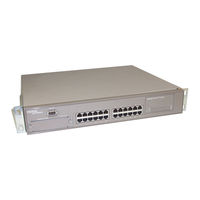
Nortel BayStack 450-12T Using Manual (400 pages)
BayStack 450 10/100/1000 Series Switch
Brand:
Nortel
| Category:
Switch
| Size: 5.95 MB
Table of Contents
Statement of Conditions
2
Table of Contents
7
Preface
25
Audience
25
Organization
26
Text Conventions
27
Acronyms
28
Related Publications
30
How to Get Help
31
Chapter 1 Baystack 450 10/100/1000 Series Switches
33
Physical Description
34
Front Panel
34
Comm Port
36
Uplink/Expansion Module Slot
36
10BASE-T/100BASE-TX Ports
36
100BASE-FX MT-RJ Ports
37
LED Display Panel
38
Table 1-1. Baystack 450 Switch LED Descriptions
40
Back Panel
42
AC Power Receptacle
42
Figure 1-5. Baystack 450 Switch Back Panel
42
Redundant Power Supply Unit (RPSU) Connector
44
Cascade Module Slot
44
Cooling Fans
45
Features
45
SNMP Support
48
Mibs
48
SNMP Traps
49
Security
49
Table 1-3. Supported SNMP Traps
49
MAC Address-Based Security
52
EAPOL-Based Security
53
Security Example
53
Overview and Terms
55
Dynamic VLAN Assignment
56
Setting up the Authentication Server
57
Authentication Process
58
System Requirements
59
Configuration Rules
60
RADIUS-Based Security
60
SNMP-Based Security
61
Flash Memory Storage
61
Switch Software Image
61
Configuration Parameters
62
Configuration and Switch Management
62
Bootp Automatic IP Configuration/Mac Address
63
Autosensing and Autonegotiation
63
Network Configurations
64
Desktop Switch Application
65
Figure 1-11. Baystack 450 Switch Used as a Desktop Switch
65
Segment Switch Application
66
Figure 1-12. Baystack 450 Switch Used as a Segment Switch
66
High-Density Switched Workgroup Application
67
Figure 1-13. Configuring Power Workgroups and a Shared Media Hub
67
ATM Application
68
Setting up an ATM Configuration
69
Fail-Safe Stack Application
70
Figure 1-15. Fail-Safe Stack Example
70
Stack Operation
71
Figure 1-16. Compatible Software Versions
71
Baystack 400-ST1 Cascade Module
73
Cascade a out Connector
73
Unit Select Switch
73
Figure 1-17. Baystack 400-ST1 Front-Panel Components
73
Cascade a in Connector
74
Base Unit
75
Stack Configurations
77
Stack up Configurations
78
Stack down Configurations
78
Figure 1-19. Stack up Configuration Example
78
Figure 1-20. Stack down Configuration Example
79
Redundant Cascade Stacking Feature
80
Virtual Local Area Networks (Vlans)
81
Supported VLAN Types
82
IEEE 802.1Q VLAN Workgroups
82
Figure 1-22. Port-Based VLAN Example
83
IEEE 802.1Q Tagging
84
Figure 1-25. 802.1Q Tagging (after Port-Based Vlan Assignment)
87
Figure 1-26. Protocol-Based Vlan Assignment
87
Figure 1-27. 802.1Q Tagging (after Protocol-Based Vlan Assignment)
88
Figure 1-28. 802.1Q Tag Assignment
89
Figure 1-29. 802.1Q Tagging (after 802.1Q Tag Assignment)
89
Vlans Spanning Multiple Switches
90
Vlans Spanning Multiple 802.1Q Tagged Switches
90
Figure 1-30. Vlans Spanning Multiple 802.1Q Tagged Switches
90
Vlans Spanning Multiple Untagged Switches
91
Shared Servers
93
Figure 1-33. Multiple Vlans Sharing Resources
93
Figure 1-35. Default Vlan Configuration Screen Example
95
Figure 1-36. Vlan Configuration Screen Example
96
Figure 1-37. Default VLAN Port Configuration Screen Example
97
Figure 1-38. VLAN Port Configuration Screen Example
98
VLAN Workgroup Summary
99
Figure 1-39. VLAN Configuration Spanning Multiple Switches
99
VLAN Configuration Rules
100
IGMP Snooping
101
IGMP Snooping Configuration Rules
105
IEEE 802.1P Prioritizing
106
Figure 1-43. Prioritizing Packets
106
Figure 1-45. Default Traffic Class Configuration Screen Example
108
Figure 1-46. Setting Port Priority Example
109
Multilink Trunks
110
Client/Server Configuration Using Multilink Trunks
111
Figure 1-48. Switch-To-Server Trunk Configuration Example
111
Figure 1-49. Client/Server Configuration Example
112
Trunk Configuration Screen Examples
113
Trunk Configuration Screen for Switch S1
113
Figure 1-51. Multilink Trunk Configuration Screen for Switch S
114
Trunk Configuration Screen for Switch S2
116
Figure 1-52. Multilink Trunk Configuration Screen for Switch S
116
Trunk Configuration Screen for Switch S3
118
Figure 1-53. Multilink Trunk Configuration Screen for Switch S3
118
Trunk Configuration Screen for Switch S4
120
Figure 1-54. Multilink Trunk Configuration Screen for Switch S4
120
Before Configuring Trunks
122
Multilink Trunking Configuration Rules
122
How the Multilink Trunk Reacts to Losing Distributed Trunk Members
124
Figure 1-55. Loss of Distributed Trunk Members
124
Spanning Tree Considerations for Multilink Trunks
125
Figure 1-56. Path Cost Arbitration Example
125
Figure 1-57. Example 1: Correctly Configured Trunk
126
Figure 1-58. Example 2: Detecting a Misconfigured Port
127
Additional Tips about the Multilink Trunking Feature
128
Port Mirroring (Conversation Steering)
129
Port-Based Mirroring Configuration
130
Address-Based Mirroring Configuration
132
Figure 1-60. Port Mirroring Port-Based Screen Example
132
Figure 1-62. Port Mirroring Address-Based Screen Example
134
Port Mirroring Configuration Rules
135
Chapter 2 Installing the Baystack 450 Switch
137
Installation Requirements
137
Figure 2-1. Package Contents
138
Installation Procedure
139
Installing the Baystack 450 Switch on a Flat Surface
139
Installing the Baystack 450 Switch in a Rack
140
Figure 2-2. Positioning the Chassis in the Rack
141
Attaching Devices to the Baystack 450 Switch
143
Connecting the 10BASE-T/100BASE-TX Ports
144
Figure 2-5. 10/100 Mb/S Port Connections
144
Connecting Fiber Optic Ports
145
Console/Comm Port
146
Connecting a Terminal to the Console/Comm Port
147
Figure 2-7. Connecting to the Console/Comm Port
147
Connecting Power
148
Verifying the Installation
150
Verifying the Installation Using the Leds
150
Figure 2-10. Observing Leds to Verify Proper Operation
150
Table 2-1. Power-Up Sequence
150
Verifying the Installation Using the Self-Test Screen
151
Figure 2-11. Baystack 450 Switch Self-Test Screen
151
Figure 2-12. Nortel Networks Logo Screen
152
Initial Setup
153
Standalone Switch Setup
153
Figure 2-13. Main Menu for Standalone Switch
154
Figure 2-14. IP Configuration/Setup Screen (Standalone Switch)
155
Stack Setup
156
Figure 2-15. Main Menu (Standalone Switch Example)
157
Figure 2-16. Main Menu (Stack Configuration Example)
157
Figure 2-17. IP Configuration/Setup Screen (Stack Configuration)
158
Chapter 3 Using the Console Interface
161
Accessing the CI Menus and Screens
162
Using the CI Menus and Screens
162
Navigating the CI Menus and Screens
163
Map of CI Menus and Screens
164
Figure 3-1. Map of Console Interface Screens
164
Main Menu
165
Figure 3-2. Console Interface Main Menu
165
Table 3-1. Console Interface Main Menu Options
166
IP Configuration/Setup
169
Figure 3-3. IP Configuration/Setup Screen
169
Table 3-2. IP Configuration/Setup Screen Fields
170
Bootp Request Mode
171
Bootp Disabled
172
Bootp or Last Address
172
Bootp When Needed
173
Bootp Always
173
SNMP Configuration
174
Figure 3-4. SNMP Configuration Screen
174
Table 3-3. SNMP Configuration Screen Fields
174
System Characteristics
176
Figure 3-5. System Characteristics Screen
176
Table 3-4. System Characteristics Screen Fields
177
Switch Configuration
179
MAC Address Table
179
Figure 3-6. Switch Configuration Menu
179
Table 3-5. Switch Configuration Menu Options
180
Figure 3-7. MAC Address Table Screen
182
MAC Address Table
182
Table 3-6. MAC Address Table Screen Fields
183
MAC Address-Based Security
184
Figure 3-8. MAC Address Security Configuration Menu
185
MAC Address Security Configuration
186
Table 3-7. MAC Address Security Configuration Menu Options
186
Figure 3-9. MAC Address Security Configuration Screen
187
Table 3-8. MAC Address Security Configuration Screen Fields
188
Figure 3-10. MAC Address Security Port Configuration (Screen 1 of 2)
190
MAC Address Security Port Configuration
190
Figure 3-11. MAC Address Security Port Configuration (Screen 2 of 2)
191
Table 3-9. MAC Address Security Port Configuration Screen Fields
192
Figure 3-12. MAC Address Security Port Lists Screens (5 Screens)
193
MAC Address Security Port Lists
193
Figure 3-13. MAC Address Security Port Lists Screen
194
Table 3-10. MAC Address Security Port Lists Screen Fields
194
Figure 3-14. MAC Address Security Table Screens (16 Screens)
197
MAC Address Security Table
197
Figure 3-15. MAC Address Security Table Screen
198
Table 3-11. MAC Address Security Table Screen Fields
199
EAPOL Security Configuration
200
Figure 3-16. EAPOL Security Configuration Screen
201
Table 3-12. EAPOL Security Configuration Screen Options
201
VLAN Configuration Menu
204
Figure 3-17. VLAN Configuration Menu
205
Table 3-13. VLAN Configuration Menu Options
205
VLAN Configuration
206
Figure 3-18. VLAN Configuration Screen
207
Table 3-14. VLAN Configuration Screen Fields
209
Table 3-15. Predefined Protocol Identifier (PID)
210
VLAN Port Configuration
212
Figure 3-19. VLAN Port Configuration Screen
213
Table 3-17. VLAN Port Configuration Screen Fields
215
Figure 3-20. VLAN Display by Port Screen
216
VLAN Display by Port
216
Table 3-18. VLAN Display by Port Screen Fields
217
Traffic Class Configuration
217
Figure 3-21. Traffic Class Configuration Screen
218
Table 3-19. Traffic Class Configuration Screen Fields
218
Figure 3-22. Port Configuration Screen (1 of 2)
219
Port Configuration
219
Figure 3-23. Port Configuration Screen (2 of 2)
220
Table 3-20. Port Configuration Screen Fields
221
Figure 3-24. High Speed Flow Control Configuration Screen
222
High Speed Flow Control Configuration
222
Choosing a High Speed Flow Control Mode
223
Table 3-21. High Speed Flow Control Configuration Screen Fields
223
Asymmetric Mode
224
Symmetric Mode
224
Multilink Trunk Configuration
224
Figure 3-25. Multilink Trunk Configuration Menu
225
Table 3-22. Multilink Trunk Configuration Menu Options
225
Multilink Trunk Configuration Screen
226
Figure 3-26. Multilink Trunk Configuration Screen
227
Table 3-23. Multilink Trunk Configuration Screen Fields
227
Multilink Trunk Utilization Screen
228
Figure 3-27. Multilink Trunk Utilization Screen (1 of 2)
229
Figure 3-28. Multilink Trunk Utilization Screen (2 of 2)
230
Table 3-24. Multilink Trunk Utilization Screen Fields
230
Port Mirroring Configuration
231
Figure 3-29. Port Mirroring Configuration Screen
232
Table 3-25. Port Mirroring Configuration Screen Fields
233
Table 3-26. Monitoring Modes
234
Figure 3-30. Rate Limiting Configuration Screen (1 of 2)
235
Rate Limiting Configuration
235
Figure 3-31. Rate Limiting Configuration Screen (2 of 2)
236
Table 3-27. Rate Limiting Configuration Screen Fields
237
Figure 3-32. IGMP Configuration Menu
238
IGMP Configuration
239
Table 3-28. IGMP Configuration Menu Options
239
Figure 3-33. IGMP Configuration Screen
240
Table 3-29. IGMP Configuration Screen Fields
242
Multicast Group Membership
243
Figure 3-34. Multicast Group Membership Screen
244
Table 3-30. Multicast Group Membership Screen Options
244
IGMP Configuration Menu
238
Figure 3-35. Port Statistics Screen
245
Port Statistics
245
Table 3-31. Port Statistics Screen Fields
246
ATM Configuration Menu
249
Figure 3-36. ATM Configuration Menu
249
Before Configuring Your ATM MDA
250
LEC Configuration
251
Table 3-32. ATM Configuration Menu Options
251
Figure 3-37. LEC Configuration Screen
252
Table 3-33. LEC Configuration Screen Fields
252
ATM MDA Configuration
254
Figure 3-38. ATM MDA Configuration Screen
255
ATM MDA Software Download
257
Table 3-34. ATM MDA Configuration Screen Fields
257
Figure 3-39. ATM MDA Software Download Screen
258
Table 3-35. ATM MDA Software Download Screen Fields
258
Console/Comm Port Configuration
260
Figure 3-40. Console/Comm Port Configuration Screen
260
Table 3-36. Console/Comm Port Configuration Screen Fields
260
Identify Unit Numbers
267
Renumber Stack Units
267
Figure 3-41. Renumber Stack Units Screen
268
Table 3-37. Renumber Stack Units Screen Options
268
Display Hardware Units
269
Spanning Tree Configuration
270
Figure 3-42. Hardware Unit Information Screen
270
Figure 3-43. Spanning Tree Configuration Menu
271
Spanning Tree Port Configuration
271
Table 3-38. Spanning Tree Configuration Menu Options
271
Figure 3-44. Spanning Tree Port Configuration Screen (1 of 2)
272
Figure 3-45. Spanning Tree Port Configuration Screen (2 of 2)
273
Table 3-39. Spanning Tree Port Configuration Screen Fields
273
Display Spanning Tree Switch Settings
275
Figure 3-46. Spanning Tree Switch Settings Screen
275
Table 3-40. Spanning Tree Switch Settings Parameters
276
TELNET/SNMP Manager List Configuration
278
Figure 3-47. TELNET/SNMP Manager List Configuration Screen
278
Table 3-41. TELNET/SNMP Manager List Configuration Screen Fields
279
Software Download
281
Figure 3-48. Software Download Screen
282
Table 3-42. Software Download Screen Fields
282
Table 3-43. LED Indications During the Software Download Process
284
Configuration File
285
Figure 3-49. Configuration File Download/Upload Screen
285
Table 3-44. Configuration File Download/Upload Screen Fields
286
Table 3-45. Parameters Not Saved to the Configuration File
287
Display Event Log
288
Figure 3-50. Event Log Screen
288
Excessive Bad Entries
289
Figure 3-52. Sample Event Log Entry Exceeding the Write Threshold
290
Figure 3-53. Sample Event Log Entry Showing Flash Update Status
290
Flash Update
290
Write Threshold
290
Save Current Settings
291
Reset
291
Figure 3-54. Self-Test Screen after Resetting the Switch
291
Figure 3-55. Nortel Networks Logo Screen
292
Reset to Default Settings
293
Figure 3-56. Self-Test Screen after Resetting to Default Settings
294
Figure 3-57. Nortel Networks Logo Screen after Resetting to Default Settings
295
Logout
296
Chapter 4 Troubleshooting
297
Interpreting the Leds
297
Table 4-1. Baystack 450 Switch LED Descriptions
300
Diagnosing and Correcting the Problem
301
Normal Power-Up Sequence
302
Table 4-2. Corrective Actions
303
Port Connection Problems
304
Autonegotiation Modes
304
Port Interface
305
Software Download Error Codes
305
Table 4-3. Software Download Error Codes
306
Appendix A Technical Specifications
307
Environmental
307
Electrical
308
Physical Dimensions
308
Performance Specifications
308
Network Protocol and Standards Compatibility
309
Data Rate
309
Interface Options
309
Safety Agency Certification
310
Electromagnetic Emissions
310
Electromagnetic Immunity
310
Declaration of Conformity
310
Appendix B Gigabit Fiber Optical Characteristics
311
1000BASE-SX Models
311
Operating Range
311
Transmit Characteristics
312
Receive Characteristics
313
Worst-Case Power Budget and Penalties
313
Table B-3. 1000BASE-SX Receive Characteristics
313
1000BASE-LX Models
314
Operating Range
314
Table B-5. Operating Range for 1000BASE-LX
314
Table B-4. Worst-Case 1000BASE-SX Power Budget and Penalties
314
Transmit Characteristics
315
Receive Characteristics
315
Worst-Case Power Budget and Penalties
316
Table B-7. 1000BASE-LX Receive Characteristics
316
Table B-8. Worst-Case 1000BASE-LX Power Budget and Penalties
316
Appendix C Media Dependent Adapters
317
10Base-T/100Base-Tx Mda
318
Figure C-1. 400-4TX MDA Front Panel
318
Table C-1. 400-4TX MDA Components
318
100BASE-FX Mdas
319
Table C-2. 100BASE-FX MDA Components
321
1000BASE-SX Mdas
322
Table C-3. 1000BASE-SX MDA Components
324
1000BASE-LX Mdas
325
Table C-4. 1000BASE-LX MDA Components
327
Asynchronous Transfer Mode (ATM) Mdas
328
Table C-5. 450-2M3 and 450-2S3 MDA Description
330
Gigabit Interface Converter (GBIC) MDA
331
Installing an MDA
333
Table C-6. 450-1GBIC MDA Components
333
Figure C-7. Installing an MDA
334
Installing Gbics
335
Replacing an MDA
335
Table C-7. Available GBIC Models
335
Figure C-8. GBIC Case Styles
336
Installation
336
Figure C-10. Removing a GBIC
337
Removing an Installed GBIC
337
1000BASE-LX Multimode Applications
338
Appendix Datm Overview
339
ATM Terminology
339
LAN Emulation (LANE
339
Figure D-1. ATM LAN Emulation Model
340
Emulated LAN (ELAN
341
LAN Emulation Client (LEC
341
LAN Emulation Configuration Server (LECS
342
LAN Emulation Server (LES
342
Broadcast and Unknown Server (BUS
342
User-To-Network Interface (UNI
343
ATM Data Transmission
343
Configuration Concepts
344
Figure D-2. ATM Transmission Components
344
Available Services
345
Lane
346
UNI Support
346
LECS Address Methods
346
Phy
346
ELAN VLAN Mapping
345
Virtual Ports
347
LEC Failover
348
Figure D-5. LEC Vports with Spanning Tree Enabled (1
349
Spanning Tree on LEC Vports
349
Figure D-6. LEC Vports with Spanning Tree Disabled (2 of 2)
350
Configuration Rules
351
Mixed Stack Configurations
351
Initial Configuration
351
Enabling a LEC
351
Lecs and VLAN Membership
352
Console Differences
352
Appendix E Quick Steps to Features
355
Configuring 802.1Q Vlans
355
Configuring 802.1Q Vlans
356
Figure E-2. Configuring 802.1Q Vlans (2
357
Figure E-3. Configuring 802.1Q Vlans (3 of 3)
358
Configuring Security Settings
359
Figure E-4. Security Configurations
359
Figure E-5. MAC Address-Based Security (1
360
Figure E-6. MAC Address-Based Security (2 of 2)
361
Figure E-7. EAPOL-Based Security
362
Figure E-8. RADIUS-Based Security (1 of 5)
363
Figure E-9. RADIUS-Based Security (2 of 5)
364
Figure E-10. RADIUS-Based Security (3
365
Figure E-11. RADIUS-Based Security (4 of 5)
366
Figure E-12. RADIUS-Based Security (5 of 5)
367
Figure E-13. SNMP-Based Security
368
Configuring the Baystack 450-2M3/2S3 Mdas
369
Figure E-14. Configuring the Baystack 450-2M3/2S3 MDA (1
369
Configuring Multilink Trunks
372
Configuring Port Mirroring
373
Configuring IGMP Snooping
375
Appendix F Connectors and Pin Assignments
379
RJ-45 (10BASE-T/100BASE-TX) Port Connectors
379
MDI and MDI-X Devices
380
MDI-X to MDI Cable Connections
381
MDI-X to MDI-X Cable Connections
382
DB-9 (RS-232-D) Console/Comm Port Connector
383
Appendix G Default Settings
385
Table G-1. Factory Default Settings for the Baystack 450 Switch
385
Advertisement
Nortel BayStack 450-12T Specifications (8 pages)
Stackable Up to 8 Units and 224 Ports
Brand:
Nortel
| Category:
Switch
| Size: 1.52 MB
Advertisement
Related Products
Nortel 4500 Series
Nortel 4500 FIPS
Nortel BayStack 450-12F
Nortel BayStack 450-24T
Nortel Nortel Contivity Extranet Switch 4500
Nortel 450 series
Nortel BayStack 450 10 Series
Nortel BayStack 450 100 Series
Nortel BayStack 450 1000 Series
Nortel 4526FX
Nortel Categories
IP Phone
Telephone
Switch
Software
Server
More Nortel Manuals
Login
Sign In
OR
Sign in with Facebook
Sign in with Google
Upload manual
Upload from disk
Upload from URL