
Related Manuals for Teledyne CP Series


Summary of Contents for Teledyne CP Series
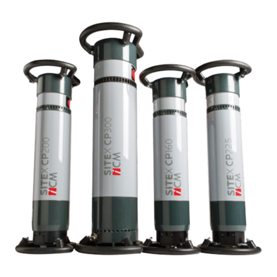
- Page 1 User Manual CP Series Version 3.1 – June 2020 Zoning « Les Plenesses » | Rue du Progrès 3 | 4821 Andrimont – Belgium | Tel.: +32 (0)87 440 150 | Fax : +32 (0)87 440 160 | icm.sales@teledyne.com...
-
Page 2: Table Of Contents
CP Series Version 3.1 – June 2020 REVISION HISTORY ____________________________________________________________ 6 WARNINGS _____________________________________________________________ 7 Safety warnings ______________________________________________________________ 7 INTRODUCTION _________________________________________________________ 8 The CP SERIES, PowerBox and PowerModule ______________________________________ 8 2.1.1 Operating Range ___________________________________________________________________ 8 2.1.2 Technical specifications ____________________________________________________________ 11 2.1.3... - Page 3 User Manual CP Series Version 3.1 – June 2020 4.2.1 Connections _____________________________________________________________________ 32 4.2.2 Power On________________________________________________________________________ 33 4.2.3 Preheating / Warm-up _____________________________________________________________ 34 4.2.4 Setting kV, mA and exposure time ____________________________________________________ 35 4.2.5 Using the Constant Power function (Pct) _______________________________________________ 35 4.2.6...
- Page 4 User Manual CP Series Version 3.1 – June 2020 Errors _____________________________________________________________________ 48 5.7.1 Current errors ____________________________________________________________________ 48 5.7.2 Error status ______________________________________________________________________ 48 5.7.3 View history _____________________________________________________________________ 49 5.7.4 Export to USB ____________________________________________________________________ 49 Demo mode ________________________________________________________________ 49 ICM functions _______________________________________________________________ 49...
- Page 5 User Manual CP Series Version 3.1 – June 2020 Audible/flashing lights ________________________________________________________ 55 Magnetic foot for warning lights ________________________________________________ 56 Tripod for flashing light _______________________________________________________ 56 Peli Storm ™ transport case____________________________________________________ 57 Tripod for generator _________________________________________________________ 57 Aluminum transport case with CP tripod _________________________________________ 58...
-
Page 6: Revision History
Also, additional features may become available which are not described at all in this version of the User Manual. TELEDYNE ICM will update this User Manual to incorporate these changes at its own discretion and without prior notification. It is therefore recommended to contact TELEDYNE ICM or your local distributor to obtain the latest version of the User manual if you see behavioral changes or new functionalities after a repair or upgrade. -
Page 7: Warnings
User Manual CP Series Version 3.1 – June 2020 1. WARNINGS AFETY WARNINGS The Goods can cause death, personal injury or property damage if they are used, operated, maintained, stored or disposed of improperly. In particular, the Goods may emit x-ray radiation, so adequate safety precautions must be taken to minimize exposure. -
Page 8: Introduction
With the new CP SERIES also comes a new control unit, the PowerBox, which will provide a 380 DC voltage supply from which the CP SERIES’s Power module will generate the required power signals to achieve the high voltage as well as a highly configurable interface to interact with the user and 3rd party devices. - Page 9 User Manual CP Series Version 3.1 – June 2020 CP160D OPERATING RANGE Maximum power curve: kV x mA = 900 Watts 90 100 110 120 130 140 150 160 170 180 CP200D OPERATING RANGE Maximum power curve: kV x mA = 900 Watts...
- Page 10 User Manual CP Series Version 3.1 – June 2020 CP225D OPERATING RANGE Maximum power curve: kV x mA = 900 Watts 0 10 20 30 40 50 60 70 80 90 100110120130140150160170180190200210220230240250 CP300C OPERATING RANGE 11.0 10.0 CP300C...
-
Page 11: Technical Specifications
User Manual CP Series Version 3.1 – June 2020 CP200DS OPERATING RANGE 11.0 10.0 CP200DS 2.1.2 T ECHNICAL SPECIFICATIONS CP200DS Technical specifications Units CP160D CP200D CP225D CP300D CP300C Output kilovolt range 10 to 200 30 to 300 10 to 200... - Page 12 User Manual CP Series Version 3.1 – June 2020 Maximum useful angle (°) 60 x 40 60 x 40 60 x 40 60 x 40 N.A. 60 x 40 X-ray directional elliptical elliptical elliptical elliptical elliptical beam Maximum useful angle (°)
-
Page 13: Exposure Charts
User Manual CP Series Version 3.1 – June 2020 2.1.3 E XPOSURE HARTS... -
Page 14: Component Description
User Manual CP Series Version 3.1 – June 2020 3. COMPONENT DESCRIPTION CP SERIES X- RAY GENERATOR 3.1.1 M ECHANICAL DIMENSIONS CP160D/CP200D/CP225D CP300D... - Page 15 User Manual CP Series Version 3.1 – June 2020 CP300C...
- Page 16 User Manual CP Series Version 3.1 – June 2020 CP200DS...
-
Page 17: Guard Rings
User Manual CP Series Version 3.1 – June 2020 3.1.2 G UARD RINGS The guard rings provide handles to easily manipulate and position the generator but more importantly they provide shock absorption in case the generator is dropped. 3.1.3 C... -
Page 18: Maintenance Of The Carousel
User Manual CP Series Version 3.1 – June 2020 Custom diaphragm By standard, a 480x100@700mm film shape is provided. This will reduce the shape of the X-ray beam to match the used film and consequently reduce the leakage radiation. Custom shapes with different sizes can be ordered from ICM to match your application. -
Page 19: Interconnection Socket
3.1.5 I NTERCONNECTION SOCKET The interconnection cable connects the PowerBox with the CP SERIES generator. The socket of the interconnection cable on the generator side can easily be switched between an axial or radial connection position. Below is the procedure explaining how to switch from one position to another:... - Page 20 User Manual CP Series Version 3.1 – June 2020 Rotate the connector 180° And screw back the 4 screws.
- Page 21 User Manual CP Series Version 3.1 – June 2020 CP300D/300C Remove the 3 screws fixing the cover Lift gently the cover and disconnect the fan connector...
- Page 22 User Manual CP Series Version 3.1 – June 2020 Remove completely the cover and unscrew the cap Unscrew the connector, and switch its position with the cap Make sure to replace the cap at the previous location of the connector and fix everything with the screws.
-
Page 23: Cooling Fan
3.1.6 C OOLING FAN The main cooling fan is a very high-power fan providing the required cooling to the CP SERIES generator’s anode. Due to the high speed and high air displacement volume when the fan is working at maximum speed, a siren-like sound will be generated. -
Page 24: Powermodule
The PowerModule converts a 380Vdc power supplied by the PowerBox into a signal that will generate the requested kV and mA in the CP SERIES generator. This PowerModule is a standard component and is identical for all Site-X CP generators. It can easily be replaced, and no further configuration or calibration is required, even on site. -
Page 25: Front Panel
User Manual CP Series Version 3.1 – June 2020 3.3.2 F RONT PANEL 1: Main display 9: STOP button with built-in red light 2: Secondary display 10: START button with built-in green light 3: Time key 11: Main power switch... -
Page 26: Power Connector
The recommended minimum power rating of the power generator is 2kVA. It is possible to power the CP SERIES generator set from a car or truck battery when an appropriate 12/24Vdc to 230Vac adaptor is used. The current consumption on 24V will be approximately 60A. - Page 27 User Manual CP Series Version 3.1 – June 2020 The maximum total power consumption for the 24V powered lamps is 15W. The maximum total switched current of the relays is 2A. A. W IRE CUT The wire cut (pin M) needs to be connected to ground (pin A) to enable the PowerBox to detect if a cable is connected to the interlock connection.
-
Page 28: Handle
3.3.7 USB PORTS ASTER PORT The master USB port can be used to upgrade the CP SERIES generator or PowerBox software, to import new languages and download the shots and errors records stored in the PowerBox for archiving or analyses. - Page 29 User Manual CP Series Version 3.1 – June 2020 RS 422 PORT This port has the same function that the USB slave port but using RS422 protocol. The RS 422 connection is made through an HIROSE HR10-7R-6S(73) connector on the Power Box. You may want to use HIROSE HR10-7P-6P connector on the connection cable side.
-
Page 30: Operation
The CP SERIES X-ray generator produces ultra-high voltage internally. For the electrical safety shut-off devices to operate optimally in the event of failure or an accident, it is essential that the CP SERIES generator or PowerBox are effectively connected to an earth of low impedance (< 10 Ohm). -
Page 31: Various General Precautions To Be Observed
1. Only authorized personnel shall use the CP SERIES generator set. 2. Take care that the CP SERIES generator is never used with a supply voltage exceeding 264VAC. 3. Make sure that you ALWAYS work with the equipment well earthen. Check this if in doubt. -
Page 32: Daily Use
4.2.1 C ONNECTIONS When connecting the cables to the PowerBox and CP SERIES generator, make sure to close the connector until a ‘click’ can be felt. This will ensure a good connection and will prevent the cables from getting disconnected while the equipment is in use. -
Page 33: Power On
3. Preheat required for kVmax. When the CP SERIES generator has not been used for more than 8 hours, a preheating is required to operate at maximum kV. The message further asks the operator if he would the maximum kV to be programmed for the preheating. -
Page 34: Preheating / Warm-Up
PowerBox based on the kV settings during the last exposure, the idle time of the CP SERIES generator since that last exposure and the set kV. The data which is required for the calculation of the preheating time is taken from the CP SERIES’s internal memory. -
Page 35: Setting Kv, Ma And Exposure Time
User Manual CP Series Version 3.1 – June 2020 the first step, after what a rest time is enforced. When the rest time is elapsed, the operator must press the “Start” button to achieve the second step and so on until all the steps have been achieved. -
Page 36: Emergency Stop
User Manual CP Series Version 3.1 – June 2020 4.2.6 E MERGENCY The emitting of X-rays during preheating or while making an exposure, can always be stopped immediately by pressing the STOP button (9) or by turning OFF the Safety key (12). -
Page 37: Powerbox Menu
PowerBox menu, these items are preceded by a padlock symbol. There are 2 reasons an item can be locked: 1. The item refers to the CP SERIES generator and this one is not connected to the PowerBox. Connect the generator to have access to this item. -
Page 38: Exposure Calculation (Optional)
User Manual CP Series Version 3.1 – June 2020 XPOSURE CALCULATION OPTIONAL Note: This is an optional feature and will only be available when purchased. 5.2.1 C ALCULATE The exposure calculator software allows for automatic calculation of the Exposure calc required kV or the required exposure time (T). -
Page 39: Icm Chart
User Manual CP Series Version 3.1 – June 2020 5.2.2 ICM CHART Newly delivered equipment comes pre-loaded with standard ICM charts for the most used film types and materials. Custom charts for different film brand, film type or specific material can also be entered in the PowerBox and used for exposure time or kV calculations. -
Page 40: Memory Access
The result is a table of 2 thicknesses per kV line. The number and range of kV lines that will be recorded is free to choose within the operating range of the CP SERIES generator. The table that was found by doing the density measurements on the films can now be recorded in the PowerBox. -
Page 41: Settings
CP Series Version 3.1 – June 2020 • Gen Model: Generator Model (Currently only CP SERIES is available) Select the ‘Confirm’ item and press OK to store the set of entries. ETTINGS The settings menu gives access to various settings of parameters and Settings equipment behavior. -
Page 42: Door Control
AMP CONTROL All lamp on the PowerBox front panel, the externally connectable lamp, Lamps control siren or buzzer outputs and the warning lamp on the CP SERIES All off generator are equipped with a ‘device failure’ detection. When enabled the PowerBox will detect a failure of one or more of these devices and Lamp 1 display an error indicating which lamp or buzzer is defect. -
Page 43: Bluetooth
5.4.6 D ATE AND TIME There is a real time clock in both the PowerBox and the CP SERIES Date and Time generator indicating the UTC time and date. The CP SERIES generator’s... -
Page 44: Language
UTC. ‘Confirm’ will set the real time clock in the CP SERIES generator to the UTC time of the PowerBox. This function is however reserved only for authorized After Sales service centers as changing the date in the CP SERIES generator will have an influence on the preheating time and may lead to equipment failure if used incorrectly. -
Page 45: Screen
Standby time Set the time in seconds after which the display will revert to the standby. i.e.: Sleep brightness. Value can be adjusted between 1 & 255 seconds. 5.4.10 AROUSEL There are 5 positions of the carousel as illustrated in the CP SERIES Carousel generator’s component description chapter. Control When the ‘Control’... -
Page 46: Limitations
5.4.12 EN LAMP Sets the behavior of the generator’s lamp during the shot. 5.4.13 AN MODE The speed of the cooling main fan of the CP SERIES generator can be Settings set to operate in 3 modes: Fan Mode silent 1. -
Page 47: Units
User Manual CP Series Version 3.1 – June 2020 between 5 and 255 seconds. Any value below or above these limits will automatically be adjusted to the nearest limit. 5.4.15 NITS Set your preferred unit system, metric or imperial, by pressing the ‘OK’... -
Page 48: Powerbox
URRENT ERRORS Export to USB ‘Current errors’ will provide a full text explanation of the current error if the PowerBox or CP SERIES generator is facing a warning or error situation. Suggestions on how to resolve the problem are displayed on the main display (1). -
Page 49: View History
Data access Errors Note: To be able to enter the ‘Demo mode’ the CP SERIES generator Demo mode must be disconnected. The Safety Key Switch (12) needs to be in the XO position! -
Page 50: Troubleshooting
6.2.1 E56: G AS LEAK The CP SERIES constantly makes sure the pressure is high enough according to SF6 temperature. If it is too low a warning message will be displayed indicating that the gas pressure is getting low. Please schedule maintenance for the CP SERIES generator to identify any gas leaks and refill the generator with SF6. -
Page 51: E164: Car. Preheat
Once the gas pressure is high enough to start an exposure, the CP SERIES will keep itself warm enough as long as you use it regularly. -
Page 52: E71: Pb T° Rad Max
User Manual CP Series Version 3.1 – June 2020 6.3.7 E71: PB T° RAD MAX The temperature of the radiator of the PowerBox has become too high. Make sure there is enough room for air circulation, move the PowerBox to a cooler or shaded area and allow it to cool down in stand-by mode before attempting to make further exposures. -
Page 53: E149: Car. Pointer
User Manual CP Series Version 3.1 – June 2020 6.3.16 E149: C POINTER The carousel is in the laser pointer position. Making an exposure with the carousel in the laser pointer position may damage the electronics of the laser pointer. The laser pointer would also show up in the developed film. -
Page 54: Accessories
User Manual CP Series Version 3.1 – June 2020 7. ACCESSORIES INGLE FLASHING LIGHT ICM order number 00003071. A single red warning light in a reinforced housing with a 20 m connection cable attached. The functioning of the light – always on or flashing during X-ray active – can be controlled by the PowerBox. -
Page 55: Audible/Flashing Lights
User Manual CP Series Version 3.1 – June 2020 Disconnect the 2 wires from the connecting element, and then remove the 2 screws holding it White wire is connected to terminal 0 and red one is connected to terminal 1. -
Page 56: Magnetic Foot For Warning Lights
User Manual CP Series Version 3.1 – June 2020 AGNETIC FOOT FOR WARNING LIGHTS ICM order number 00003406. The warning lights and siren described in point 8.1 and 8.2 can be equipped with a magnetic foot, allowing them to be attached to metal objects such as pipelines, metal tank walls or support structures. -
Page 57: Peli Storm Transport Case
RIPOD FOR GENERATOR ICM order number 00003073. The tripod for the CP SERIES generator allows adjustment of height and rotation in 3 axes of the generator itself. This allows the CP SERIES generator to be positioned in any position or orientation desired. -
Page 58: Aluminum Transport Case With Cp Tripod
TRIPOD ICM order number 00003434. An aluminum transport case which can hold the CP SERIES generator, the PowerBox, the 10m power cable, a 20m interconnection cable, a 3-color flashing light with built-in siren and its tripod and the CP SERIES generator tripod. -
Page 59: Exposure Time Calculator
User Manual CP Series Version 3.1 – June 2020 XPOSURE TIME CALCULATOR ICM order number 00003074. Unlock code for the exposure time calculator software. 7.10 I NTERCONNECTION CABLE EXTENSION UP TO ICM order number 00003438. Standard extension cables for the interconnection cable are available in lengths of 20 meter. - Page 60 User Manual CP Series Version 3.1 – June 2020 as described in 3.3.5. Thus, it is necessary to adjust the interlocks in order to switch on “Lamp2” and “Lamp3” during exposure. This can be done by selecting the “Dual Flashlight” standard, as described in 5.4.4, or in manual mode.
-
Page 61: Pre-Sets Configuration
User Manual CP Series Version 3.1 – June 2020 8. PRE-SETS CONFIGURATION Lamp 1 = green Lamp 2 = yellow Lamp 3 = red... -
Page 62: Communication Protocol
User Manual CP Series Version 3.1 – June 2020 9. COMMUNICATION PROTOCOL RAMES AND SETTINGS This chapter describes the communication protocol between the PowerBox and external world (typically a PC). Two types of connections are available: UART (RS422) or USB. - Page 63 User Manual CP Series Version 3.1 – June 2020 iSerialNumber "12345678" bNumConfigurations Configuration Descriptor 1 Bus Powered, 100 mA Offset Field Size Value Description bLength bDescriptorType Configuration wTotalLength 0022h bNumInterfaces bConfigurationValue iConfiguration bmAttributes Bus Powered 4..0: Reserved ...00000 5: Remote Wakeup ..0..
-
Page 64: Messages
User Manual CP Series Version 3.1 – June 2020 Offset Field Size Value Description bLength bDescriptorType Endpoint bEndpointAddress 1 In bmAttributes Interrupt 1..0: Transfer Type ..11 Interrupt 7..2: Reserved 000000.. wMaxPacketSize 0040h 64 bytes bInterval 10 ms Interface 0 HID Report Descriptor Vendor-Defined 1... - Page 65 User Manual CP Series Version 3.1 – June 2020 During the shot, a watchdog command (#XO) has to be sent every second to the PowerBox so it can make sure that everyone is up and running. The PowerBox will answer by !XO. If the watchdog is not sent, the shot will be stopped.
- Page 66 User Manual CP Series Version 3.1 – June 2020 Command description Fields description Command syntax Description Reply from PowerBox Field name Description units <XXX> Programmed kV setup value Ask for actual shot values !SE<XXX>,<YYY>,<ZZZ> <YYY> Programmed mA setup value mA/10 <ZZZ>...
- Page 67 User Manual CP Series Version 3.1 – June 2020 Command description Fields description Command syntax Description Reply from PowerBox Field name Description units <XXXX> Requested exposure time value <YYYY> Programmed exposure time value 0 : no error 1 : no generator connected...
- Page 68 User Manual CP Series Version 3.1 – June 2020 Command description Fields description Command syntax Description Reply from PowerBox Field name Description units Status code: 0: Connecting 1: No generator 2: Ready to start 3: Error state 4: Preheating required 5: Reserved for future use N.A.
-
Page 69: Recycling
TELEDYNE ICM confirms comply with European regulations and fulfil the obligations under Directive 2012/19 / EU on waste electrical and electronic equipment. TELEDYNE ICM supports the recycling of its products when they are end of life. The cost of collection is not included in the standard package.