
Related Manuals for Omron TJ1/GRT1


Summary of Contents for Omron TJ1/GRT1
- Page 1 Cat. No. I51E-EN-05 Trajexia motion control system TJ1-MC04, TJ1-MC16, TJ1-ML04, TJ1-ML16, TJ1-PRT, TJ1-DRT, TJ1-CORT, TJ1-FL02 GRT1-ML2 hardware reference manual...
- Page 2 Every precaution has been taken in the preparation of this manual. Nevertheless, OMRON assumes no responsibility for errors or omissions. Neither is any liability assumed for damages resulting from the use of the information contained in this publication.
- Page 3 Describes the installation and operation Omron Smartslice W455-E1 Describes the installation and operation Driver manual of Sigma-II Servo Drivers GRT1-Series, slice I/ of Omron slice I/O units O units, Operation Sigma-III with SIEP S800000 11 Describes the installation and operation manual MECHATROLINK...
- Page 4 Connect the TJ1-MC__ to Trajexia Studio software. Refer to the Programming Manual. WARNING Open the terminal window and type the following commands: Failure to read and understand the information provided in this manual may result in personal injury or death, damage to the pro- Type in the terminal window.
-
Page 5: Table Of Contents
Contents Safety warnings and precautions................................1 Intended audience ............................................1 General precautions ............................................1 Safety precautions ............................................1 Operating environment precautions........................................2 Application precautions.............................................3 Unit assembly precautions..........................................5 Conformance to EC Directives Conformance ....................................6 System philosophy ....................................... 7 Introduction ...............................................7 Motion control concepts ............................................8 Servo system principles ..........................................19 Trajexia system architecture .........................................22 Cycle time ..............................................23 Program control and multi-tasking ........................................29... -
Page 6: Safety Warnings And Precautions
WARNING on lives and property if used improperly, consult your OMRON Emergency stop circuits, interlock circuits, limit circuits, and similar representative. -
Page 7: Operating Environment Precautions
Safety warnings and precautions WARNING Caution The TJ1 will turn off the WDOG when its self-diagnosis function Tighten the screws on the terminal block of the Power Supply Unit detects any error.As a countermeasure for such errors, external to the torque specified in this manual. safety measures must be provided to ensure safety in the system. -
Page 8: Application Precautions
Safety warnings and precautions Caution Caution The operating environment of the TJ1 System can have a large Take appropriate measures to ensure that the specified power with effect on the longevity and reliability of the system. the rated voltage and frequency is supplied. Be particularly careful Improper operating environments can lead to malfunction, failure, in places where the power supply is unstable. - Page 9 Safety warnings and precautions Caution Caution Always turn off the power supply to the system before attempting Double-check all the wiring before turning on the power supply. any of the following. Incorrect wiring may result in burning. Not turning off the power supply may result in malfunction or elec- tric shock.
-
Page 10: Unit Assembly Precautions
Safety warnings and precautions Caution Caution Do not pull on the cables or bend the cables beyond their natural The TJ1 will start operating in RUN mode when the power is limit. Doing so may break the cables. turned on and if a BASIC program is set to Auto Run mode. Caution Caution Before touching the system, be sure to first touch a grounded... -
Page 11: Conformance To Ec Directives Conformance
The concepts for the directives EMC and Low Voltage are as follows: EMC Directives OMRON devices that comply with EC Directives also conform to the related EMC standards so that they can be more easily built into other devices or machines. -
Page 12: System Philosophy
System philosophy System philosophy Introduction The system philosophy is centred around the relationship between: fig. 1 • System architecture • Cycle time AXIS CONTROL LOOP TJ1-MC__ • Program control and multi-tasking AXIS TYPE AXIS TYPE AXIS TYPE Buffer & Buffer & Position Position Program Buffer... -
Page 13: Motion Control Concepts
System philosophy CPU task Operation Second CPU task High priority process Third CPU task Motion Sequence (only if SERVO_PERIOD=0.5ms) LED Update High priority process Fourth CPU task External Communications Program A program is a piece of BASIC code. Process Is a program in execution with a certain priority assigned. Process 0 to 12 are Low priority processes and Process 13 and 14 are High priority processes. - Page 14 System philosophy parameter. The origin point of the coordinate system can be determined using the DEFPOS command. This command re-defines the current position to zero or any other value. A move is defined in either absolute or relative terms. An absolute move fig.
- Page 15 System philosophy Relative and absolute moves To move a single axis either the command MOVE for a relative move or the fig. 3 command MOVEABS for an absolute move is used. Each axis has its own move characteristics, which are defined by the axis parameters. MOVEABS(100) AXIS(0) MOVEABS(50) AXIS(1) Suppose a control program is executed to move from the origin to an axis...
- Page 16 System philosophy The two speed profiles in these figures show the same movement with an fig. 5 acceleration time respectively a deceleration time of 2 seconds. Again, Axis A is the time, axis B is the speed. ACCEL=5 DECEL=10 SPEED=10 MOVE(40) fig.
- Page 17 System philosophy Acceleration distance Deceleration time Deceleration distance Constant speed distance Total time Continuous moves The FORWARD and REVERSE commands can be used to start a continuous movement with constant speed on a certain axis. The FORWARD command moves the axis in positive direction and the REVERSE command in negative direction.
- Page 18 System philosophy Linear interpolation In applications it can be required for a set of motors to perform a move fig. 7 operation from one position to another in a straight line. Linearly interpolated moves can take place among several axes. The commands MOVE and MOVEABS are also used for the linear interpolation.
- Page 19 System philosophy Circular interpolation It may be required that a tool travels from the starting point to the end point fig. 8 in an arc of a circle. In this instance the motion of two axes is related via a circular interpolated move using the MOVECIRC command.
- Page 20 System philosophy Electronic gearbox The TJ1-MC__ is able to have a gearbox link from one axis to another as if fig. 10 there is a physical gearbox connecting them. This can be done using the CONNECT command in the program. In the command the ratio and the axis to link to are specified.
- Page 21 System philosophy Linked CAM control Next to the standard CAM profiling tool the TJ1-MC__ also provides a tool to fig. 11 link the CAM profile to another axis. The command to create the link is called CAMBOX. The travelling speed through the profile is not determined by the axis parameters of the axis but by the position of the linked axis.
- Page 22 System philosophy Adding axes It is very useful to be able to add all movements of one axis to another. One fig. 13 possible application is for instance changing the offset between two axes linked by an electronic gearbox. The TJ1-MC__ provides this possibility by BASE(0) ADDAX(2) using the ADDAX command.
- Page 23 System philosophy 2.2.4 Other operations Cancelling moves In normal operation or in case of emergency it can be necessary to cancel the current movement from the buffers. When the CANCEL or RAPIDSTOP commands are given, the selected axis respectively all axes will cancel their current move.
-
Page 24: Servo System Principles
System philosophy Merging moves If the MERGE axis parameter is set to 1, a movement is always followed by fig. 14 a subsequent movement without stopping. The figures show the transitions of two moves with MERGE value 0 and value 1. In the figure, A is the time axis and B is the speed axis. - Page 25 System philosophy 2.3.2 Internal operation of the TJ1-MC__ Inferred closed loop systems occupy the mainstream in modern servo fig. 15 systems applied to positioning devices for industrial applications. The figure shows the basic principle of the servo system as used in the TJ1-MC__. 1.
- Page 26 System philosophy The motion control algorithm uses the demand position (A), the measured fig. 16 position (D) and the Following Error (B) to determine the speed reference. The Following Error is the difference between the demanded and measured ∑ position. The demand position, the measured position and the Following Error are represented by the axis parameters MPOS, DPOS and FE.
-
Page 27: Trajexia System Architecture
System philosophy 2.4.1 Program control The output speed gain can be useful for smoothing motions but will generate high Following Errors. The output speed gain axis parameter is Programs make the system work in a defined way. The programs are written called OV_GAIN. -
Page 28: Cycle Time
System philosophy initial task. The values are exchanged from the configured global variables in a transparent way. When the Trajexia is a communications master, the BASIC communication commands are used to write and read. 2.4.5 Peripherals All inputs and outputs are used with the set of parameters (IN, OP, AIN, AOUT). - Page 29 System philosophy 2.5.1 Servo period The SERVO_PERIOD can be set at 0.5, 1 or 2ms. The processes that take place within the cycle time depend on the setting of the SERVO_PERIOD parameter. The SERVO_PERIOD parameter is a Trajexia parameter that must be set according to the system configuration.
- Page 30 System philosophy Example 2 The SERVO_PERIOD has a value of 1ms and the motion sequence is fig. 20 executed every 1ms. As the motion sequence is not executed during CPU task 3, there is more time for the program execution. High priority programs CPU task 1 Motion sequence run faster.
- Page 31 System philosophy SERVO_PERIOD TJ1-MC16 TJ1-MC04 TJ1-ML16 TJ1-ML04 0.5 ms 8 axes 5 axes 4 devices 4 devices 4 non-axis 4 non-axis devices devices 1.0 ms 16 axes 5 axes 8 devices 4 devices 8 non-axis 8 non-axis devices devices 2.0 ms 16 axes 5 axes 16 devices...
- Page 32 System philosophy Example 2 • 1x TJ1-MC16 fig. 23 • 2x TJ1-ML16 Servo Drive • 16x Sigma-II Servo Driver • SERVO_PERIOD = 1ms TJ1-MC16 supports 1ms SERVO_PERIOD with 16 axes. TJ1-ML16 supports 1ms SERVO_PERIOD with 8 devices. Sigma-II supports 1ms SERVO_PERIOD. Address Address Address...
- Page 33 System philosophy Example 3 • 1x TJ1-MC16 fig. 24 • 1x TJ1-ML16 • 8x Sigma-II Servo Driver • 1x F7Z Inverter with SI-T interface • 3x MECHATROLINK-II I/Os • SERVO_PERIOD = 2.0ms TJ1-ML16 supports 2.0ms SERVO_PERIOD with 12 devices. This is the Address Address Address...
-
Page 34: Program Control And Multi-Tasking
System philosophy Program control and multi-tasking The Trajexia system has program, processes and multi tasking control. 2.6.1 Program control The Trajexia system can control 14 processes that are written as BASIC programs. When the program is set to run, the program is executed. Processes 1 to 12 are low priority, 13 and 14 are high priority. -
Page 35: Motion Sequence And Axes
System philosophy 2.6.4 Multi-tasking example In the example 1, there are two high-priority processes, 13 and 14. The two fig. 28 HT periods are reserved for these processes, one for processes 13 and one for processes 14. The low-priority processes 3, 2, 1 and 0 are executed in the LT period, one process per Cycle time here set to 1.0ms. - Page 36 System philosophy 1. Transfer any moves from BASIC process buffers to motion buffers (see section 2.8). 2. Read digital inputs. 3. Load moves. (See note.) 4. Calculate speed profile. (See note.) 5. Calculate axis positions. (See note.) 6. Execute position servo. For axis 0 this also includes the Servo Driver communications.
- Page 37 System philosophy move, the axes are taken from the array in the order defined by the BASE command. For more information on the BASE command and the definition of the axis sequence in an axis array, refer to the Trajexia Programming Manual, chapter 3 (BASIC commands).
- Page 38 System philosophy ATYPE Applicable to Name Description External driver Stepper output Pulse and direction outputs. Position loop is in connected to a the driver. TJ1-FL02 sends pulses and receives TJ1-FL02 no feed back. Servo axis Analogue servo. Position loop is in the TJ1- (Default) MC__.
- Page 39 System philosophy MECHATROLINK-II position ATYPE=40 With SERVO = ON, the position loop is closed in the Servo Driver. Gain fig. 32 settings in the TJ1-MC__ have no effect. The position reference is sent to TJ1-MC__ TJ1-ML__ SERVO the Servo Driver. Note Although MPOS and FE are updated, the real value is the value in SERVO = OFF...
- Page 40 System philosophy MECHATROLINK-II torque ATYPE=42 With SERVO = ON, the torque loop is closed in the TJ1-MC__. The torque fig. 34 reference in the Servo Driver depends on the FE and the gain. TJ1-MC__ TJ1-ML__ SERVO With SERVO = OFF, the torque reference is sent directly via the T_REF command.
- Page 41 System philosophy Servo axis ATYPE=44 With SERVO = ON this is an axis with an analogue speed reference output fig. 35 and incremental encoder feedback input. The position loop is closed in the TJ1-MC__ which sends the resulting speed reference to the axis. TJ1-MC__ TJ1-FL02 DRIVE...
- Page 42 System philosophy Encoder output ATYPE=45 The position profile is generated and the output from the system is an fig. 37 incremental encoder pulse. This is useful to control a motor via pulses or as a position reference for another motion controller. TJ1-FL02 Profile generator AXIS 1...
- Page 43 System philosophy Absolute SSI encoder ATYPE=48 With SERVO = ON, this is an axis with analogue speed reference output and absolute SSI encoder feedback. The position loop is closed in the TJ1-MC__ and the resulting speed reference is sent to the axis. With SERVO = OFF, the position of the external absolute SSI encoder is read.
- Page 44 System philosophy ATYPE SERVO Mode Comment Position The position loop is closed in Trajexia. This (MECHATROLINK-II) gives lower performance than closing the posi- tion loop in the Servo Driver. Torque Recommended mode for torque control with (MECHATROLINK-II) MECHATROLINK-II axes. Set the torque with T_REF.
-
Page 45: Motion Buffers
System philosophy Motion buffers The motion buffer is a temporary store of the motion instruction from the fig. 39 BASIC program to the profile generator. The BASIC program continues while the instruction waits in the buffer. There are three types of buffer: •... - Page 46 System philosophy fig. 41 EXAMPLE: BASIC PROGRAM ..MOVE(-500) BUFFER ..MOVE(1000) ..DATUM(3) --------------------------------- 1.- All buffers are empty ..NTYPE IDLE MOVE(200) --------------------------------- MOVE -500 and a movement is ..MTYPE MOVE(-500) - - - - loaded. The movement starts to execute .
-
Page 47: Mechanical System
System philosophy Mechanical system 2.9.1 Inertia ratio The inertia ratio is a stability criterion. The higher the intertia of the load in relation to the intertia of the motor, the lower the gains you can set in your system before you reach oscillation, and the lower the performance you can reach. -
Page 48: Hardware Reference
Hardware reference Hardware reference Introduction Trajexia is OMRON's motion platform that offers you the performance and fig. 1 the ease of use of a dedicated motion system. CJ-series PLC CX-one Trajexia Tools NS-series HMI Trajexia is a stand-alone modular system that allows maximum flexibility and... - Page 49 Hardware reference Serial Port and Local I/Os A serial connector provides direct connectivity with any OMRON PLC, HMIs or any other field device. 16 Inputs and 8 outputs are freely configurable embedded I/Os in the controller to enable you to tailor Trajexia to your machine design.
- Page 50 Hardware reference CANopen The CANopen master allows connectivity to the CANopen network in your machine. 3.1.2 Trajexia Studio One software fig. 2 Trajexia's intuitive and easy programming tool, based on the Motion BASIC instruction set, includes dedicated commands for linking axes, e-cams, e- gearboxes etc.
-
Page 51: All Units
Hardware reference All units 3.2.1 System installation A Trajexia system consists of these units: fig. 3 • A Power Supply Unit. • A TJ1-MC__ (Motion Controller Unit). This can be one of these: TJ1-MC16. It supports 16 real or virtual axes, and 16 axes in total. TJ1-MC04. - Page 52 Hardware reference The figure is an example of a simple configuration. fig. 4 A. Power supply B. TJ1-MC__. C. TJ1-ML__. D. Sigma-II Servo Driver E. NS115 MECHATROLINK-II Interface Unit. F. Sigma-II servo motor G. TJ1-TER. OM RO MO TIO N CO NTR OLL ML 16 CN 3...
- Page 53 Hardware reference 1. Remove all the units from the packaging. Make sure all units are fig. 5 complete. 2. Do not remove the protection labels from the units. 3. To disconnect the TJ1-MC__ and the TJ1-TER, push the clips (A) on top and bottom of the TJ1-TER to the front.
- Page 54 Hardware reference 6. Attach the TJ1-MC__ (C) to the Power Supply Unit (B). fig. 7 OM RO MO TIO N CO NT RO LL ER CN 3 CN 1 TE RM ON /O W IR 2/ 4 CN 2 7. Push the clips (A) on top and bottom to the rear. fig.
- Page 55 Hardware reference 8. Repeat the previous two steps for all other units. fig. 9 9. Make sure the last unit is the TJ1-TER. OM RO MO TIO N CO NTR OL ML 16 CN 3 CN 1 TE RM CN 1 ON /OF WI RE CN 2...
- Page 56 Hardware reference 14. Do not install the Trajexia units in one of these positions: fig. 11 • Upside down. • With the top side forward. • With the bottom forward. • Vertically. HARDWARE REFERENCE MANUAL...
- Page 57 Hardware reference 15. When you design a cabinet for the units, make sure that the cabinet fig. 12 allows at least 20 mm of space around the units to provide sufficient airflow. We advise to allow at least 100 mm of space around the units. 3.2.2 Environmental and storage for all units Item...
- Page 58 Hardware reference 3.2.3 Unit dimensions The dimensions for the units of the Trajexia system are as follows: Trajexia motion controller All measurements are in mm. fig. 13 70.3 HARDWARE REFERENCE MANUAL...
- Page 59 Hardware reference Trajexia units All measurements are in mm. fig. 14 70.3 39.9 HARDWARE REFERENCE MANUAL...
- Page 60 Hardware reference Trajexia system All measurements are in mm. fig. 15 PA202 29.7 The installation depth of the Trajexia system is up to 90 mm, depending on fig. 16 the modules that are mounted. Allow sufficient depth in the control cabinet. 70.30 81.60 to 89.0 mm 3.2.4...
- Page 61 Hardware reference 1. Strip the wires. fig. 17 2. To make it easier to insert the wires, twist them. 3. If necessary, crimp the plain (top) ferrules or the collared (bottom) ferrules. 4. Insert the screwdriver into the inner (square) hole. Push firmly. 5.
-
Page 62: Power Supply Unit (Psu)
Hardware reference Power Supply Unit (PSU) 3.3.1 Introduction The PSU supplies power to the other units in the Trajexia system. You can use three different types of Power Supply Unit with the Trajexia system: • CJ1W-PA202 • CJ1W-PA205R • CJ1W-PD025. 3.3.2 PSU Connections Each Power Supply Unit has six terminals:... - Page 63 Hardware reference Caution A ground of 100Ω or less must be installed when shorting the GR and LG terminals on the Power Supply Unit. Not connecting a ground of 100Ω or less may result in electric shock. Each Power Supply Unit has one green LED (G). This LED comes on when you connect the Power Supply Unit to the power source.
-
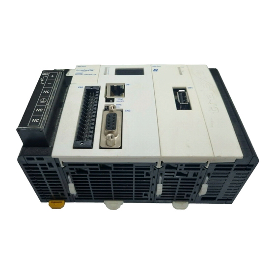
Page 64: Tj1-Mc
Hardware reference 3.3.4 PSU box contents • Safety sheet. • Power Supply Unit. • Protection label attached to the top surface of the unit. TJ1-MC__ 3.4.1 Introduction The TJ1-MC__ is the heart of the Trajexia system. You can program the TJ1-MC__ with the BASIC programming language to control the expansion units and the servo motors attached to the expansion units. - Page 65 Hardware reference 3.4.2 LED Display The LED display shows the following information: fig. 20 Information When IP address and sub- Shows 3 times when you connect the Trajexia system to the power net mask supply. IP address Shows 4 times when you connect an Ethernet cable to the Ethernet connector of the TJ1-MC__ and to a PC.
- Page 66 Hardware reference 3.4.3 TJ1-MC__ Connections The TJ1-MC__ comes with these connectors: fig. 21 • One Ethernet connector, to connect to a PC or Ethernet network (D) • One serial connector (G). • One 28-pin I/O connector (H). The parts for the serial connector and the 28-pin connector are supplied. Ethernet connector The Ethernet connector is used to connect the TJ1-MC__ to a PC or Ethernet network.
- Page 67 Hardware reference Serial connector The serial connector allows for three communication standards: fig. 22 • RS232. • RS422. • RS485. Communication Connection RS422/RS485 RS232 RS232 RS422/RS485 RS422/RS485 RS422/RS485 RS232 TERM ON/OFF Switch Sets the termination on/off of the RS422 / 485 serial connection. The setting of the TERM ON/OFF switch depends on the communication standard of the serial connection and the position of the TJ1-MC__ in the network: Communication...
- Page 68 Hardware reference WIRE 2/4 Switch The WIRE 2/4 switch sets the communication standard for the RS422/485 fig. 23 serial connection. To use one of the communication standards, do this: Communication standard How to select it RS422 Set the WIRE 2/4 switch right RS485 Set the WIRE 2/4 switch left Note...
- Page 69 Hardware reference 28-Pin I/O connector The 28 pin connector is a Weidmuller connector designation: B2L 3.5/28 LH. fig. 24 Connection Connection 0 V input common 0 V input common Input 0 Input 1 Input 2 Input 3 Input 4 Input 5 Input 6 Input 7 Input 8...
- Page 70 Hardware reference label IN 2 IN 10 IN 18 IN 26 OUT 2 OUT 10 OUT 18 OUT 26 IN 3 IN 11 IN 19 IN 27 OUT 3 OUT 11 OUT 19 OUT 27 IN 4 IN 12 IN 20 IN 28 OUT 4 OUT 12...
- Page 71 Hardware reference Digital outputs The following table and illustration details the digital output (O8 to O15) fig. 26 specifications: TJ 1-MC 16 Item Specification 2A Fuse 24V output supply Type External Maximum voltage 24 VDC + 10% power 19 O8 supply Equivalent Current capacity...
- Page 72 Hardware reference 3.4.4 Battery The backup battery provides power to the RAM, where programs and global fig. 27 variables are stored, and real Time Clock when the power supply is off. You must replace it every five years. The part number of the backup battery is CJ1W-BAT01.
- Page 73 Hardware reference Item Specification TJ1-MC04 TJ1-MC16 Servo period 0.5 ms, 1 ms or 2 ms Programming language BASIC-like motion language Multi-tasking Up to 14 tasks Digital I/O 16 digital inputs and 8 digital outputs, freely configurable Measurement units User-definable Available memory for user pro- 500 kB grams Data storage capacity...
- Page 74 Hardware reference Item Specification Transmission format, parity bit Even/odd/none Transmission mode • RS232C: Point-to-point (1:1) • RS422/485: Point-to-multipoint (1:N) Transmission protocol • Host link master protocol • Host link slave protocol • ASCII general purpose Galvanic isolation RS422/485 connector only Communication buffers 254 bytes Flow control...
-
Page 75: Tj1-Ml
Hardware reference 3.4.7 TJ1-MC__ box contents • Safety sheet. • TJ1-MC__ (battery included). • Protection label attached to the top surface of the TJ1-MC__. • TJ1-TER, attached to the TJ1-MC__. • Parts for a serial connector. • Parts for an I/O connector. •... - Page 76 Hardware reference 3.5.2 LEDs description Label Status Description Start-up test failed. Unit not operational Operation stopped. Fatal error Start-up test successful. Normal operation Normal operation A fault in the MECHATROLINK-II bus Reserved 3.5.3 TJ1-ML__ connection The MECHATROLINK-II bus connector (A) fits a MECHATROLINK-II fig.
- Page 77 Hardware reference Example connections Example 1 fig. 31 • 1 x TJ1-MC__ Servo Driver • 1 x TJ1-ML__ • 3 x Sigma-II Servo Driver • 1 x MECHATROLINK-II terminator Address Address Address Terminator Axis 2 Axis 3 Axis 4 HARDWARE REFERENCE MANUAL...
- Page 78 Hardware reference Example 2 fig. 32 • 1 x TJ1-MC16 Servo Drive • 2 x TJ1-ML16 • 16 x Sigma-II Servo Driver • 2 x MECHATROLINK-II terminator Address Address Address Address Address Address Address Address Terminator Axis 0 Axis 1 Axis 2 Axis 3 Axis 4...
- Page 79 Hardware reference The MECHATROLINK-II Units can control different combinations of axes, fig. 33 Inverters and I/O units. Example 3 • 1 x TJ1-MC__ • 1 x TJ1-ML16 • 1 x Sigma-II Servo Driver • 1 x Inverter • 3 x I/O units •...
- Page 80 FNY-W6003-10 Number of controlled devices 20 meters FNY-W6003-20 Controlled devices • Omron G-Series Servo Drivers 30 meters FNY-W6003-30 • Omron Accurax G5 Servo Drivers MECHATROLINK-II Terminating resistor FNY-W6022 • Sigma-II, Sigma-V and Junma-ML Servo Drivers terminator • I/Os MECHATROLINK-II For Sigma-II series Servo Drivers JUSP-NS115 •...
- Page 81 Hardware reference 3.5.7 MECHATROLINK-II Servo Drivers A MECHATROLINK-II Servo Driver is designed to do position control in Trajexia. In every MECHATROLINK-II cycle, the TJ1-MC__ receives the position feedback from the Servo Driver via the TJ1-ML__. The TJ1-MC__ sends either the target position, speed or torque to the receiver, depending on the axis type.
- Page 82 Hardware reference LED indicators on the NS115 fig. 35 Color Description Alarm Lit: an alarm occurred Not lit: no alarm active Ready Green Lit: communication active Not lit: no communication in progress Address settings (SW1 & SW2) The dipswitches (B) on the NS115 configure the communication settings. fig.
- Page 83 Hardware reference Set the address selector (A, fig 35) of the NS115 to n (where n ranges from 0 fig. 37 to F) to assign the following address to the NS115: Rotary Dipswitch 3 Station address Axis in motion controller switch number Do not use the addresses 40 and 51-5F.
- Page 84 Hardware reference MECHATROLINK-II connectors (CN1A & CN1B) Connect to the MECHATROLINK-II network as in the figure using a suitable fig. 38 MECHATROLINK-II cable. Both connectors are parallelled so you can connect both cables to both connectors. Connect a MECHATROLINK-II terminator resistor in one of the connectors if the Servo Driver is the last device in the network.
- Page 85 Hardware reference fig. 39 NS115 PG0V Signal ground PG0V Signal ground PG0V External PG 1,2,3 PG0V Signal ground External power supply Phase-C input + Phase-C input - Phase-A input + Phase-A input - Phase-B input + Phase-B input - Note Make sure that shielded cable is used and that the shield is con- nected to the connector shell.
- Page 86 Hardware reference Encoder gear ratio resolution These two parameters define the units of the system in combination with UNITS. • Pn202: Gear ratio numerator. Default is 4, set to 1 to obtain the maximum encoder resolution. • Pn203: Gear ratio denominator. Default=1. Absolute encoder •...
- Page 87 Hardware reference • DRIVE_ALARM • DRIVE_CLEAR • DRIVE_CONTROL • DRIVE_INPUTS • DRIVE_MONITOR • DRIVE_READ • DRIVE_RESET • DRIVE_STATUS • DRIVE_WRITE For more information, refer to the Trajexia Programming Manual. 3.5.9 MECHATROLINK-II Servo Drivers Sigma-V series You can also connect a Sigma-V Servo Driver to a Trajexia system. fig.
- Page 88 Hardware reference Label Terminal/LED Description Power LED Communication settings (SW2) The 4 dipswitches configure the communication settings. fig. 41 Dipswitch Function Setting Description Factory setting Baud rate 10 Mbps Data length 32-byte data transmission Address Addresses 40-4F range Addresses 50-5F Reserved Must always be set to off.
- Page 89 Hardware reference Address settings (SW1) Set the address selector of the Sigma-V Servo Driver to n (where n ranges fig. 42 from 0 to F) to assign the following station address to it: Rotary Dipswitch 3 Station address Axis in motion controller switch number Do not use the addresses 40 and 51-5F.
- Page 90 Hardware reference LEDs Color Description Charge indicator Orange Lit: main circuit power supply is on or internal capacitor is charged Not lit: no power supply and internal capacitor is not charged Power LED Green Lit: control power is supplied Not lit: no control power MECHATROLINK-II commu- Green Lit: communication active...
- Page 91 Hardware reference • Alarm/warning If an alarm or a warning occurs, the display shows the alarm code or the fig. 43 warning code. Status Unlit Unlit Unlit Unlit Unlit The figure shows an example of displaying alarm code A.E60. Display •...
- Page 92 Hardware reference Signal Signal name Signal Description PG serial signal input (-) Input /EXT3 External latch signal 3 Shell Shield Input /SIO General-purpose input signal Not used Related BASIC commands The following BASIC commands are related to the MECHATROLINK-II Not used Servo Drivers Sigma-V series: Output Signal ground...
- Page 93 Hardware reference 3.5.10 MECHATROLINK-II Servo Drivers Junma series You can also connect a Junma Servo Driver to a Trajexia system. fig. 45 Label Terminal/LED Description Rotary switch for reference filter setting COM ALM RDY CN6A & CN6B MECHATROLINK-II bus connectors I/O signal connector Encoder input connector Rotary switch for MECHATROLINK-II address settings...
- Page 94 Hardware reference Communication settings (SW2) The 4 dipswitches configure the communication settings. fig. 46 Dipswitch Function Setting Description Reserved Must always be set to ON. OFF is not used Data 32 bytes length Address Addresses 40-4F range Addresses 50-5F Filter Set the filter with the FIL rotary switch setting Set the filter with Pn00A...
- Page 95 Hardware reference Address settings (SW1) Set the address selector of the Junma Servo Driver to n (where n ranges fig. 47 from 0 to F) to assign the following station address to it: Rotary Dipswitch 3 Station address Axis in motion controller switch number Do not use the addresses 40 and 51-5F.
- Page 96 Hardware reference CN1 I/O Signal connector The table below shows the pin layout for the I/O signal connector (CN1). fig. 48 Code Signal name 8 9 10 11 12 13 14 Input /EXT1 External latch Input /DEC Homing deceleration Input N_OT Reverse run prohibit Input...
- Page 97 Hardware reference CN2 encoder input connector The tables below shows the pin layout for the Junma Servo Driver encoder fig. 49 connector. Signal PG5V 9 7 5 3 1 PG0V (GND) Phase A (+) Phase A (-) Phase B (+) Phase B (-) Phase /Z Phase U...
- Page 98 Hardware reference CNB servo motor connector The tables below shows the pin layout for the CNB servo motor connector. fig. 51 Signal Name Phase U Phase V Phase W Related BASIC commands The following BASIC commands are related to the MECHATROLINK-II Servo Drivers Junma series: •...
- Page 99 Hardware reference 3.5.11 MECHATROLINK-II Servo Drivers G-series You can also connect a G-Series Servo Driver to a Trajexia system. fig. 52 Label Terminal/LED Description SP, IM, G Analog monitor check pins L1, L2, L3 Main-circuit power terminals AC SERVO DRIVE L1C, L2C Control-circuit power terminals B1, B2, B3...
- Page 100 Hardware reference Address settings (SW1) Set the address selector of the G-series Servo Driver to the required node fig. 53 address by using the X1 (right) and X10 (left) rotary switches. Rotary switches for setting a node The setting range for the node address setting rotary switch is 1 to 31. The address actual station address used on the network will be the sum of the rotary 7-segment LED (2 digits)
- Page 101 Hardware reference 7-segment LED The display of the 7-segment LED on the front panel is shown below. fig. 54 Turn ON Control Power Supply When the power is turned ON, the node address set with the rotary switch is displayed, followed by the display content set by the Default Display (Pn001) All OFF parameter.
- Page 102 Hardware reference CN1 I/O Signal connector The table below shows the pin layout for the I/O signal connector (CN1). fig. 55 12 to 24-VDC Forward Drive +24VIN Power Supply Prohibit Input Code Signal name Input Emergency Reverse Drive STOP Stop Input Prohibit Input External Latch Input...
- Page 103 Hardware reference Code Signal name Output /ALM Alarm Output Output ALMCOM Output OUTM2 General-purpose Output 2 (READY) Output OUTM2COM Output OUTM3 General-purpose Output 3 (CLIM) Output OUTM3COM Output OUTM1 General-purpose Output 1 (BKIR) Output OUTM1COM Shell MECHATROLINK-II connectors (CN6A & CN6B) Connect the G-series Servo Driver to the MECHATROLINK-II network using fig.
- Page 104 Hardware reference CN2 encoder input connector The table below shows the pin layout for the encoder connector. Signal Name Encoder power supply +5 V Encoder power supply GND BAT+ Battery + BAT- Battery - Encoder +phase S input Encoder -phase S input Shell Shield ground CNA power supply connector...
- Page 105 Hardware reference CNB servo motor connector The table below shows the pin layout for the CNB servo motor connector. Signal Name External Regeneration Resistor connection terminals Servomotor connection terminals Frame ground HARDWARE REFERENCE MANUAL...
- Page 106 Hardware reference 3.5.12 MECHATROLINK-II Servo Drivers Accurax G5 You can also connect an Accurax G5 Servo Driver to a Trajexia system. fig. 57 Label Terminal/LED Description Display area Analog monitor check pins L1, L2, L3 Main-circuit power terminals L1C, L2C Control-circuit power terminals CHARGE Charge lamp...
- Page 107 Hardware reference MECHATROLINK-II Communications Status LED Indicator The table below shows the LED indication status and the corresponding conditions of the communications. LED status Communications status Not lit No communication is established. Green Flash Asynchronous communications is established. Green Light Synchronous communications is established.
- Page 108 Hardware reference Address settings (SW1) Set the address selector of the Accurax G5 Servo Driver to the required fig. 58 node address by using the X1 (right) and X10 (left) rotary switches. MECHATROLINK-II communications The setting range for the node address setting rotary switch is 1 to 31. The status LED indicator (COMM) actual station address used on the network will be the sum of the rotary Rotary switches for...
- Page 109 Hardware reference 7-segment LED The 7-segment LED indicator is on the front panel. fig. 59 When the power is turned on, it shows the node address that is set by the Turn ON Control Power Supply rotary switches. Then the indication changes in accordance with the setting on the Default Display (Pn700).
- Page 110 Hardware reference CN1 I/O Signal connector The table below shows the pin layout for the I/O signal connector (CN1). fig. 60 Absolute General-purpose encoder backup OUTM1 Output 1 Absolute Code Signal name battery input General-purpose encoder backup OUTM1COM BATGND Output 1 Common battery input Input +24 VIN...
- Page 111 Hardware reference MECHATROLINK-II connectors (CN6A & CN6B) Connect the G-series Servo Driver to the MECHATROLINK-II network using fig. 61 the CN6A and CN6B connectors. Use one of the MECHATROLINK-II MC Unit connectors to connect to the previous MECHATROLINK-II device or the TJ1-ML__.
- Page 112 Hardware reference CN2 Encoder input connector The table below shows the pin layout for the encoder connector. Signal Name Encoder power supply +5 V Encoder power supply GND BAT+ Battery + BAT- Battery - Encoder +phase S input Encoder -phase S input Shell Shield ground CN4 External encoder connector...
- Page 113 Hardware reference CN5 Monitor connector The table below shows the pin layout for the CN5 monitor connector. Signal Name Analog monitor output 1 Analog monitor output 2 Analog monitor ground Reserved: do not connect. Reserved: do not connect. Reserved: do not connect. CN7 USB Connector The table below shows the pin layout for the CN7 USB connector.
- Page 114 Hardware reference Signal Name Shell Shield ground CNA Power supply connector The table below shows the pin layout for the CNA power supply connector. Signal Name Main circuit power supply input Control circuit power supply input CNB Servo motor connector The table below shows the pin layout for the CNB servo motor connector.
- Page 115 Hardware reference • DRIVE_CLEAR • DRIVE_CONTROL • DRIVE_INPUTS • DRIVE_MONITOR • DRIVE_READ • DRIVE_RESET • DRIVE_STATUS • DRIVE_WRITE For more information, refer to the Trajexia Programming Manual. HARDWARE REFERENCE MANUAL...
- Page 116 Hardware reference 3.5.13 MECHATROLINK-II Inverter V7 A V7 Inverter with a MECHATROLINK-II interface is designed to make fig. 62 speed and torque control (if the Inverter supports this feature) of an AC induction motor. No position control is supported via MECHATROLINK-II. By default an Inverter is not considered an axis by the TJ1-MC__.
- Page 117 Hardware reference LED indicators The LED indicators indicate the status of the communications of the fig. 63 MECHATROLINK-II and the SI-T/V7 Unit. A. Run B. TX C. RX D. ERR Name Display Explanation Color Status Green Normal operation Not lit Communications CPU stopped, resetting hardware, RAM check error, DPRAM check error, station address setting error or Inverter model code error...
- Page 118 Hardware reference Dipswitch The following table shows the dipswitch settings of the SI-T/V7 Unit. fig. 64 Name Label Status Function Baud rate S1-1 10 Mbps (MECHATROLINK-II) Data length S1-2 32-byte data transmission (MECHATROLINK-II) Station S1-3 Set the 10th digit of the station number to 2. address Invalid if the maximum number of units including the S2 of the rotary switch is 20.
- Page 119 Hardware reference S1-3 Station number S1-3 Station number Fault To use the V7 Inverter with the MECHATROLINK-II interface it is necessary to make the following settings in the Inverter: • N3=3 Sequence via MECHATROLINK-II • N4=9 Reference via MECHATROLINK-II Check the manual for details about the V7 Inverter. Related BASIC commands The following BASIC commands are related to the MECHATROLINK-II Inverters V7 series:...
- Page 120 Hardware reference 3.5.14 MECHATROLINK-II Inverter F7 and G7 The F7 and G7 Inverters with a MECHATROLINK-II interface are designed fig. 66 to make speed and torque control (if the Inverter supports this feature) of an AC induction motor. No position control is supported via MECHATROLINK- By default an Inverter is not considered an axis by the TJ1-MC__.
- Page 121 Hardware reference The illustration shows the external appearance of the SI-T Card. fig. 67 A. LED B. Rotary switch C. Dipswitch D. Communications connector E. Code No. F. Type LED indicators The LED indicators indicate the status of the communications of the MECHATROLINK-II and the SI-T Card.
- Page 122 Hardware reference Name Display Explanation Color Status Watchdog timeout error, communication error, diagnosis error or resetting hardware Flashing ROM check error (once)*, RAM check error (twice)*, DPRAM check error (3 times)*, communications ASIC self-diagnosis error (4 times)*, ASIC RAM check error (5 times)*, station address setting error (6 times)*, Inverter model code error (7 times)* *: indicates the number of flashes...
- Page 123 Hardware reference Rotary switch The following table shows the rotary switch settings of the SI-T/V7 Unit. fig. 69 Label Status Function Factory set- ting 0 to F Set the 1st digit of the station number X0H-XFH. Invalid if the maximum number of units including the S1-3 is 20 or 3F.
- Page 124 Hardware reference To use the F7 or G7 Inverter with the MECHATROLINK-II interface it is necessary to make the following settings in the Inverter: • B1-01=3 Sequence via MECHATROLINK-II • B1-02=3 Reference via MECHATROLINK-II Check the corresponding manual for details about the F7 or G7 Inverter. Related BASIC commands The following BASIC commands are related to the MECHATROLINK-II Inverters F7 and G7 series:...
- Page 125 Hardware reference D. Output signal connector 2 E. Power supply terminals F. I/O indicator switch G. Station number switch H. Dipswitch for setting MECHATROLINK-II connector J. I/O indicators Connector description I/O and Status Indicators: fig. 71 R Active F Indicator Indicator Color Meaning when lit Name...
- Page 126 Hardware reference I/O Signal connector: Connect the I/O Unit with external I/O signals through the I/O Cable. fig. 74 Number of I/O points: 64 inputs and 64 outputs IN 1 OUT 1 IN 2 OUT 2 B1 A1 B1 A1 B1 A1 HARDWARE REFERENCE MANUAL...
- Page 127 Hardware reference Digital I/O layout The pin layout of the I/O connectors is the same for the IO2310, and IO2330 modules. The following table shows the pin layout of the IN1 connector. Signal name Remarks Signal name Remarks (NC) (NC) +24V_2 24-V power sup- +24V_2...
- Page 128 Hardware reference The following table shows the pin layout of the IN2 connector. Signal name Remarks Signal name Remarks (NC) (NC) +24V_4 24-V power +24V_4 24-V power sup- supply 4 ply 4 IN64 Input 64 IN63 Input 63 IN62 Input 62 IN61 Input 61 IN60...
- Page 129 Hardware reference The following table shows the pin layout of the OUT1 connector. Signal name Remarks Signal name Remarks 024V_6 Common 024V_6 Common ground ground 6 +24V_6 24-V power +24V_6 24-V power sup- supply 6 ply 6 OUT32 Output 32 OUT31 Output 31 OUT30...
- Page 130 Hardware reference The following table shows the pin layout of the OUT2 connector. Signal name Remarks Signal name Remarks 024V_8 Common 024V_8 Common ground ground 8 +24V_8 24-V power +24V_8 24-V power sup- supply 8 ply 8 OUT64 Output 64 OUT63 Output 63 OUT62...
- Page 131 Hardware reference I/O Cable: fig. 75 The following table shows the standard I/O cable models. The standard cable is used for both IO2310 and IO2330 modules. Name Model Length (m) I/O Cable JEPMC-W5410-05 JEPMC-W5410-10 JEPMC-W5410-30 Station number and dipswitch settings Station Number switch sets the station number of the module in the fig.
- Page 132 Hardware reference Station Dipswitch 3 Station Station Dipswitch 3 Station Address number Address number switch switch 1(61h) 16(70h) 2(62h) 17(71h) 3(63h) 18(72h) 4(64h) 19(73h) 5(65h) 20(74h) 6(66h) 21(75h) 7(67h) 22(76h) 8(68h) 23(77h) 9(69h) 24(78h) 10(6Ah) 25(79h) 11(6Bh) 26(7Ah) 12(6Ch) 27(7Bh) 13(6Dh) 28(7Ch) 14(6Eh)
- Page 133 Hardware reference Power supply input The external wiring terminal supplies 24 VDC to the I/O module. fig. 78 Terminal name Function DC24V +24 VDC 24 VDC DC0V 0 VDC Protective ground terminal 0 VDC Specification Input circuit: fig. 79 The input circuit specifications are shown below. The input circuit is used + 5V both for IO2310, and IO2330 modules.
- Page 134 Hardware reference Output circuit: fig. 80 The output specifications are shown below. + 24V + 24V Item Specifications Module IO2310 IO2330 Number of output points 64 points (32 point x 2) 10 kΩ Output type Transistor, open collector or Transistor, open collector or O24V sinking sourcing...
- Page 135 Hardware reference Related BASIC commands The following BASIC commands are related to the MECHATROLINK-II digital I/O module: • • • For more information, refer to the Trajexia Programming Manual. HARDWARE REFERENCE MANUAL...
- Page 136 Hardware reference 3.5.16 MECHATROLINK-II 4-Channel analogue input module This is a 4-channel analogue input MECHATROLINK-II slave. The analogue fig. 81 inputs are automatically allocated by the Trajexia system according to the unit number and can be read by Trajexia starting from AIN(0). The I/Os are automatically mapped in AIN(x) according to the MECHATROLINK-II node number.
- Page 137 Hardware reference Indicator Indicator color Meaning when lit or flashing name A communication error occurred Offset/gain setting error Flashing Self-diagnostic error CH1 to CH4 Green Each LED indicates that the input is out-of-range for that channel. Out-of-range inputs are as follows: +10.02 V <...
- Page 138 Hardware reference Pin No. Slave address Not used HARDWARE REFERENCE MANUAL...
- Page 139 Hardware reference Pin No. Slave address Not used Specification The performance specifications of the analogue input module (±10 V, 4 CH) are shown below. Item Specifications Name Analog input module (-10 V to + 10 V, 4 CH) Model description AN2900 Model number JEPMC-AN2900...
- Page 140 Hardware reference Item Specifications Input filter characteristics Software filter Number of allocated words 5 words/module Maintenance/diagnostic functions Watchdog timer External connections Removable terminal block with 23 M3 screw terminals fig. 84 Item Specifications Input circuit iso- Isolation Photocoupler lation method (There is no isolation between input channels.) Dielectric 1,500 VAC for 1 minute between input terminals and...
- Page 141 Hardware reference 3.5.17 MECHATROLINK-II 2-Channel analogue output module This is a 2-channel analogue output MECHATROLINK-II slave. The fig. 85 analogue output is automatically allocated by the Trajexia system according to the unit number and can be read by Trajexia starting from AOUT(0). The I/Os are automatically mapped in AOUT(x) according to the MECHATROLINK-II node number.
- Page 142 Hardware reference Indicator Indicator color Meaning when lit or flashing name Green Receiving data A communication error occurred Offset/gain setting error Flashing Self-diagnostic error Dipswitch functions: fig. 87 The dipswitch consists of eight pins. The pins are numbered 1 to 8, as shown in the following diagram.
- Page 143 Hardware reference Pin No. Slave address Not used HARDWARE REFERENCE MANUAL...
- Page 144 Hardware reference Pin No. Slave address Not used Specification The performance specifications of the analogue output module (±10 V, 2 CH) are shown below. The illustration shows the circuit configuration for the analogue input module. fig. 88 Item Specifications Name Analog output module (-10 V to +10 V, 2 CH) +12V Status...
- Page 145 Hardware reference Item Specifications Output status when master stops Mode selected with the dipswitch (SW7): SW7 off: clear outputs (output 0 V) SW7 on: retain prior output status External connections Removable terminal block with M3 screw terminals Output circuit Isolation method Photocoupler isolation (There is no isolation between channels.) Dielectric...
- Page 146 Hardware reference fig. 89 Terminal/LED Label Description CN1 communication indicator CN2 communication indicator POWER Power indicator Dipswitch CN1 & CN2 MECHATROLINK-II connectors Power supply connector LED indicators Description POWER Lit: Power on Not lit: No power Lit: Communication via CN1 Not lit: No communication via CN1 Lit: Communication via CN2 Not lit: No communication via CN2...
- Page 147 Hardware reference The table below gives the pin layout for the power supply connector. fig. 90 Signal Description Frame ground 0 VDC input +24 V 24 VDC input Dipswitch settings (SW) The dipswitch is for future use. Set all the pins to OFF. System configuration The maximum number of MECHATROLINK-II devices that you can connect fig.
-
Page 148: Grt1-Ml2
MECHATROLINK-II network. For more information on SmartSlice I/O Units, refer to the GRT1 Series SmartSlice I/O Units Operation Manual (W455). fig. 92 Label Description LED indicators GRT1-ML2 OMRON UNIT PWR ALARM Unit dipswitches ML COM I/O PWR Unit power supply terminals... - Page 149 Hardware reference Dipswitch Function Setting Description Automatic OFF to ON When the SmartSlice I/O Units are restore replaced, the parameter data that was backed up with the BACK dipswitch is automatically restored Automatic restore disabled BACK Backup trigger ON to OFF to Parameter data of all connected Smart- ON in 3 s Slice I/O Units is backed up...
- Page 150 Hardware reference LED indicators fig. 95 Description Color Status Meaning Unit status Green Not lit • Startup test failed, unit not opera- tional UNIT PWR • Operation stopped due to a fatal ALARM error ML COM I/O PWR Initialization successful, unit is in nor- mal operation ALARM Unit error...
- Page 151 Hardware reference Description Color Status Meaning Note SmartSlice I/O Not Lit • No power supply system com- • Communication with SmartSlice I/ • When the power of the Trajexia system is turned on, the TJ1- munication O Unit has not started MC__ executes its startup sequence before it initializes the status •...
- Page 152 Hardware reference Rotary switch The rotary switch (SW1) sets the MECHATROLINK-II address that identifies the GRT1-ML2 in the MECHATROLINK-II network. The settings range is from 0 hex to F hex. To set the MECHATROLINK-II address of the GRT1-ML2, do these steps: 1.
- Page 153 Hardware reference Dipswitch 1 Rotary Address Dipswitch 1 Rotary Address switch switch 6F hex Note Make sure that the address is unique in the MECHATROLINK-II network. If two or more units have the same MECHATROLINK-II address, they cannot be initialized properly. 3.
- Page 154 Hardware reference 3.6.2 Specifications Item Specification Unit type SmartSlice GRT1 series Model GRT1-ML2 Installation position On a DIN rail 24 VDC +10% −15% (20.4 to 26.4 VDC) Power supply Current consumption 110 mA typical at 24 VDC Dimensions (W × H × D) 58 × 80 × 70 mm Weight 130 g −10 to 55°C (no icing or condensation)
- Page 155 Hardware reference Item Specification Number of connectable 64 Units max. SmartSlice I/O Units Connected directly to the GRT1-ML2 or via Turnback exten- sion units Baud rate 3 Mbps Communication signal RS485 level Communication dis- SmartSlice I/O Units: 64 Units coupled (about 2 m max.) tance Turnback cable: 2 m max.
- Page 156 Hardware reference Function Specification Model 4 PNP outputs 24 VDC, 500 mA, 2-wire connection GRT1-OD4-1 4 PNP outputs with short- 24 VDC, 500 mA, 3-wire connection GRT1-OD4G-1 circuit protection 8 NPN outputs 24 VDC, 500 mA, 1-wire connection + GRT1-OD8 8 PNP outputs 24 VDC, 500 mA, 1-wire connection + GRT1-OD8-1...
- Page 157 Hardware reference Dimensions The external dimensions are in mm. fig. 97 GRT1-ML2 OMRON UNIT PWR ALARM ML COM I/O PWR REGS BACK UNIT UNIT -V -V -V -V DC24V DC24V INPUT INPUT 26.3 28.8 17.1 61.2 36.8 69.7 3.6.3 Installation Follow these rules when installing the GRT1-ML2: •...
- Page 158 Hardware reference • Provide separate conduits or ducts for the I/O lines to prevent noise from high-tension lines or power lines. • It is possible to connect up to 64 SmartSlice I/O Units to 1 GRT1-ML2. • Install the GRT1-ML2 and the SmartSlice I/O Units on a DIN rail. To install a GRT1-ML2 on the DIN rail, press it onto the DIN track from the front, and press the unit firmly until it clicks.
- Page 159 Hardware reference 1. Calculate the power consumption of all SmartSlice I/O Units connected to the GRT1-ML2. Refer to the GRT1 Series SmartSlice I/O Units Operation Manual (W455) for the power value for each SmartSlice I/O Unit. 2. If the power consumption exceeds 80 W, mount a Right Turnback Unit (GRT1-TBR) on the SmartSlice I/O Unit at the point where the power consumption is less than 80 W.
- Page 160 I/O, an output voltage of 30 V rms and a 42.4 V peak or maximum of 60 VDC. Recommended power supplies are: • S82K-01524 (OMRON) • S8TS-06024 (OMRON). Releas e button It is recommended to use wires with a gauge of 20 AWG to 16 AWG (0.5 to 1.25 mm...
- Page 161 Remove any lint or threads left from the cloth. Install the unit again. • When returning a damaged unit to the OMRON dealer, include a detailed damage report with the unit. • Before reconnecting the new unit, do these steps: Set the MECHATROLINK-II station address to the same address as the old unit.
- Page 162 Hardware reference 3. Remove the main block of the unit. Replace it with a new SmartSlice I/O Unit of the same type. 4. Attach the new unit to the system. Close the locks on the front of the unit. 5. Turn on the power supplies to the unit. When replacing a SmartSlice I/O Unit online, note the following things: •...
-
Page 163: Tj1-Prt
Hardware reference TJ1-PRT 3.7.1 Introduction The TJ1-PRT is an interface between the Trajexia system and a PROFIBUS fig. 101 network. The TJ1-PRT has these visible parts. Part Description LEDs B and C Node number selectors PROFIBUS connector 3.7.2 LEDs description Label Status Description... - Page 164 Hardware reference Label Status Description No PROFIBUS data exchange communication I/O data exchange on PROFIBUS is active No PROFIBUS bus communication errors flashing Parameter values sent by the PROFIBUS master unit are invalid. I/O data exchange is not possible. No PROFIBUS communication is detected by the unit 3.7.3 Node number selectors You can use the node number selectors to assign a node number to the TJ1-...
- Page 165 Hardware reference 3.7.4 TJ1-PRT Connections fig. 102 Signal Description Shield Connected to the metal shell B-line Data signal Direction control signal for repeaters DGND Data 0 Volts Power output for the termination, 5 V, 10 mA A-line Data signal 3.7.5 TJ1-PRT Specifications Item Specification...
- Page 166 Hardware reference 3.7.6 TJ1-PRT unit box contents TJ1-PRT box: • Safety sheet. • TJ1-PRT. • Protection label attached to the top surface of the unit. 3.7.7 Applicable BASIC commands The following BASIC commands are applicable for the TJ1-PRT: • PROFIBUS For more information, refer to the Trajexia Programming Manual.
-
Page 167: Tj1-Drt
Hardware reference TJ1-DRT 3.8.1 Introduction The TJ1-DRT is an interface between the Trajexia system and a DeviceNet fig. 103 network. Part Description LEDs B and C Node number selectors DeviceNet connector 3.8.2 LEDs description CAN L DRAIN Label Status Description CAN H Start-up test failed. - Page 168 Hardware reference Label Status Description No network error detected. flashing Connection time-out detected for I/O connection with the Device- Net master. Other device detected with the same node number or severe net- work error detected. 3.8.3 Node number selectors You can use the node number selectors to assign a node number to the TJ1- DRT.
- Page 169 Hardware reference 3.8.4 TJ1-DRT Connections fig. 104 Signal Description Power supply input, negative voltage CAN L Communication line, low DRAIN Shield CAN H Communication line, high Power supply input, positive voltage 3.8.5 TJ1-DRT Specifications Item Specification Power supply 5 VDC (supplied by the TJ1-MC__) Power consumption 120 mA at 5 VDC Network power supply...
- Page 170 Hardware reference Item Specification Node numbers 0 to 63 I/O size 0 to 32 words (16-bit), configurable, for both directions Galvanic isolation 3.8.6 TJ1-DRT unit box contents TJ1-DRT box: • Safety sheet. • TJ1-DRT. • DeviceNet connector. • Protection label attached to the top surface of the unit. 3.8.7 Applicable BASIC commands The following BASIC commands are applicable for the TJ1-DRT:...
-
Page 171: Tj1-Cort
Hardware reference TJ1-CORT 3.9.1 Introduction The CANopen Master Unit (TJ1-CORT) is an interface between the Trajexia system and a CANopen network. fig. 105 Part Description CORT LED indicators NWST B and C Node number selectors CANopen port CAN L DRAIN CAN H 3.9.2 LEDs description... - Page 172 Hardware reference Label Status Description Normal operation. flashing I/O size not configured. Error detected in communication with controller. NWST Start-up error or fatal error detected. single flash TJ1-CORT in stopped state. flashing TJ1-CORT in pre-operational state. TJ1-CORT in operational state. No network error detected.
- Page 173 Hardware reference 3.9.4 TJ1-CORT connections fig. 106 Signal Description Power supply input, negative voltage CAN L Communication line, low DRAIN Shield CAN H Communication line, high Power supply input, positive voltage 3.9.5 TJ1-CORT specifications Item Specification Power supply 5 VDC (supplied by the TJ1-MC__) Power consumption 120 mA at 5 VDC Network power supply...
- Page 174 Hardware reference Item Specification Communication ports 1 CAN port Transmission speed 20, 50, 125 and 500 Kbps Node numbers 1 to 99 I/O size 8 RPDO and 8 TPDO Galvanic isolation Device profile DS302: CANopen manager profile Note: This CANopen master does not support motion control features of slaves with the DS401 profile 3.9.6 TJ1-CORT unit box contents...
-
Page 175: Tj1-Fl02
Hardware reference 3.10 TJ1-FL02 3.10.1 Introduction WARNING Do not start the system until you check that the axes are present and of the correct type. The numbers of the Flexible axes will change if MECHATROLINK- II network errors occur during start-up or if the MECHATROLINK-II network configuration changes. - Page 176 Hardware reference Axis Label Status AXIS_DISPLAY parameter The TJ1-MC__ recognises the TJ1-FL02 A EN Axis enabled. flashing Axis error Axis disabled REG 0 OUT 0 Encoder A REG 1 Encoder Z OUT 1 Encoder B B EN Axis enabled flashing Axis error Axis disabled REG 0...
- Page 177 Hardware reference 15-pin connector fig. 108 Axis Encoder Encoder Stepper SSI/EnDat Tamagawa input output output Step+ Clock+ Step- Clock- Dir+ Dir- Enable+ Data+ Enable- Data- Enable+ Enable+ Data+ Enable- Enable- Data- +5V out Do not use Do not use Do not use Do not use Step+ Clock+ Step-...
- Page 178 Hardware reference 18-pin connector fig. 109 Axis Signal Axis Signal Description Vout Vout Analog output 0V Reference for Vout Wdog- Wdog+ Enable relay contacts Reg 0 Reg 0 24V registration inputs Reg 1 Reg 1 24V registration inputs 24V auxiliary inputs OUT 0 OUT 0 position switch outputs...
- Page 179 Hardware reference Note In the case of an incorrect registration due to slow edges or noise, a digital noise filter can be enabled with the REGIST command. Refer to the BASIC Commands in the Programming Manual. Note A maximum of 4 inputs on is allowed simultaneously. Digital outputs The following table and illustration details the digital output specifications: fig.
- Page 180 Hardware reference Analog outputs The following table and illustration details the analog output specifications: fig. 112 Item Specification TJ1-FL02 Output voltage -10 to +10 V +15V Vout 0 Resolution 16 bit -15V 100 Ω Output impedance Isolated 0V 10 k Ω min Load impedance Note The analogue output of one flexible axis is always 0V unless both...
- Page 181 Hardware reference Encoder interface The following table and illustration details the encoder interface: fig. 114 Item Specification TJ1-FL02 A0+ / Type Phase differential incremental encoder STEP0+ / Signal level EIA RS-422-A Standards (line-driver) A0- / STEP0- / Input impedance 48 kΩ min 220 Ω...
- Page 182 Hardware reference TJ1-FL02 F7 Inverter Signal Description pin number Wdog+ Enable relay contacts The cable for pins 1 and 3 must be shielded twisted pair. The cables for pins 5 and 6 are two single strand cables. Make the connections for the 15 pin connector on the TJ1-FL02 to the PG- X2 option board on the F7 Inverter as follows: TJ1-FL02 F7 Inverter...
- Page 183 Hardware reference Item Specification Number of axes Control method • +/- 10 V analogue output in Closed Loop • Pulse Train output in Open Loop Encoder position/speed feedback Incremental and absolute Absolute encoder standards sup- • SSI 200 kHz ported •...
- Page 184 When you use an encoder from other manufacturers, check the encoder specification for the phase advancement carefully. If the phase definition is different from the phase definition of the standard OMRON equipment, reverse the B-phase wiring between the TJ1-MC__ and the encoder.
- Page 185 Hardware reference The table below and the figure give an example of how to connect the fig. 117 OMRON E6B2-CWZ1Z encoder to the TJ1-FL02. TJ1-FL02 Encoder TJ1-FL02 Signal Wire color Signal Black Black/red White 0 V (COM) White/red 5 VDC...
- Page 186 Hardware reference 3.10.7 Absolute encoder SSI (Synchronous Serial Interface) is a digital system for transferring data in serial form. SSI is the most widely used serial interface between absolute sensors and controllers. SSI uses a pulse train from the controller to clock out the data from the sensor.
- Page 187 Hardware reference Encoder signal Axis A Axis B DATA+ DATA- CLOCK+ CLOCK- 5 / 15 5 / 15 Note The TJ1-FL02 does not have a termination inside. In case of long distances or disturbed communication, add an external termina- tion to the TJ1-FL02. The table below and the figure give an example of how to connect the fig.
- Page 188 Hardware reference EnDat the controller. When you set the encoder to the relevant encoder You can configure the TJ1-FL02 to mode, the axis transmits an interface directly to EnDat absolute information request to the encoder encoders. EnDat absolute encoders on a fixed 250 µs cycle. respond on a dedicated Clock and The connections for EnDat are: Data 1 MHz RS485 serial interface...
- Page 189 Hardware reference Encoder TJ1-FL02 Signal Wire color Signal White See footnote Blue 1. Use an external power supply Related BASIC commands The TJ1-FL02 can interface directly The following BASIC commands are to Tamagawa “SmartAbs” absolute related to EnDat absolute encoders: encoders.
- Page 190 Hardware reference The table below and the figure give an example of how to connect the fig. 123 Tamagawa TS5667N420 encoder to the TJ1-FL02. TJ1-FL02 Encoder TJ1-FL02 Signal Wire color Signal Blue Blue/Black Black Use an external power supply 5 VDC Power Supply Related BASIC commands The following BASIC commands are related to Tamagawa absolute encoders:...
- Page 191 Hardware reference 3.10.8 Stepper The TJ1-FL02 can generate pulses to drive an external stepper motor fig. 124 amplifier. You can use single step, half step and micro-stepping drivers with this interface. Applicable signals: • Enable ENABLE • Step • Direction. STEP Related BASIC commands The following BASIC commands are related to stepper outputs:...
- Page 192 Hardware reference 3.10.10 Hardware PSWITCH The TJ1-FL02 has 2 outputs that you can use as hardware position switches. These outputs go on when the measured position of the predefined axis is reached. They go off when another measured position is reached.
-
Page 193: A Differences Between Sigma-Ii And Junma
Differences between Sigma-II and Junma Differences between Sigma-II and Junma • Sigma-II can work in all three control modes: position mode (ATYPE=40), speed mode (ATYPE=41) and torque (force) mode (ATYPE=42). These are the differences between Sigma-II and Junma Servo Drivers and •... -
Page 194: Revision History
Revision history Revision history A manual revision code shows as a suffix to the catalogue number on the front cover of the manual. Revision code Date Revised content August 2006 Original October 2006 DeviceNet update May 2007 Updated with TJ1-MC04, TJ1-ML04, JUNMA series Servo Drivers and the MECHATROLINK-II repeater. Updated with motion control concepts, servo system principles and detailed encoder information. - Page 195 Apodaca, N.L. • 52.811.156.99.10 • 001.800.556.6766 • mela@omron.com 54.11.4783.5300 OMRON EUROpE B.V. Wegalaan 67-69, NL-2132 JD, Hoofddorp, The Netherlands. Tel: +31 (0) 23 568 13 00 Fax: +31 (0) 23 568 13 88 www.industrial.omron.eu Note: Specifications are subject to change.